• 검색 결과가 없습니다.

Implementation of Effective Wireless Power Transmission Circuit for Low Power System

N/A
N/A
Protected

Academic year: 2021

Share "Implementation of Effective Wireless Power Transmission Circuit for Low Power System"

Copied!
4
0
0

로드 중.... (전체 텍스트 보기)

전체 글

(1)

Ⅰ. Introduction

Wireless power transfer (WPT) [1] is a technology that can be used for transmitting the power to an electrical device without the use of wires. There are two kinds of inductive coupling and magnetic resonant coupling methods. In 1899, Nikola Tesla started to study a wireless transfer device. In 1946, William C. Brown invented wireless power transmission by using a rectenna, a rectifying antenna, converting microwave energy into direct current electricity.

Compared with the induction coupling method [2], Magnetic resonance, which uses the principle of strong magnetic coupling, has a long transmission distance.

Ⅱ. Design of Wireless Power Transfer Circuit

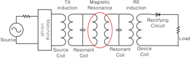
The equivalent magnetic resonant coupling circuit is shown in Fig. 1. Compared with the original inductive circuit [3], the magnetic resonant coil is added to the circuit.

Source

TX induction

Source Coil

Resonant Coil

Device Coil RX induction

Rectifying Circuit

Load Resonant

Coil Magnetic Resonance

Fig. 1. A scheme for wireless power transmission using resonant coil.

The simulation circuit using LT SPICE for transmitting/receiving part of the magnetic

Implementation of Effective Wireless Power Transmission Circuit for Low Power System

Young Hwan Lho

*

Abstract

Wireless power transfer (WPT) is the technology that enables the power to transmit electromagnetic field to an electrical load without the use of wires. There are two kinds of magnetic resonant coupling and inductive coupling ways transmitting from the source to the output load. Compared with microwave method for energy transfer over a long distance, the magnetic resonance method has the advantages of reducing the barrier of electromagnetic wave and enhancing the efficiency of power transmission. In this paper, the wireless power transfer circuit having a resonant frequency of 13.45 MHz for the low power system is studied, and the hardware implementation is accomplished to measure the power transmission efficiency for the distance between the transmitter and the receiver.

Key words:wireless power transfer, wireless resonant frequency, power efficiency, magnetic resonance, coupling coefficient

* Dept. of Railroad Electrical System Engineering, Woosong University

★ Corresponding author

E-mail:[email protected], Tel:+82-42-629-6731

※ Acknowledgment

This research is based on the support of 2018 Woosong University Academic Research Funding Manuscript received Jul. 25, 2018; revised Sep. 20, 2018; accepted Sept. 20, 2018

This is an Open-Access article distributed under the terms of the Creative Commons Attribution Non-Commercial License (http://creativecommons.org/licenses/by-nc/3.0) which permits unrestricted non-commercial use, distribution, and reproduction in any medium, provided the original work is properly cited.

ISSN:1226-7244 (Print)

ISSN:2288-243X (Online) j.inst.Korean.electr.electron.eng.Vol.22,No.3,846∼849,September 2018

논문번호 18-03-50 http://dx.doi.org/10.7471/ikeee.2018.22.3.846

325

(846)

(2)

326 j.inst.Korean.electr.electron.eng.Vol.22,No.3,846∼849,September 2018

induction method is shown in Fig. 2. The source frequency ranges from 1 Mhz to 20 Mhz. The coupling coefficient [3] of kxy is ranged from 0 to 1.

Fig. 2. The transmitting/receiving part of the magnetic induction circuit.

The power transmission efficiency of S

21

is defined by eq. (1).

(1)

where VL indicates the load voltage, VS the source voltage, RS the source resistance, and RL the load resistance.

The magnitude of S

21

is affected by the frequency and the coupling coefficient of k

23

depending on the distance between the sending and receiving coils. The mutual inductance increases as the distance decreases and vice versa. The increased distance enables the transmission efficiency to be reduced and result in mismatching two coils. As shown in Fig. 3, the magnitude of transmission efficiency increases as the coupling coefficient increases, having the centered resonant frequency of 13.45 Mhz.

In order to obtain the corresponding inductance for transmitting/ receiving coils of the magnetic induction method, the structure of coils is shown in Fig. 4. The turns of transmitting and receiving coils are 10 and 5.

The mutual inductance is obtained from the distance ranging 2 mm to 10 mm. The maximum inductance of transmitter is 886 nH and the one of receiver is 135.7 nH, and then the mutual inductance is 122.996 nH. The minimum mutual

inductance is obtained for the distance of 10 mm.

As shown in Fig. 5, the mutual inductance decreases as the mutual distance between transmitter and receiver increases.

Fig. 5. The inductances vs. distance.

Fig. 3. The magnitude and phase of S21 vs. k (coupling coefficient).

Fig. 4. The structure of transmitter and receiver for the inductive method.

(847)

(3)

Implementation of Effective Wireless Power Transmission Circuit for Low Power System 327

Ⅲ. Simulation and Implementation

The simulation circuit shown in Fig. 6 is to represent the relationship between the degree of coupling coefficient and the shape of frequency.

The frequency is split from the coupling coefficient of greater than 0.01. At the centered frequency of 13.45 Mhz, the resonant phenomenon occurs for less than 0.01 as shown in Fig. 7.

Fig. 6. The simulation circuit for magnetic resonant method.

As shown in Fig. 8, the enamel copper wire is wounded 6 turns with diameter of 37~46 mm for the inductance of 2.8 µH and 3 turns for the inductance of 17.5 µH. The corresponding capacitance of 50 pF and 8 pF are set to make the resonant frequency of 13.45 Mhz.

Fig. 7. Power transmission efficiency of S21.

The power transmission efficiency [4]using the S-parameters is represented by eq. (2).

(2)

Fig. 8. 6 turns and 3 turns with the diameter of 37~

46mm.

Fig. 9. S-parameter measurement circuit for transmission distance.

The power transmission efficiency shows the maximum value of 93.3% at the mutual distance of 10 mm, while the split occurs at the short distance of 5 mm. As the distance increases, the efficiency measured in Fig. 9 decreases as shown in Fig. 10.

Fig. 10. Efficiency by magnetic resonant way vs.

transmission distance.

(848)

(4)

328 j.inst.Korean.electr.electron.eng.Vol.22,No.3,846∼849,September 2018

Ⅳ. Conclusions

The WPT circuit is successfully designed, and the relationship between the coupling coefficient and the power transmission efficiency is analyzed.

It is proved that the power transmission efficiency using magnetic resonant method decreases as the transmission distance increases except the distance that the split frequency occurs. The hardware implementation for applying WPT system in real time is accomplished for analyzing the power transmission efficiency.

References

[1] Homepage of Wireless Power Consortium, http://www.wirelesspowerconsortium.com.

[2] Junfeng Chen et al, “Metamaterial- Based High-Efficiency Wireless Power Transfer System at 13.56 MHz for Low Power Applications,”

Progress In Electromagnetics Research B, Vol.

72, 17-30, 2017. DOI:10.2528/PIERB16071509 [3] Hoang Minh Huy, “Efficiency Improvement of Wireless Power Transfer by using of Adaptive Circuit,” Journal of The Institute of Electronics Engineers of Korea, Vol.38, NO.10, Oct.2011 (in Korean).

[4] Donggeon Kim and Chulhun Seo, “Omnidirectional Resonator in X-Y Plane Using a Crisscross Structure for Wireless Power Transfer,” Journal of Electromagnetic Engineering and Science, Vol.

15, No.3, 194-198, 2015.

(849)

수치

Fig.  1.  A  scheme  for  wireless  power  transmission  using  resonant  coil.
Fig.  4.  The  structure  of  transmitter  and  receiver  for  the  inductive  method.
Fig.  8.  6  turns  and  3  turns  with  the  diameter  of  37~

참조

관련 문서

∙ Always turn off the power supply and unplug the power cord from the power outlet before installing or removing any computer component.. ∙ Keep this user guide

The paper examines the incentives of power generating companies (GENCOs) for efficient fuel procurement for power generation under the Cost-Based Generation

 Units of the average power are watts, while units of complex power are volt-amps(VA), and the units of reactive power are volt-amp reactive (VAR)... Complex Power in

A Study on the Wireless Power Transmission of magnetic resonance using Superconducting

Sufficient Electricity and Fresh Water for a City of 100,000 Population Appropriate for Small Grid Size or Localized

In compact rectenna design, wireless power transmission technology is expected to be low power and low voltage in order to drive wireless

In this paper, we propose tree-based greedy algorithm to solve the minimum power broadcasting problem for minimizing the total transmit power on broadcasting in wireless

23 23 23 Standard 23 Standard Standard deviation, Standard deviation, deviation, mean deviation, mean mean mean for for for for the the the the power power