I.INTRODUCTION
Modern and future warfare is shifting toward a space envi-ronment with manned and unmanned weapons. The need for unmanned aerial vehicles (UAVs) is increasing. The modern military weapons system is based on the use of communication, sensors, and navigation equipment to accomplish a given task, even in hard-to-reach areas [1]. UAVs include all types of equipment, including drones, satellites, and missiles, among others. However, as UAVs become more advanced, their maintenance and repair also require a higher level of scientific
technology. Conventional UAVs depend on fuel cells with high-energy density for operations. The fuel cell will not stop burning once it has been ignited [2]. UAVs with fuel cells have a 10-year life span. They can avoid misfire and accidents by conducting periodic safety maintenance of the charging and power supply systems. The current UAV power supply nance method is shown in Fig. 1 [3]. However, this mainte-nance method has three problems. First, a large number of di-rect cables must be connected and then disassembled each time to supply the power. This condition increases the possibility that maintenance time is expanded or that maintenance efficiency is
Abstract
Unmanned aerial vehicles (UAVs) using communications, sensors, and navigation equipment will play a key role in future warfare. Cur-rently, UAVs are monitored to prevent misfire and accidents, and the conventional method adopted uses wires for data transmission and power supply. The repeated connection and disconnection of cables increases maintenance time and harms the connector. For conven-ience and stability, a wireless power transfer system to power UAVs is needed. Unlike other wireless power transfer (WPT) applications, the size of the receiving coils must be small, so that the WPT systems can be embedded inside space-limited UAVs. The small size re-duces the coupling coefficient and transfer efficiency between the transmitting and the receiving coils. In this study, we propose a toroi-dal-shaped coil for a WPT system for UAVs with high coupling coefficient with minimum space requirements. For validation, conven-tional coils and the proposed toroidal-shaped coil were used and their coupling coefficient and power transfer efficiency were compared using simulated and measured results. The simulated and measured results were strongly correlated, confirming that the proposed WPT system significantly improved efficiency with negligible change in the space requirement.
Key Words: Coupling Coefficient, Power Transfer Efficiency, Unmanned Aerial Vehicles, Wireless Charging, Wireless Power Transfer.
Manuscript received May 2, 2018 ; Revised July 23, 2018 ; Accepted October 30, 2018. (ID No. 20180502-039J)
1The Cho Chun Shik Graduate School of Green Transportation, Korea Advanced Institute of Science and Technology (KAIST), Daejeon, Korea. 2EMC Doctors Inc., Hwaseong, Korea.
3WISTEK Co. Ltd., Gunpo, Korea. *
Corresponding Author: Seungyoung Ahn (e-mail: [email protected])
This is an Open-Access article distributed under the terms of the Creative Commons Attribution Non-Commercial License (http://creativecommons.org/licenses/by-nc/4.0) which permits unrestricted non-commercial use, distribution, and reproduction in any medium, provided the original work is properly cited.
Fig. 1. Conventional method for charging and repairing an un-manned vehicle [3].
low. Second, the repeated connection and disconnection of ca-bles causes wear and tear to the connector. It also has the poten-tial to diminish the performance of UAVs. Third, when the UAVs are deployed, the launcher is destroyed every time be-cause the power supply cables and modules are still connected when the UAVs are launched. The demand for wireless power transfer (WPT) technology is increasing because of these and other umbilical cable shortcomings. Therefore, WPT technolo-gies have recently been developed to overcome the limitations of the wired power transfer system [4, 5].
Although WPT technology can overcome the shortcomings of a wired power system, there is concern that the transmission distance poses a potential inconvenience to users [6]. Various coil systems and methods have been employed to increase the transmission distance [7, 8]. However, these enhancing meth-ods generally require increased space, weight, and cost, which are critical problems in UAVs.
In this study, we propose a toroidal-shaped coil for the WPT systems of UAVs. The toroidal-shaped coil includes a wing-shaped ferrite located at the ends of the coil. The toroidal-shaped coil increases the transmission distance by increasing the coupling coefficient between the source and the load coils. It can be applied in UAVs because it requires minimal space, which is an important feature in UAVs.
II.WPTCOIL SYSTEMS AS THE CORDLESS
UMBILICAL CONNECTOR OF A UAV
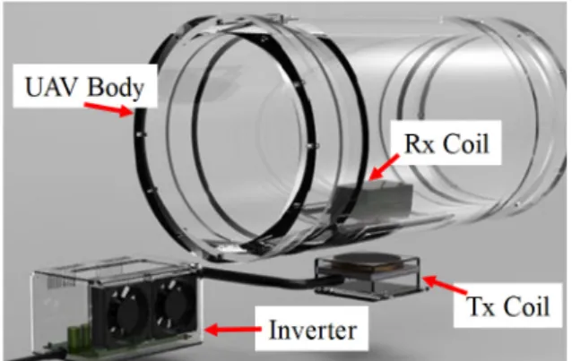
To transfer several hundred Watts or more of power with high efficiency in a WPT environment within a few centimeters, a magnetic induction-type WPT technology should be used. The magnetic induction-type WPT system in a UAV typically in-cludes an inverter, a resonance matching capacitor, two mag-netically coupled coils, and an AC-DC convertor, as shown in Fig. 2.
Fig. 2. Concept of the wireless power transfer system for unmanned vehicles.
In the WPT system used in this study for a UAV, the air gap from the launch ramp to the UAV is 50 mm, as shown in Fig. 3. The body and the WPT coil case is made of aluminum, similar to the body of the UAV. The skin depth of the aluminum at 110 kHz is 247.25 μm, and the thickness of the aluminum coil case is 3 mm. Therefore, the magnetic field generated by the WPT coil cannot affect the inside of the UAV where the other systems are located.
For miniaturization, the inverter for supplying AC power is located at the bottom of the source coil. The rectifying circuits are directly mounted on the body of the UAV to optimize space.
Conventionally, the size of the transmitting and receiving coils needs to be small because of the limited space in UAVs. However, the small size and the long distance between the transmitting and the receiving coils mean that the coupling co-efficient is also small, which can reduce the power transfer effi-
Fig. 3. Configuration of wireless power transfer system for un-manned vehicle.
the diminution of the power transfer efficiency. The geometrical parameters of the conventional WPT coil 1 are shown in Table 1. The material properties of the WPT system for UAVs are presented in Table 2.
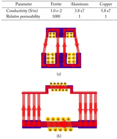
When the highly permeable ferrite is designed with a convex shape, its magnetoresistance becomes lower than that of planar ferrite. In the convex configuration, the ferrite acts as a shaped magnetic field in resonance (SMFIR), which forms a magnetic flux generated by the magneto motive force of the coil along the ferrite with a low magnetic reluctance [10]. A schematic illus-trating the concept of the magnetic field formed by the SMFIR is shown in Fig. 5. As a result of this design, the magnetic flux generated by the current flowing in the transmitting part is tightly linked to the receiving part.
However, when the size of the coil is much smaller than the distance between the two coils, the coupling coefficient (K) is limited. The size of the conventional coil 1 is shown in Table 1.
The vertical direction of the magnetic flux generated by the source coil (or load coil) is captured by the load coil (or source coil) ferrite. The narrow effective area of the ferrite is shown in Fig. 4. The magnetic flux cannot link the opposite coil, thus
Fig. 4. Over all view of conventional WPT system 1 for UAVs.
Parameter Ferrite Aluminum Copper
Conductivity (S/m) 1.0 e-2 3.8 e7 5.8 e7
Relative permeability 1000 1 1
(a)
(b)
Fig. 5. Schematic of the shaped magnetic field with a conventional coil (b) and the proposed toroidal coil (a) using a ferromag-net.
causing the WPT coil system to have a low coupling coefficient. For higher power transfer efficiency, a broader effective area of ferrite is needed.
2. Conventional WPT Coil 2 for a Cordless Umbilical Connector of UAVs
A conventional WPT coil 2 [9] has a loop coil and a ferro-magnetic material with resonance matching capacitance. As shown in Table 1, the conventional WPT system 2 has a larger coil size to increase the coupling coefficient. As the effective area increases, the volume of the coil system also greatly increas-es (Fig. 6).
Fig. 6. Overall view of the conventional WPT system 2 for UAVs.
(a)
(b)
(c)
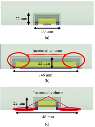
Fig. 7. Application of (a) conventional WPT system 1. (b) conven-tional WPT system 2. (c) proposed toroidal-shaped WPT system.
inside the craft to protect against external impact. Therefore, the coil system should not require an increased volume. Other-wise, it cannot be applied as a UAV WPT system because any increase in the volume of the WPT system limits the load of other devices in the UAV, as shown in Fig. 7(b).
3. Proposed Toroidal-Shaped Coil for Cordless Umbilical Con-nector of UAVs
The proposed toroidal-shaped coil has a transversely wound coil and a wing-shaped ferrite. The toroidal-shaped coil is wound the same as a solenoidal coil, as shown in Fig. 5. The
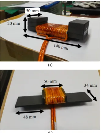
Fig. 8. Overall view of the proposed toroidal-shaped WPT coils for UAVs.
size of the proposed toroidal-shaped coil is listed in Table 1. The volume of the transmitting coil is the same as that of the conventional coil system 1.
Unlike its interior, the exterior surface of the UAV can be easily used without spatial limitation. To take advantage of the unused surface area, the wing-shaped ferrite was designed with a thin flat bar shape, as shown in Fig. 8.
The wing-shaped ferrite can minimize the use of the internal space of UAVs and at the same time widen the effective area of the ferrite. The proposed coil can be embedded into the UAV, as shown in Fig. 7(c). The increased area of the proposed coil system is much smaller than that of the conventional coil 2. The proposed coil can increase the coupling coefficient without af-fecting the volume inside the UAV.
The increased effective area of ferrite can also reduce reluc-tance. That is, when the WPT coil system has a broader effec-tive area of ferrite, the reluctance of the WPT coil system is reduced. The proposed toroidal coil maximizes the effective area of ferrite, which can increase the coupling coefficient with a minimal increase in space.
III.SIMULATION OF THE WPTSYSTEM FOR A
CORDLESS UMBILICAL CONNECTOR OF UAVS
1. Simulation Setup
In the simulation, the operating frequency was set to 110 kHz, and a sinusoidal current flowed through the transmitting coil for a 300-W power transfer. To design the receiving and transmitting coils of the WPT system, a finite element analysis-based magnetic field simulation was used (ANSYS Maxwell Simulation; ANSYS Inc., Canonsburg, PA, USA).
The simulations were conducted under three conditions: a conventional WPT coil 1, a conventional WPT coil 2, and the proposed toroidal-shaped coil. Fig. 9 shows the overall simula-
Fig. 9. Overall setup for the simulation.
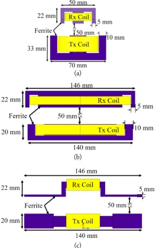
tion setup for each coil. The geometrical parameters of each coil system are shown in Table 1. The cross-section of the conven-tional coils and the proposed toroidal-shaped coil are illustrated in Fig. 10.
(a)
(b)
(c)
Fig. 10. Side view of the simulation configuration. (a) Convention-al WPT coil system 1, (b) conventionConvention-al WPT coil system 2, and (c) proposed toroidal-shaped coil system.
proximity effect were neglected. To compare the power transfer efficiency, a circuit simulation was performed. The values of the compensation capacitors of the transmitting and receiving coils were determined on the basis of the operating frequency, and a full bridge rectifier and a smoothing capacitor were constructed.
2. Comparison of Power Transfer Efficiencies
The input power of the system is the power supplied from the DC power supply in front of the transmitting coil. The power delivered to the receiver is measured at the back of the receiving coil. The overall system efficiency is the ratio of the power delivered to the load to the system input power. The simulation results are shown in Table 4. The conventional coil system 1 has low power transfer efficiency because of the differ-ent sizes of the transmitting and receiving coils. The aluminum Table 3. Electrical parameters of the conventional coils (CC) and
the proposed toroidal-shaped coil
Parameter CC 1 CC 2 Proposed coil Tx resistance (mΩ) 5.58 13.25 24.19 Rx resistance (mΩ) 5.51 7.89 11.23 Tx self-inductance (μH) 64.61 181.0 31.15 Tx matching capacitor (nF) 32.39 11.56 67.20 Rx self-inductance (μH) 6.01 2.76 9.90 Rx matching capacitor (nF) 348.20 758.48 211.33 Mutual inductance (μH) 0.28 0.67 3.71 Coupling coefficient 0.014 0.030 0.21 Resonance frequency (kHz) 110 110 110 Table 4. Simulated input, output power, and power transfer
effi-ciency of conventional coils (CC) and the proposed toroi-dal-shaped coil
Parameter CC 1 CC 2 Proposed
coil
Input power (W) 633.7 467.6 365.7
Output power (W) 299.9 303.1 309.5
case around the receiving coil decreases the coupling coefficient by canceling the magnetic flux generated by the eddy currents on the aluminum.
The conventional coil system 2 is found to have increased power transfer efficiency in comparison with the conventional coil system 1 because the transmitting and receiving coils were similar in size. The canceling magnetic field from the aluminum case around the receiving coil has lesser effect on the coupling coefficient between the two coils.
The wing ferrite can capture the magnetic flux generated by the opposite coil, thus increasing the coupling coefficient. By using the wing ferrite, the proposed toroidal-shaped coil in-creased the power transfer efficiency by 37.3%. The wing ferrite, which is included in the proposed toroidal-shaped coil system, has a dramatic effect on the power transfer efficiency of the WPT system, with minimal additional space requirements.
IV.MEASUREMENT OF THE WPTSYSTEM FOR A
CORDLESS UMBILICAL CONNECTOR OF UAVS
The power transfer efficiency of the proposed toroidal-shaped coil was measured for comparison with the simulated results. As shown in Fig. 11, a 300-W WPT coil system was designed and implemented to experimentally verify the effectiveness of the proposed toroidal-shaped coil. A Litz wire was used for the coil
(a)
(b)
Fig. 11. Manufactured toroidal-shaped coil. (a) Transmitting coil and (b) receiving coil.
Fig. 12. Configuration of the WPT system for measurement.
Table 5. Comparison of the simulated and measured input, output power, and power transfer efficiency
Parameter Simulated Measured
Input power (W) 365.7 360.3
Output power (W) 309.5 302.7
Power transfer efficiency (%) 84.6 84.0 winding to increase the power transfer efficiency by reducing the resistance of the proposed toroidal-shaped coil.
The resonance frequencies of the transmitting and receiving coils were set to 110 kHz as in the simulations. Consistent with the simulations, the power delivered to the load was 300 W, and the voltage targeted was at 28 V. Therefore, the resistance of the electronic load was set to 2.55 Ω.
The size of the coils and the distance between the source and the receiving coils were the same as those in the simulation en-vironment. The overall coil configuration of the experiment is presented in Fig. 12. The case of the source and receiving coils was made with aluminum, which was also used for the case of the UAV. The air gap consisted of acrylic, which did not affect the generation or linkage of the magnetic field. A full-bridge inverter was used to convert DC power to AC power.
Table 5 shows the input power, output power, and efficiency calculated by measuring the current and the voltage at each point. The measurement data correlated well with the simula-tion data. The proposed toroidal- shaped coil system dramati-cally increased the power transfer efficiency.
V.CONCLUSION
In this study, we propose a toroidal-shaped coil system using a wing-shaped ferrite to overcome the reduced efficiency result-ing from the small coil size of conventional WPT systems, which is their inherent limit, for UAVs. The design and analysis of the proposed toroidal-shaped coil were performed, and com-parisons with other coil systems were conducted using simula-tions and measurements. The simulation results were in good agreement with the results obtained by measurement.
REFERENCES
[1] K. D. Mullens, E. B. Pacis, S. B. Stancliff, A. B. Burmeister, and T. A. Denewiler, "An automated UAV mission sys-tem," Space and Naval Warfare Systems Command, San Die-go, CA, 2003.
[2] M. K. Furrutter and J. Meyer, "Small fuel cell powering an unmanned aerial vehicle," in Proceedings of IEEE AFRICON, Nairobi, Kenya, 2009, pp. 1–6.
[3] K. Michals, "UAV power supply maintenance method," 2012; https://www.flickr.com/photos/rocbolt/7187520615 /in/photostream.
[4] A. Kurs, A. Karalis, R. Moffatt, J.D. Joannopoulos, P. Fish-er, and M. Soljacic, "Wireless power transfer via strongly coupled magnetic resonances," Science, vol. 317, no. 5834, pp. 83–86, 2007.
Jaehyoung Park
received his M.S. degree from the Korea Advanced Institute of Science and Technology (KAIST), Dae-jeon, Korea, in 2014. He is currently completing his Ph.D. degree in KAIST. His current research inter-ests include the electromagnetic compatibility issues in wireless power transfer.
nal of Electromagnetic Engineering and Science, vol. 17, no. 4,
pp. 208–220, 2017.
[8] W. Huang and H. Ku, "Analysis and optimization of wire-less power transfer efficiency considering the tilt angle of a coil," Journal of Electromagnetic Engineering and Science, vol. 18, no. 1, pp. 13–19, 2018.
[9] J. Kim, J. Kim, S. Kong, H, Kim, I. S. Suh, N. P. Suh, D. H. Cho, J. Kim, and S. Ahn, "Coil design and shielding methods for a magnetic resonant wireless power transfer system," Proceedings of the IEEE, vol. 101, no. 6, pp. 1332– 1342, 2013.
[10] J. Shin, S. Shin, Y. Kim, S. Ahn, S. Lee, G. Jung, S. J. Jeon, and D. H. Cho, "Design and implementation of shaped magnetic-resonance-based wireless power transfer system for roadway-powered moving electric vehicles,"
IEEE Transactions on Industrial Electronics, vol. 61, no. 3,
pp. 1179–1192, 2014.
Jonghoon Kim
received his Ph.D. degree from the Department of Electrical Engineering of the Korea Advanced Insti-tute of Science and Technology (KAIST), Daejeon, Korea, in 2003. His master and doctoral theses were focused on the reduction of electromagnetic interfer-ence (EMI) from a high-speed digital system. After receiving his Ph.D. degree, he joined the Memory Division of Samsung Electronics, Korea, in 2003. Since then, he gained experience in the standardization for DDR3/DDR4 memory and in the design of semiconductor test hardware for high-speed memory. He moved to KAIST in 2010 to become a research professor of the Division of Future Vehicle. Since joining KAIST, he gained experience in module/component design for automobile and in electromagnetic com-patibility design of a wireless power transfer system for electric vehicles. He became the president of EMC Doctors Inc. in 2017. His current research interests include signal integrity, power integrity, and EMI/EMC of high-speed digital systems and the analysis and design of WPT systems.
Yujun Shin
received his B.S. degree in electrical engineering from Inha University, Incheon, Korea, in 2016. He is currently completing his Ph.D. degree at the Ko-rea Advanced Institute of Science and Technology. His main research interests are in wireless power transfer systems for electric vehicle systems.
Bumjin Park
received his B.S. degree in electrical engineering from Chungnam National University, Daejeon, Korea, in 2015 and his M.S. degree from the Korea Advanced Institute of Science and Technology (KAIST), Daejeon, Korea, in 2017. He is currently completing his Ph.D. degree at KAIST. His current research interests include magnetic material and magnetic energy harvesting.
Won-Seok Kim
received his B.S. degree in Information and Com-munication engineering from Daegu University, Daegu, Korea, in 2001. Now, he belongs to WIS-TEK Co. Ltd. His current research interests are wire-less power transmission, radar system, and many other RF systems.
Seok-Jong Cheong
received his B.S. degree in electronic engineering from Yonsei University, Seoul, Korea, in 1980 and his M.S. degree in computer science at the Korea Advanced Institute of Science and Technology in 1996. He worked for Guidance and Control Part of the missile system in ADD, Daejeon, Korea, from 1980 to 1998. Since 1999, he gained various experi-ences in commercial fields, such as geolocation sys-tems, cellular mobiles, ETCS, and wearable devices, among others. Now, he belongs to WISTEK Co. Ltd. His current research interests are wireless power transmissions, radar systems, and other RF systems.
Seungyoung Ahn
received his B.S., M.S., and Ph.D. degrees at the Korea Advanced Institute of Science and Technolo-gy (KAIST), Korea, in 1998, 2000, and 2005, re-spectively. He is currently an associate professor at KAIST. His research interests are WPT system design and electromagnetic compatibility design for electric vehicles and digital systems.