Korean J. Mater. Res.
Vol. 29, No. 9 (2019)
519
Fabrication and Characterization of Spherical Carbon-Coated Li
3V
2(PO
4)
3Cathode Material by Hydrothermal Method with
Reducing Agent
Jung-In Moon
1and Jeong-Hwan Song
2†1Department of Materials Engineering, Graduate School of PaiChai University, Daejeon 35345, Republic of Korea
2Department of Materials Science and Engineering, PaiChai University, Daejeon 35345, Republic of Korea
(Received July 19, 2019 : Revised August 22, 2019 : Accepted August 27, 2019)
Abstract
Spherical Li3V2(PO4)3 (LVP) and carbon-coated LVP with a monoclinic phase for the cathode materials are synthesized by a hydrothermal method using N2H4 as the reducing agent and saccharose as the carbon source. The results show that single phase monoclinic LVP without impurity phases such as LiV(P2O7), Li(VO)(PO4) and Li3(PO4) can be obtained after calcination at 800 oC for 4 h. SEM and TEM images show that the particle sizes are 0.5~2 µm and the thickness of the amorphous carbon layer is approximately 3~4 nm. CV curves for the test cell are recorded in the potential ranges of 3.0~4.3 V and 3.0~4.8 V at a scan rate of 0.01 mV s–1 and at room temperature. At potentials between 3.0 and 4.8 V, the third Li+ ions from the carbon-coated LVP can be completely extracted, at voltages close to 4.51 V. The carbon-coated LVP exhibits an initial specific discharge capacity of 118 mAh g–1 in the voltage region of 3.0 to 4.3 V at a current rate of 0.2 C. The results indicate that the reducing agent and carbon source can affect the crystal structure and electrochemical properties of the cathode materials.Key words
Li3V2(PO4)3, hydrothermal, N2H4, saccharose, cathode material.1. Introduction
Li-ion batteries have been widely used for portable electronic devices and hybrid electric vehicles because of their high energy densities. Among the known cathode materials, either LiCoO
2or LiMnO
2with a layered structure is used in most commercial Li ion secondary batteries.
1-4)These materials are industry standard, but they exhibit short lifetimes and low energy densities, and they are expensive and can possibly create safety hazards.
Currently, olivine-structured phosphate systems such as Li
3V
2(PO
4)
3(LVP)
5-9)and doped-Li
3V
2(PO
4)
310-15)have attracted wide attention as promising next-generation materials owing to their non-toxicity, low cost, and structural stability. They are also environmentally friendly and exhibit good cycle performance. The monoclinic LVP material is of particular interest because it has good ion mobility, high operating voltage, high theoretical capacity (197 mAh g
−1), and good thermal stability. However, the
LVP material has lower electronic conductivity and lithium diffusivity as LiFePO
4owing to the polarization of the V-O bond, which greatly restricts its practical application for Li ion batteries. The lower electrical conductance of LVP has been solved to some extent by using doping materials such as transition metal ions in the vanadium sites and alkali ions in the lithium sites.
Additionally, although carbon composite LVP or carbon- coated LVP materials obtained by using citric acid, sucrose, humic acid, and phenolic resin as carbon source is regarded as an effective way of improving the electrochemical performance, it is rather difficult to encapsulate LVP homogeneously with a carbon shell during the formation of LVP at high temperatures.
16-20)The most common methods of obtaining LVP are solid-state techniques using hydrogen atmosphere or carbon as reducing agents. In general, the synthesis of LVP occurs through the reduction of V
5+to V
3+, and a carbon coating is fabricated by a carbothermal reduction
†Corresponding author
E-Mail : [email protected] (J.-H. Song, PaiChai Univ.)
©Materials Research Society of Korea, All rights reserved.
This is an Open-Access article distributed under the terms of the Creative Commons Attribution Non-Commercial License (http://creative- commons.org/licenses/by-nc/3.0) which permits unrestricted non-commercial use, distribution, and reproduction in any medium, provided the original work is properly cited.
prepare spherical monoclinic LVP as a cathode material by using N
2H
4·H
2O as the reducing agent. In order to overcome the poor conductivity, we directly prepared carbon-coated LVP by a hydrothermal method using saccharose as the carbon source. The structure, composition, morphology, and electrochemical performance were compared between carbon-coated LVP and pure LVP.
2. Experimental
2.1 Materials and preparation
In order to prepare 0.01 mol stoichiometric Li
3V
2(PO
4)
3, V
2O
5(99 %), H
3PO
4(solution, 85 %) and LiOH (98 %) were quantitatively employed as the starting materials.
The precursor was prepared as follows. V
2O
5(0.01 mol) was dissolved in 70 mL of distilled water under magnetic stirring at approximately 75
oC until a clear solution was formed. Then, N
2H
4·H
2O (solution, 80 %) was added as a reducing agent and in quantities three times that of V
2O
5to occur reducing reaction. As the amount of reducing agent N
2H
4·H
2O is increased steadily, the product forms gradually and the phase evolution V
2O
5→ VO
2→ V
2O
3occurs through the following route:
2V
2O
5+ N
2H
4·H
2O → 4VO
2+ N
2+ 3H
2O (1) 4VO
2+ N
2H
4·H
2O → 2V
2O
3+ N
2+ 3H
2O (2) H
3PO
4and a solution of LiOH were added sequentially dropwise into the abovementioned solution. The resulting solution was vigorously stirred at a holding temperature of 75
oC for 1h. Finally, this mixture was transferred into a 110 mL Teflon container and the container was sealed.
Then, the autoclave was maintained at 200
oC for 24 h to obtain a green precursor. The precursor obtained by hydrothermal treatment was separated and washed three times with distilled water and ethanol and finally dried at 80
oC for 24 h. The dried precursor was transferred to a tube furnace equipped with a flowing N
2atmosphere and heat treated at a temperature of 700~800
oC for 4 h.
In the same time, the carbon-coated LVP was prepared
field-emission scanning electron microscopy (FE-SEM) (Sirion, FEI, Netherland) and the presence of the carbon layer was confirmed through transmission electron microscopy (TEM) (JEOL Ltd, Japan). The quantitative analysis of the synthesized LVP was carried out by inductively coupled plasma-atomic emission spectroscopy (ICP-AES) (Thermo, ICAP 6000). Fourier transform- infrared (FT-IR) spectrophotometry (PerkinElmer 100, UK) was used to determine the nature of the bonds in the LVP using the KBr pellet technique in the wavenumber range of 1,500-400 cm
−1. FT-IR samples were prepared by mixing dried LVP with KBr in a 1:10 ratio by weight.
The materials were ground by hand in an agate mortar and pressed into molds by holding for 5 min under a press. X-ray photoelectron spectrometry (XPS, MultiLab.
ESCA 2000) was used to evaluate the chemical state and electronic state.
The cathode of the two-electrode electrochemical cell was fabricated by blending the prepared powder with carbon black (Super P) and PVDF (polyvinylidene difluoride) binder in a weight ratio of 80:10:10 in 1- methy-2-pyrrolidone (NMP) solvent. The obtained slurry was coated on Al foil and dried at 100
oC for 24 h.
Lithium foil (99 %) was used as the anode. The separator was Celgard polypropylene (PP). The electrolyte was composed of 1 M LiPF
6dissolved in a solution of ethylene carbonate (EC)/dimethyl carbonate (DMC)/ethylmethyl carbonate (EMC) in the volume ratio 1:1:1. The coin- cells of CR2032 were assembled in an argon-filled glove box (H
2O and O
2< 0.3 ppm). The cyclic voltammogram (CV) curves for the above test cell were recorded in the potential ranges 3.0-4.8 V at a scan rate of 0.01 mV s
−1and at room temperature. Cycling tests were carried out at a charge-discharge rate of 0.2 C between 3.0~4.3 V.
3. Results and Discussion
Fig. 1 shows the XRD patterns of the hydrothermally
synthesized pure LVP and carbon-coated LVP to
determine the crystal structure and purity phase. It can be
seen from the figure that their phases are similar to each other. After the hydrothermal reaction, the precursors exhibit intermediate phases such as LiV(P
2O
7), Li(VO) (PO
4) and Li
3(PO
4). The diffraction peaks of the LVP powders are mainly assigned as indicated in previous reports.
18,21)The peaks exhibit good crystallinity at relatively lower temperatures as compared to solid-state reactions, as shown in Fig. 1. However, the product calcined at 700
o
C still contained a secondary phase Li
3(PO
4). The LVP powders calcined at 800
oC are indexed to a single-phase monoclinic structure with a space group P2
1/ n. The XRD patterns of the carbon-coated LVP powders calcined at 800
oC correspond to a single-phase monoclinic structure without any secondary phase. The carbon phase was not detected by XRD, because the amount was comparatively small to 5 % or an amorphous phase. Using ICP, it was determined that the quantitative ratio of Li, V, and P was 37, 24, and 36 at%, respectively.
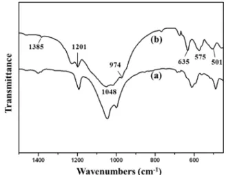
The absorption mode of the FT-IR in the carbon-coated
LVP obtained from the VO
6and PO
4bands is shown in Fig. 2.
24)It is clear that the FT-IR spectra of both samples are similar. As shown in Fig. 2, the bands at 501, 635, and 974 cm
−1can be assigned to the vibration of bonds between V
3+and O
2−in the VO
6octahedra. The bands at 950 and 760 cm
−1that correspond to the presence of V
5+ions in VO
6octahedra were not observed. These results indicate that the V
5+in V
2O
5is completely reduced to V
3+by the reducing agent. The bands at 575 and 1048 cm
−1suggest the presence of P-O bonds of PO
4tetrahedra.
The infrared bands in the range of 1,150~1,250 cm
−1can be attributed to the stretching vibrations of PO
4units.
XPS was used to determine the compositions and valence of elements in the carbon-coated LVP powder.
As shown in Fig. 3, the C 1s core peak occurs at a binding energy of 285.0 eV originating from C-C bond generated carbon obtained from the decomposition of saccharose. This implies that the residual carbon exists in LVP. The O 1s core level shows a single peak with a binding energy of 531.8 eV, which is attributed to the oxygen atoms of (PO
4)
3−. The P 2p peak appeared at 134.1 eV, and a Li 1s peak have appeared at around 56.1 eV, although it could not be clearly detected here. The V 2p core peak of the carbon-coated LVP appears at 517.5 eV and matches well with the peak observed in V
2O
3. Furthermore, the oxidation state of V is estimated to be +3.
14,24)Thus, it is clear that carbon is present because of the decomposition of saccharose and V
5+is reduced to V
3+for the obtained carbon-coated LVP powder.
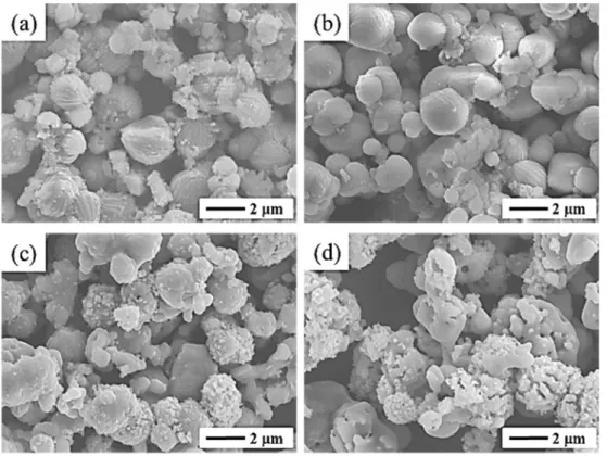
The morphology of both samples is shown in the SEM images in Fig. 4. Both precursor samples have a powder size of approximately 0.5~2 μm with a spherical morphology. After calcinations at 800
oC, the LVP formed a network of secondary particles, which maintained the initial morphology without the growth of spherical
Fig. 2. FT-IR spectra of carbon-coated Li3V2(PO4)3 powders (a) as- prepared and (b) heat treated at 800 oC for 4 h.Fig. 1. X-ray diffraction patterns of (a) Li3V2(PO4)3 and (b) carbon- coated Li3V2(PO4)3 prepared by hydrothermal method.
that compositional transitions occurred to the V
2(PO
4)
3structure, associated with the V
4+/V
5+redox couple.
17)Although the CV curve of carbon-coated LVP is similar with LVP, the carbon-coated LVP exhibits sharper and more symmetrical current peaks than pure LVP. The results indicate that the carbon coating layer helps improve the electrochemical performance.
Fig. 7 shows an initial charge-discharge profile of the pure LVP and the carbon-coated LVP cells in the potential range from 3.0 to 4.3 V at a rate of 0.2 C. The voltage profiles exhibit three charge plateaus and the corresponding three discharge ones, which corresponds to three compositional regions of L
3-xV
2(PO
4)
3, that is, x = 0.0–0.5, x = 0.5–1.0, and x = 1.0–2.0. The charge-discharge
Fig. 4. FE-SEM images of (a, c) Li3V2(PO4)3 and (b, d) carbon-coated Li3V2(PO4)3 prepared by hydrothermal method. The samples shown in (c) and (d) were heat treated at 800 oC for 4 h.
Fig. 3. XPS spectrum of carbon-coated Li3V2(PO4)3 heat treated at 800 oC for 4 h.
behavior of the LVP electrode may be interpreted by the CV curve in the voltage range of 3.0~4.3V shown in Fig.
6. Pure LVP has an initial discharge capacity of 101 mAh g
−1, whereas that for the carbon-coated LVP is 118 mAh g
−1. Because of the low conductivity and
polarization of the pure LVP, it will have a low discharge capacity. However, because of the high conductivity of lithium in the carbon-coated LVP, a rapid cycle of reversible elimination-insertion of Li ions occurred, which facilitates a high discharge capacity.
4. Conclusions
Pure LVP and carbon-coated LVP cathode materials were synthesized by a hydrothermal treatment using N
2H
4·H
2O as a reducing agent and saccharose (C
12H
22O
11) as a carbon source. The thermal treatment following the hydrothermal method was performed at a lower temperature than that of the conventional solid-state reactions. The obtained LVP powders showed uniform and spherical morphology with powder sizes of approximately 0.5~2.0 μm. This work shows that powders were obtained for pure LVP and carbon-coated LVP with a monoclinic phase at 800
oC for 4 h without any morphological change.
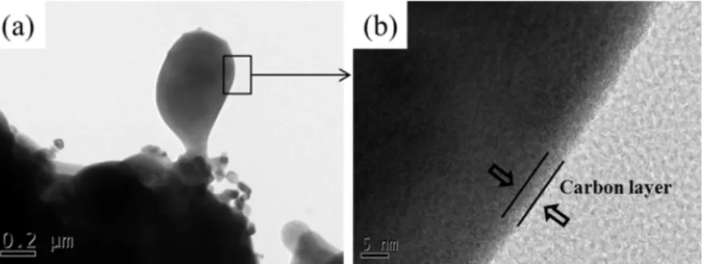
TEM image confirmed that the LVP powder were
Fig. 5. TEM image of (a) carbon-coated Li3V2(PO4)3 powder and (b) uniform coverage of amorphous carbon layer on the surface of carbon- coated Li3V2(PO4)3.Fig. 7. Initial charge~discharge profiles of Li3V2(PO4)3 (dashed line) and carbon-coated Li3V2(PO4)3 (solid line) at 0.2 C rate in the voltage range of 3.0~4.3 V at room temperature.
Fig. 6. CV curves for Li3V2(PO4)3 (dashed line) and carbon-coated Li3V2(PO4)3 (solid line) cathode in the potential range (a) 3.0~4.3 V and (b) 3.0~4.8 V at a scan rate of 0.01 mV s−1 and at room temperature.
carbon-coated LVP cathode materials exhibited enhanced discharge capacity and cycle performance.
Acknowledgement
This research was supported by Nano·Material Technology Development Program through the National Research Foundation of Korea(NRF) funded by the Ministry of Science, ICT and Future Planning(2017- 0628010).
References
1. D. Guyomard and J.M. Tarascon, J. Electrochem. Soc., 139, 937 (1992).
2. C. D. W. Jones, E. Rossen and J. R. Dhan, Solid State Ionics, 68, 65 (1994).
3. H. Y. Xu, S. Xie, N. Ding, B. L. Liu, Y. Shang and C.
H. Chen, Electrochim. Acta, 51, 4352 (2006).
4. K. Ozawa, Solid State Ionics, 69, 212 (1994).
5. J. Gaubicher, C. Wurm, G. Goward, C. Masquelier and L.
Nazar, Chem. Mater., 12, 3240 (2000).
6. S. C. Yin, H. Grondey, P. Strobel, H. Huang and L. F.
Nazar, J. Am. Chem. Soc., 125, 326 (2003).
7. S. C. Yin, H. Grondey, P. Strobel, M. Anne and L. F.
196, 1494 (2011).
14. M. M. Ren, Z. Zhou, Y. Z. Li, X. P. Gao and J. Yan, J.
Power Sources, 162, 1357 (2006).
15. D. Ai, K. Liu, Z. Lu, M. Zou, D. Zeng and J. Ma, Electrochim. Acta, 56, 2823 (2011).
16. H. Huang, S. C. Yin, T. Kerr, N. Taylor and L. F. Nazar, Adv. Mater., 14, 1525 (2002).
17. Q. Q. Chen, J. M. Wang, Z. Tang, W. C. He, H. B. Shao and J. Q. Zhang, Electrochim. Acta, 52, 5251 (2007).
18. A. P. Tang, X. Y. Wang and Z. M. Liu, Mater. Lett., 62, 1646 (2008).
19. X. C. Zhou, Y. M. Liu and Y. L. Guo, Solid State Commun., 146, 261 (2008).
20. M. M. Ren, Z. Zhou, X. P. Gao, W. X. Peng and J. P.
Wei, J. Phys. Chem. C, 112, 5689 (2008).
21. X. J. Zhu, Y. X. Liu, L. M. Geng, L. B. Chen, H. X. Liu and M. H. Cao, Solid State Ionics, 179, 1679 (2008).
22. X. J. Zhu, Y. X. Liu, L. M. Geng and L. B. Chen, J.
Power Sources, 184, 578 (2008).
23. C. Sun, S. Rajasekhara, Y. Dong and J. B. Goodenough, ACS Appl. Mater. Interfaces, 3, 3772 (2011).
24. Z. Chen, C. Dai, G. Wu, M. Nelson, X. Hu, R. Zhang, J. Liu and J. Xia, Electrochim. Acta, 55, 8595 (2010).
25. J. S. Huang, L. Yang and K. Y. Liu, Mater. Lett., 66, 196 (2012).