• 검색 결과가 없습니다.

Conceptual Design of an HTS Motor for Future Electric Aircraft

N/A
N/A
Protected

Academic year: 2021

Share "Conceptual Design of an HTS Motor for Future Electric Aircraft"

Copied!
9
0
0

로드 중.... (전체 텍스트 보기)

전체 글

(1)

1. Introduction

* Corresponding Author: [email protected]

+ 이 논문은 2019년-2020년도 창원대학교 연구비에 의하여 연 구되었음.

Manuscript received July 15, 2020 / revised August 05, 2020 / accepted August 12, 2020

1) 창원대학교 전기공학과, 제1저자 2) 창원대학교 전기공학과, 제2저자 3) 창원대학교 전기공학과, 제2저자 4) 창원대학교 전기공학과, 교신저자

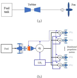
Number of air traffic passengers has doubled over the last 15 years and is expected to grow at the same rate of growth over the next decades (Martin, 2012). Most aircrafts are equipped with turbo engine-based propulsion systems. However, the turbo engine-base propulsion systems have inherent drawbacks of low efficiency (less than 50%), high emission gas, and large

차세대 전기 항공기를 위한 HTS 모터의 개념 설계

+

1)

(Conceptual Design of an HTS Motor for Future Electric Aircraft)

레 딘 브 엉 1) , 남 기 동 2) , 이 석 주 3) , 박 민 원 4)*

(Dinh-Vuong Le, Gi-Dong Nam, Seok-Ju Lee, and Minwon Park)

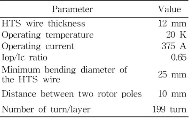
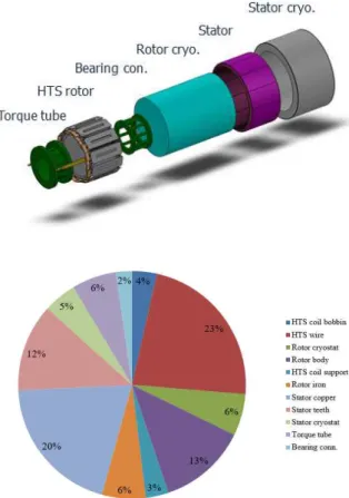
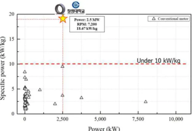
요 약 기존의 전기 모터는 큰 중량과 부피의 단점으로 항공기 적용에 적합하지 않다. 고온 초 전도 (High-Temperature Superconducting: HTS) 모터는 전류 밀도와 자기장 밀도가 높으며 손실 이 적어 일반 전기모터와 비교하여 크기와 무게를 크게 줄일 수 있다. 본 논문은 미래 항공기 전기 추진용 HTS 모터의 개념 설계 및 해석 결과를 제시한다. 회전속도가 7,200 RPM인 2.5 MW 용량의 HTS 모터를 설계하고 무게 대비 출력 비(kW/kg)를 분석하였다. HTS 모터 계자코일 (Field Coil) 의 운전온도는 LH

2

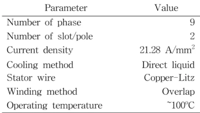
(Liquid Hydrogen) 냉각을 고려하여 20K을 선정하였다. 고정자 권선 (Stator Winding)은 다상 구성 (Multi-Phase Configuration)으로 연결하였고 와전류 (Eddy Current) 손실을 최소화하기 위해 Litz 선을 사용하였다. 결과적으로 모터의 무게 대비 출력 비는 약 18.67 kW/kg으 로 기존 모터보다 훨씬 높음을 확인하였다.

핵심주제어: 항공기 추진 시스템, 전기 항공기 전기 모터, HTS 모터, 초전도 모터

Abstract Conventional electric motors are not suitable for aircraft because of their large size and weight. High-temperature superconducting (HTS) motors have high current density, high magnetic field density, and low loss, so they can significantly reduce the size and weight compared to general electric motors. This paper presents the conceptual design and analysis results of HTS motors for electric propulsion in future aircraft. A 2.5 MW HTS motor with a rotational speed of 7,200 RPM was designed and the specific power (kW/kg) was analyzed. The operating temperature of the field coil of the HTS motor is 20K in consideration of LH2 cooling.

The stator winding were connected in a multi-phase configuration and Litz wires were used to minimize eddy current losses. As a result, it was confirmed that the specific power of the motor is about 18.67 kW/kg, which is much higher than that of the conventional electric motor.

Keywords: Aircraft propulsion system, Electric aircraft, Electric motor, HTS motor, Superconducting motor

(2)

noise (Naayagi, 2013; Epstein, 2014; European Environment Agency, 2016; Bolarn et al., 2018). Electric propulsion systems have been studied for decades to overcome the deficiencies of the existing turbo engine-based propulsion system (Gohardani et al., 2011;

Sarlioglu and Morris, 2015; Kim et al., 2018).

However, the conventional motors of the electric propulsion system have a low specific power (about 5 kW/kg), which is too heavy for use in large aircraft, therefore, the largest power capacity of the conventional electric propulsion system is only 260 kW for the single-seat aircraft so far (Brelje and Martins, 2019).

High-temperature superconducting (HTS) machines have recently been extensively researched for wind generators, ship propulsion motors, power application, and are in the stage of practical application (Tuvdensuren et al., 2019a, 2019b; Lee et al., 2019). The advantage of HTS machines is to greatly reduce the volume and weight of machines. Therefore, the HTS motor is expected as a solution to increase the specific power of conventional motors in electric propulsion systems. Several conceptual designs of the HTS motors have been studied and showed a remarkable achievement of the specific power (Jansen et al., 2018; Welstead et at., 2016).

Siemens presented a conceptual design of a 10 MW HTS generator for an electric propulsion system with an specific power of 22 kW/kg (Kühn, 2019). In order to reduce the size and weight of the motor, the HTS wire used in such designs have the thickness of 0.065 mm which does not have the substrate layer (Scheidler et al., 2018).

Therefore, it can lead into many questions about the reliability of the HTS wire, especially when the HTS wire of the aircraft

propulsion system operates at high rotating speed, torque, magnetic field, and power density.

This paper presents a conceptual design and analysis results of an HTS motor for future electric aircrafts. The HTS wire of a 2.5 MW HTS motor has the width of 12 mm and the thickness of 0.1 mm that is a common commercial HTS wire. No-insulation (NI) HTS coils were used as the field coil of the motor. The rotor body was made of lightweight aluminum alloy with good mechanical performance. To increase the magnetic field density, the iron core was added to the rotor part. The stator coils were wound with an overlap-2 layer winding method and 9-phase configurations were used to increase reliability and fault current capacity.

The HTS motor was modeled, simulated, and analyzed by the finite-element method (FEM) simulation using the MagNET program. The HTS wire was modelled as a perfect. The operating current and its margin were selected based on the magnetic field dependent properties of the HTS wire. The results show that the copper, teeth and shield of the stator account for more than 65% of the weight of the motor, and these are the three heaviest components of the HTS motor.

For the designed 2.5 MW HTS motor, it has a specific power of 18.67 kW/kg, which is four times higher than conventional motors.

These results can be effectively used for the research and development of HTS motors for future electric aircraft.

2. Design of a 2.5 MW HTS Motor 2.1 Configuration of an Electric Propulsion

System using HTS Motor

(3)

Propulsion systems of aircraft with single or twin aisles require several tens of MW of power capacity. In an electric propulsion system, propellers or fans are driven by several HTS motors to generate the thrust of the aircraft. Since weight is a sensitive parameter to the performance of the aircraft, the HTS motor and other components of the propulsion system must have a high specific power (kW/kg). Liquid hydrogen (LH 2 ) is used to cool the HTS wire. As shown in Fig.

1, the hydrogen gas used to cool the HTS wire, along with the jet fuel, is burned in a turbo engine to generate power for the aircraft's HTS motors and other electrical systems.

(a)

(b)

Fig. 1 Simplified Block Diagram of an Aircraft Propulsion System;

(a): Conventional Propulsion System;

(b): Electric Propulsion System using HTS Motors

Defining the optimal power capacity of one HTS motor requires extensive research on aircraft structure, operating conditions and aerodynamic performance, which is beyond

the scope of this study. However, since the propulsion system consists of a distributed configuration, the electric motor's power capacity is usually between 1 MW to 5 MW (National Academies of Sciences, 2016).

Therefore, a 2.5 MW HTS motor was the design goal in this study.

In the electric propulsion system, the weight and efficiency of the electric motor are the most two parameters. The efficiency of the electric motor is about 97-98% that is acceptable for the propulsion system.

However, the weight of the conventional motor that has specific power under about 10 kW/kg is too heavy for large aircraft propulsion system. The HTS motor is expected to achieve a specific power higher than 15 kW/kg with the almost same efficiency to overcome the drawback of the conventional motor. The essential of the HTS motor is using the superconducting wire to generate a high magnetic to reduce the size and weight of the HTS motor.

2.2 Rotor Design

The output power of the motor was calculated as equation (1).

 

      (1)

where, k ω is the winding factor, B so is the radial peak magnetic density, A s is the stator electric loading, D is the stator inner diameter, L is the effective length of the motor and n s is the rotating speed.

By increasing of the rotor magnetic field, the volume/size and the motor weight can reduce significantly at a sampe output power.

The configuration of the 2.5 MW HTS

(4)

motor was shown as in Fig. 2. HTS wire was used for the field coil of the motor, LH 2

was used as the coolant for the rotor section, and the operating temperature of the HTS coil was 20 K. The stator part used copper Litz wire, and the water cooling system was used to reduce the size and weight by increasing the current density of the stator wire.

Fig. 2 Structure of the 2.5 MW HTS motor

Fig. 3 Critical Current Property of the HTS Wire

The operating temperature of the stator wire was about 100 o C. The rated rotation speed of the HTS motor is 7,200 RPM and the rated torque is about 3.315 kN∙m. Table 1 shows the detailed specifications of the 2.5 MW HTS motor. In order to control the speed and power of the motor, the voltage and frequency control method through the inverter system was used. The rated voltage

and frequency are 2.5 kV and 720 Hz, respectively.

The field coils have a bending dimeter of 25 mm. The distance between two poles is 10 mm for mechanical support. The total air gap from HTS coil module to the stator was 15 mm. The NI double pancake coils were selected because of improved quench projection and thermal stability (Ralph et al., 2018).

Table 1 Fundamental Parameters of the HTS Motor

Parameter Value

Rated power 2.5 MW

Rated torque 3.315 kN∙m

Rated rotating speed 7,200 RPM

Number of pole 12

Rated voltage (peak) 2.5 kV

Rated frequency 720 Hz

Table 2 Specifications of the Rotor Part

Parameter Value

HTS wire thickness 12 mm

Operating temperature 20 K

Operating current 375 A

Iop/Ic ratio 0.65

Minimum bending diameter of

the HTS wire 25 mm

Distance between two rotor poles 10 mm Number of turn/layer 199 turn

The HTS wire was modeled as a perfect conductor. Based on the temperature and magnetic field dependent properties of the HTS wire provided by the manufacturer, as shown in Fig, 3, the operating current of 375 A was chosen. The margin of the critical current was 35% (Iop/Ic = 0.65). One rotor pole had two layers, each layer had 189 turn.

The rotor body used the Aluminum alloy

material. The minimum thickness of the rotor

(5)

body is 20 mm. The salient pole of rotor used iron-cored to increase the magnetic field.

The specifications of the rotor parts are shown in Table 2.

2.3 Stator Design

The stator coil of the motor consists of a half-slot, double-layered copper winding. The copper windings are exposed to a time-varying high magnetic field generated by the HTS field coils. The Litz wire is used to minimize eddy current losses. The current density of the stator is 21.28 A/mm 2 and the temperature of the stator part is kept stable below 100 o C by the individual liquid cooling system.

Table 3 Specifications of the Stator Part

Parameter Value

Number of phase 9

Number of slot/pole 2

Current density 21.28 A/mm 2 Cooling method Direct liquid

Stator wire Copper-Litz

Winding method Overlap

Operating temperature ~100 o C To avoid the harmonics at the stator voltage due to the magnetic saturation effect of the iron-core, the stator teeth used the non-magnetic material. Since a multi-phase configuration of the stator can increase the reliability and the fault current capacity of the motor (Zheng and Wang, 2016), in this study, a nine-phase structure consisting of three individual power supplies was chosen. Each individual power supply uses a typical three-phase AC system. The specifications of the stator part are shown in Table 3.

3. Simulation Results and Discussions 3.1 FEM Simulations of the 2.5 MW HTS

Motor

A 2.5 MW HTS motor was designed and simulated by FEM simulation using MagNET.

The number of pole was 12 poles and the effective length was 150 mm, as shown in Fig. 4. Since the motor is axisymmetric, the 1/12 model was used to simulate.

The simulation results show that the maximum magnetic field of the motor is about 5.11 T at the rotor iron and the maximum perpendicular magnetic field of the HTS coil is about 2.17 T, as shown in Fig. 5.

The rated torque of the motor was about 3.315 kN∙m. The back-EMF of the motor at the rated power was 2.5 kV as shown in Figs. 6 and 7. Both the magnetic field, torque, and voltage of the HTS motor were satisfied to the design requirements. The Joul loss of the stator coil is about 104.76 kW and the iron-core loss is about 12.37 kW. Losses of the rotor were neglected since it is relatively small compared to the losses of the stator part. An efficiency of 97.3% that is similar to the conventional motor was achieved.

3.2 Specific Power of the 2.5 MW HTS Motor

The specific power of the HTS motor was calculated by equation (2).

 

  

  

   (2)

(6)

Fig. 4 FEM Model of the Motor (1/4 model)

Fig. 5 Magnetic Distribution of the HTS Motor

Fig. 6 Torque of the HTS Motor

Fig. 7 Stator Voltage of the HTS Motor

Fig. 8 The Weight Portion of the Motor

Components

(7)

Fig. 9 Comparison of the Specific Power of the HTS Motor (Zhang et al., 2018)

In this study, the mass of the motor included HTS wire, HTS coil bobbin, supports and bolts of the HTS coils, rotor body,cryostats of rotor and stator, stator winding and teeth, torque tube, housing connection, and current lead also.

After verification by both thermal and mechanical analysis, the design of the 2.5 MW HTS motor was modeled in the 3D CAD program as shown in Fig. 8. Based on the 3D model, the weight proportion of each motor component were calculated and are shown as in Fig. 8. The total weight of the motor including 10% error was about 133.9 kg and the specific power of the motor was about 18.67 kW/kg that is significant higher compared to the conventional motor as in Fig.

9.

4. Conclusions

This paper presents a practical design and analysis results of a 2.5 MW HTS motor for future electric aircraft. The HTS motor was designed and verified by FEM simulation using MagNET. The weight and size of the

HTS motor was significantly reduced by using the HTS wire for the field coils. A 2.5 MW HTS motor was designed using the 2G HTS wire from SuNAM which had the thickness of 0.1 mm and the width of 12 mm.

The HTS coils were cooled by the LH 2 and operated at 20 K. The stator part was designed to operated at about 100 o C (~373 K) with a direct liquid cooling system. The highest specific power of the 2.5 MW HTS motor was 18.67 kW/kg, which is about four times higher than conventional motors. These results can be effectively used to research and development of the HTS motor for future electric aircrafts.

Acknowledgement

This research was supported by Changwon National University in 2019-2020.

References

Bolam, R. C., Vagapov, Y., and Anuchin, A.

(2018), Review of Electrically Powered Propulsion for Aircraft, Proceedings of the 53rd International Universities Power Engineering Conference (UPEC) , Sep. 4-7, Glasgow, UK.

Brelje, B., and Martins, J. (2019). Electric, Hybrid, and Turboelectric Fixed-Wing Aircraft: A Review of Concepts, Models, and Design Approaches, Progress in Aerospace Sciences , 104, 1–19.

Epstein, H. (2014), Aeropropulsion for Commercial Aviation in the Twenty-First Century and Research Directions Needed, American Institute of Aeronautics and Astronautics Journal, 52(5), 901-911.

European Environment Agency, European

(8)

Aviation Safety Agency, and EUROCONTROL. (2016), European Aviation Environmental Report 2016 . Luxembourg:

Publications Office.

Gohardani, A. S., Doulgeris G., and Singh, R.

(2011). Challenges of Future Aircraft Propulsion: A Review of Distributed Propulsion Technology and Its Potential Application for The All Electric Commercial Aircraft, Progress in Aerospace Sciences , 47(5), 369-391.

Jansen R., Yaritza D. J., Kascak, P., Dyson, R. W., Woodworth, A., Scheidler, J. J., Edwards, R., Stalcup, E. J., Wilhite, J., Duffy, K. P., Passe, P., and McCormick, S.

(2018). High Efficiency Megawatt Motor Conceptual Design, Proceedings of the 2018 Joint Propulsion Conference, Jul. 9-11, Ohio, USA.

Kim, H. D., Perry, A. T., and Ansell, P. J.

(2018). A Review of Distributed Electric Propulsion Concepts for Air Vehicle Technology, Proceedings of the 2018 AIAA/IEEE Electric Aircraft Technologies Symposium, Jul. 9-11, Ohio, USA .

Kühn L. (2019). High Power Density 10 MW HTS-Generator for eAircraft, Proceedings of the 14 th European Conference on Applied Superconductivity, Sept. 1-5, Glasgow, UK.

Lee, S. (2019). AC Loss Characteristic Analysis of Superconducting Power Cable for High Capacity Power Transmission, Journal of the Korea Industrial Information Systems Research , 24(2), 57-63.

Martin, H. (2012). Electric Flight - Potential and Limitations, Proceedings of the Energy Efficient Technologies and Concepts of Operation , Oct. 22-24, Lisbon, Portugal.

Naayagi, R. T. (2013). A Review of More Electric Aircraft Technology, Proceedings of the International Conference on Energy Efficient Technologies for Sustainability ,

Apr. 10-12, Nagercoil, India.

National Academies of Sciences, Engineering, and Medicine. (2016). Commercial Aircraft Propulsion and Energy Systems Research:

Reducing Global Carbon Emissions . Washington, DC: The National Academies Press.

Sarlioglu, B., and Morris, C. T. (2015). More Electric Aircraft: Review, Challenges, and Opportunities for Commercial Transport Aircraft, IEEE Transactions on Transportation Electrification , 1(1), 54-64.

Scheidler J. J., and Tallerico T. F. (2018).

Design, Fabrication, and Critical Current Testing of No-Insulation Superconducting Rotor Coils for NASA's 1.4 MW High-Efficiency Megawatt Motor, 2018 AIAA/IEEE Electric Aircraft Technologies Symposium, Jul. 9-11, Ohio, USA .

Tuvdensuren, O., Go, B., Sung, H., Park, M., and Yu, I. (2019a). Characteristic Analysis of Modularized HTS Field Coils for a Superconducting Wind Power Generator According to Field Coil Structure, J ournal of the Korea Industrial Information Systems Research , 24(2), 15-23.

Tuvdensuren, O., Go, B., Sung, H., and Park, M. (2019b). Structural Design and Thermal Analysis of a Module Coil for a 750 kW-Class High Temperature Superconducting Generator for Wind Turbine, Journal of the Korea Industrial Information Systems Research , 24(2), 33-40.

Welstead, J., and Felder, J. (2016). Conceptual Design of A Singleaisle Turboelectric Commercial Transport with Fuselage Boundary Layer Ingestion, Proceedings on the 54 th AIAA Aerospace Sciences Meeting , Jan. 4-8, California, USA.

Zhang, X., Bowman, C. L., O'Connell, T. C.,

and Haran, K. S. (2018). Large Electric

Machines for Aircraft Electric Propulsion,

(9)

IET Electric Power Applications, 12(6), 767-779.

Zheng, X., and Wang, D. (2016). Torque Regulation of Multiphase Induction Motors Under Symmetrical Fault Conditionm IEEJ Transactions on Electrical and Electronic Engineering . 12(2). 1-8.

레 딘 브 엉 (Dinh-Vuong Le)

∙학생회원

∙Hanoi University of Science and Technology 전기공학과 학사

∙창원대학교 전기공학과 석사

∙창원대학교 전기공학과 박사

∙관심분야: 초전도 전동기, 항공기 추진 시스템, 전 력 전자, 재생 대체에너지

남 기 동 (Gi-Dong Nam)

∙학생회원

∙창원대학교 전기공학과 학사

∙창원대학교 전기공학과 석사

∙2019년 3월–현재 창원대학교 전기공학과 박사과정

∙관심분야: 초전도 회전기기, 초 전도 전력 응용기기, 신재생 대체에너지

이 석 주 (Seok-Ju Lee)

∙정회원

∙창원대학교 전기공학과 학사

∙창원대학교 전기공학과 석사

∙창원대학교 전기공학과 박사

∙관심분야: 에너지 산업, 전력시 스템, 초전도 전력 응용기기, 신재생 대체에너지

박민원 (Minwon Park)

∙정회원

∙창원대학교 전기공학과 학사

∙일본오사카대학교 전기공학 과 석사

∙일본오사카대학교 전기공학 과 박사

∙관심분야: 신재생 전력변화 시스템, 전력전자시스

템, RTDS/RSCAD

수치

Fig. 1 Simplified Block Diagram of an Aircraft Propulsion System;
Table 2 Specifications of the Rotor Part
Table 3 Specifications of the Stator Part
Fig. 8 The Weight Portion of the Motor Components
+2

참조

관련 문서

- In the future, the retail structure of power distribution may resemble the existing structure of the telephone industry.. Center for Power IT CENTER

Let’s establish analytical relationship for the charge density (ρ), the electric field ( E), and the electrostatic potential in an ideal MOS capacitor.. Because the metal

∙ Always turn off the power supply and unplug the power cord from the power outlet before installing or removing any computer component.. ∙ Keep this user guide

After first field tests, we expect electric passenger drones or eVTOL aircraft (short for electric vertical take-off and landing) to start providing commercial mobility

1 John Owen, Justification by Faith Alone, in The Works of John Owen, ed. John Bolt, trans. Scott Clark, "Do This and Live: Christ's Active Obedience as the

Torque & power delivered by hydraulic motors Torque & power delivered by hydraulic motors Performance of hydraulic motors.. Comparison of variable performance

Therefore, cTnT is a recommended biomarker for use in the detection of myocardial infarction (MI) and in acute coronary syndromes.[8] Indeed, several authors

In particular, the Basic Electric Power Supply and Demand Plan shows only the generation of low and intermediate level radioactive wastes in units of 10 years,