Ⅰ. 서 론
임플랜트 지지 보철물의 임상적 효용성이 증가함 에 따라 임플랜트가 다양한 증례에 이용되게 되었 다. 또한 시술의 높은 성공률과 함께 임플랜트를 이 용한 보철물이 장기간 성공적으로 사용될 수 있어야 함도 또 다른 요구 조건이라 할 수 있다.1-5)
임플랜트 지지 보철물이 장기간 성공적으로 사용 되기 위해서는 임플랜트 주위 지지골과 보철물의 하 중 지지 능력 한계 내에서 응력이 적절히 분산될 수 있도록 보철물 설계를 하는 것이 생역학적 측면에서 중요하다.1,3,6)
저작력은 보철물과 지대주 및 고정체를 통해 최종 적으로 악골에 전달되어 분산되는데, 동일한 교합력 하에서도 고정체의 식립위치와 각도에 따라 매우 다 른 응력분포를 나타낸다.7-9)따라서 고정체의 식립위 치와 각도에 따른 임플랜트와 지지조직에 발생되는 응력분포가 중요하다.2)
임플랜트 지지 보철물에서 고정체의 식립위치에 따 른 응력의 크기에 대한 연구 보고는 있었으나, 정량적 인 해석이 불충분하였고 고정체의 위치와 각도를 변 화시켰을 경우 유한요소 분석법을 이용하여 응력 분 포에 대해 상호 비교하는 연구는 미미한 실정이다.
유한요소법(Finite Element Method, FEM)은 불규칙하고 복잡한 기하학적인 형상과 다양한 물성 치로 구성된 구조물에 대해 그 특성들을 모두 응력 분석 과정에 포함시킬 수 있고 다양한 하중부여가 용이하며, 응력을 벡터 값에 의해 그 크기와 방향까
지 분석해 낼 수 있으며, 변위 전, 후의 형태의 변화 를 비교할 수 있다. 따라서 유한요소법은 임플랜트 와 관련된 외력에 대한 응력을 분석하고 임플랜트의 설계와 기능 평가에 널리 사용되어 왔다.10,11)
본 연구의 목적은 고정체의 식립위치와 각도에 따 른 임플랜트 지지 보철물의 응력분포를 삼차원 유한 요소법을 이용하여 비교한 것이다.
Ⅱ. 연구재료 및 방법 1. 유한요소 모델 형성
본 연구에서는 하악 좌측 제1, 2소구치 그리고 제1 대구치가 상실된 부분 무치악 부위에 제1소구치, 제 2소구치 및 제1대구치에 해당되는 부위에 3개의 임 플랜트 고정체를 식립하는 모형으로 했다. 고정체로 는 Bra°nemark implant system(Nobel Biocare, Go¨teberg, Sweden)의 표준형 고정체(직경 3.75mm, 길이 13mm)를 이용했고 지대주로는 UCLA 지대주 (AurAdaptTM, Nobel Biocare, Go¨teberg, Sweden) 를 지대주 나사로 연결한 형태로 했으며 보철물에 이용되는 재료로는 미국치과의사회(ADA) 규격 제3 형 금합금의 물성치를 이용하였다. 제1, 2소구치 각 각의 근원심 폭경은 7.0mm, 제1대구치의 근원심 폭경 11mm로 하고 협설 폭경 7.5mm, 높이 8.0mm 의 블록을 형성했고 교합면의 형태는 유한요소 모델 의 특성상 단순화시켰다. 제1, 2소구치 그리고 제1대 구치를 포함하여 하악골 50mm를 발췌, 1mm 간격 대한치과보철학회지:Vol. 43, No. 1, 2005
임플랜트 지지 보철물에서 고정체의 식립위치와 각도에 따른 삼차원 유한요소법적 응력분석에 관한 연구
한양대학교 의과대학 치과학교실 박원희∙이영수
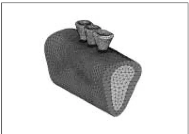
의 두께로 자른 다음, 이를 삼차원 구조 재현을 위한 기초 자료로 이용하였다. 이 절단면을 모눈종이 상에 서 사도(tracing)하고 미리 부여한 좌표 원점을 기준 으로 좌표 값을 산출하고 이를 토대로 하악골의 삼차 원 유한요소 분석의 기초자료를 만들었다.(Fig. 1) 초기 모델링은 workstation 상에서 모델링 전문 프로 그램인 IronCad(Version 5.0, IronCad, Inc., USA) 를 사용하여 표면작업을 하였고, 유한요소 격자 (mesh)는 전문 프로그램인 Nisadisplay(Version 11.0, EMRC, Inc., USA)를 사용하여 구성하였으며 각 요소(element)는 8절점(node)의 삼각뿔 형태인 tetra hedron element로 이루어지도록 하였다.(Fig.
2) 각 모델간 해석의 형평성을 위해서 요소 수는 그 차이가 10,000개 내외가 되게 하였고, 절점 수는 모 든 모델에 대해서 2,000개 내외로 하여 유한요소 분 석에 있어서 요소 수와 절점 수의 차이에 따른 해석 의 오차를 줄였다.(Table I)
선형적 구조해석은 상업용 유한요소 코드인 Nis- adisplay(Version 11.0, EMRC, Inc., USA) 유한요 소 분석 프로그램을 이용하여 workstation상에서 해석하였다.
2. 모델의 분류
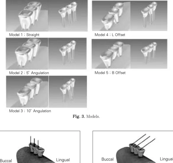
기준모델 1은 고정체를 일직선 수직으로 식립하였 으며, 모델 2와 모델 3은 고정체를 일직선으로 배열 하되, 모델 2는 제1소구치에 해당하는 고정체를 5�
협측으로, 제2소구치에 해당하는 고정체를 5�설측 으로, 제1대구치에 해당하는 고정체를 5�협측으로 기울여 식립하여 각도의 변화를 주었고, 모델 3은 각각 10�로 기울기를 증가 시켰다. 모델 4와 5는 고 정체를 수직으로 식립하되 위치변화를 주기 위해 모 델 4는 제2소구치에 해당되는 고정체를 설측으로 1mm 삼각배치를 하였고(L Offset), 모델 5는 제2소 구치에 해당되는 고정체를 협측으로 1mm 삼각배 치를 하여(B Offset) 총 5개의 모델을 제작하였다.
(Fig. 3) 3. 하중조건
하중은 각 치아의 평균 저작압(소구치 288N, 제1 대구치 565N)으로12-14)협측 교두에 수직하중과 경사 하중(설측에서 협측방향으로 30�)을 가하여 각 구성 부와 지지조직에서 발생하는 응력의 변화와 크기를 계측하였다.(Fig. 4)
4. 물성치와 경계조건
재료의 물성치인 탄성계수(E, Young’s Modulus) 와 프와송비(υ, Poisson’s Ratio)는 선학들의 보고를 참고로 하였다.(Table II)15-19)
Fig. 1. Solid model. Fig. 2. Finite Element Model.
Table I. The number of elements & nodes Model Number of elements Number of nodes
1 100,024 19,234
2 98,424 19,737
3 96,122 18,723
4 91,209 17,912
5 89,819 17,666
모형의 물리적 특성은 균질성(homogeneity), 등방 성(isotropy), 선형탄성(linear elasticity)으로 가정 하였다. 또한 경계조건으로서 모형 절편의 양쪽 모 서리 두 부분에서 Ux, Uy, Uz방향의 자유도(degree of freedom)는 모두 구속하였고, 보철물과 임플랜트 및 주변 골조직에서는 변형을 허용하였다.
Fig. 4. Vertical and oblique force.
Fig. 3. Models.
Table II. Material properties
Young’s modulus Poisson’s
`` (MPa) ratio
Cortical bone 13,700 0.30
Cancellous bone 1,370 0.30
Titanium 102,195 0.35
Composite resin 12,500 0.35
Gold screw 99,300 0.35
``Gold crown 100,000 0.35
Lingual Buccal
Model 1 ; Straight Model 4 ; L Offset
Model 5 ; B Offset Model 2 ; 5。Angulation
Model 3 ; 10。Angulation
Buccal Lingual
5. 응력분석
여러 가지 응력 중 유효응력(Von mises stress)으 로 기준모델과 고정체의 기울기의 변화와 위치변화 에 따라 비교하였다. 전체 응력의 분포상태와 최대 응력 집중부를 식별하기 위하여 응력 등고선식 (stress contour plot)을 이용하였다. 지지골, 고정체, 보철물, 지대주 나사 및 지지골, 고정체, 보철물, 지 대주 나사를 포함하는 전체에서의 유효응력 분포와 최대 유효응력의 크기를 비교하였다.
Ⅲ. 연구성적
기준모델 1과 고정체에 경사를 부여한 모델 2, 3 그리고 고정체의 위치를 변화시킨 모델 4, 5의 유한 요소 모델에서 수직하중과 경사하중을 가한 경우 지 지골과 각 구성부에서 발생한 응력은 다음과 같다.
(Table III)
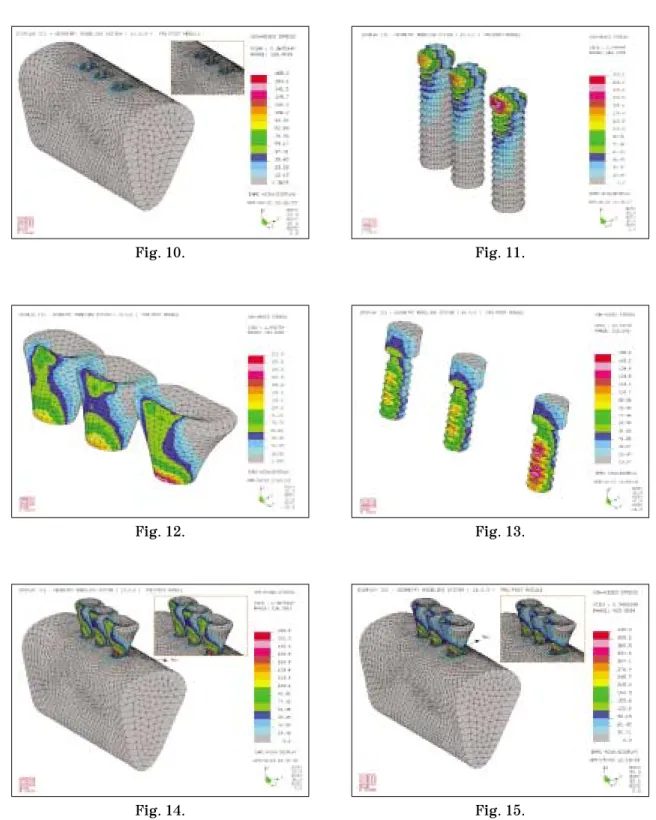
1. 지지골 조직에서의 유효응력(Fig. 5)
1) 협측 교두에 수직하중을 가한 경우
각 모델마다 협측 치조정 부위로 응력이 높게 나타 났으나 그 외 치밀골이나 해면골에서는 0.2�
0.5MPa로 비교적 균등한 응력분포를 나타냈다.
2) 협측 교두에 경사하중을 가한 경우
고정체를 10�의 경사로 식립한 모델에서 최대 유 효응력이 가장 큰 값을 나타냈으며 고정체를 5�의 경사로 식립한 모델에서 최소였다.
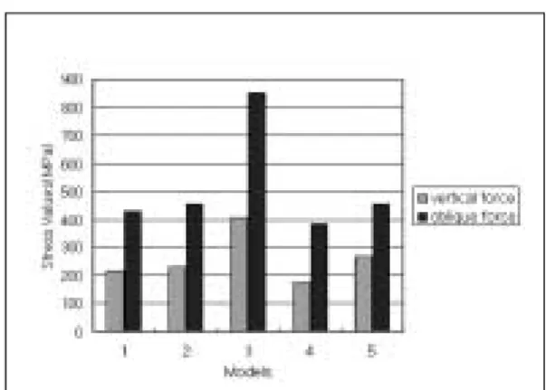
2. 고정체에서의 유효응력(Fig. 6)
1) 수직하중을 가한 경우
최대 유효응력이 고정체를 10�의 경사로 식립한 모델 3에서 가장 크게 나타났으며, 설측 삼각배치한 모델 4에서 가장 적었다. 각 모델마다 보철물/임플랜
Table III. The maximum von mises stress of models
Model 1 Model 2 Model 3 Model 4 Model 5
Vertical Oblique Vertical Oblique Vertical Oblique Vertical Oblique Vertical Oblique
Bone 165 349.6 148.5 299 206.4 435 141.7 322.7 165.6 303.5
Fixture 216.8 430 229.6 455 407.7 849.1 174.5 387.5 264.8 455.6
Superstructure 212.9 394.1 237 379.4 327.2 557.3 320.9 427.9 314.9 403.7 Abutment screw 155.6 332.1 229.6 321.4 157 304 141 292.2 144.5 261.5 Total body 216.8 430 237 455 407.7 849.1 320.9 427.9 314.9 455.6
Fig. 5. The maximum von mises stress of bone. Fig. 6. The maximum von mises stress of fixture.
트의 계면에서 응력이 높게 나타났으며, 특히 제1대 구치에 해당되는 고정체에서 응력이 높게 나타났다.
2) 경사하중을 가한 경우
최대 유효응력은 수직하중을 가한 경우와 유사하 게 고정체를 10�의 경사로 식립한 모델 3에서 최대 였으며, 설측 삼각배치한 모델 4에서 최소였고, 수직 하중을 가했을 경우보다 격차가 컸다.
3. 보철물에서의 유효응력(Fig. 7)
1) 수직하중을 가한 경우
최대 유효응력은 직선으로 식립한 모델 1에서 가 장 작았고, 5개의 전체 모델에서 유효응력은 보철물 의 협측 교두부터 협측 치경부까지 넓게 분포되었으
며 특히 협측 치경부에 응력이 가장 크게 집중되는 경향을 보였다.
2) 경사하중을 가한 경우
최대값은 10�의 경사로 고정체를 식립한 모델 3이 었으며, 최소값은 5�경사로 식립한 모델 2였다.
4. 지대주 나사에서의 유효응력(Fig. 8)
1) 수직하중을 가한 경우
응력분포는 지대주 나사 전체에 넓게 분포되었으 며 특히 제1대구치의 지대주 나사에서 증가되는 경 향을 보였다. 지대주 나사에서 최대 유효응력은 5�
경사로 식립한 모델 2에서 최대였고 설측 삼각배치 시 최소였다.
2) 경사하중을 가한 경우
직선으로 식립한 모델 1에서 최대 유효응력이 최대 였으며, 모델 2, 모델 3, 모델 4, 모델 5의 순으로 감소 되어 최소값은 협측 삼각배치 시 261.5MPa였다.
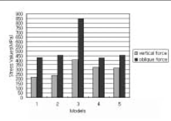
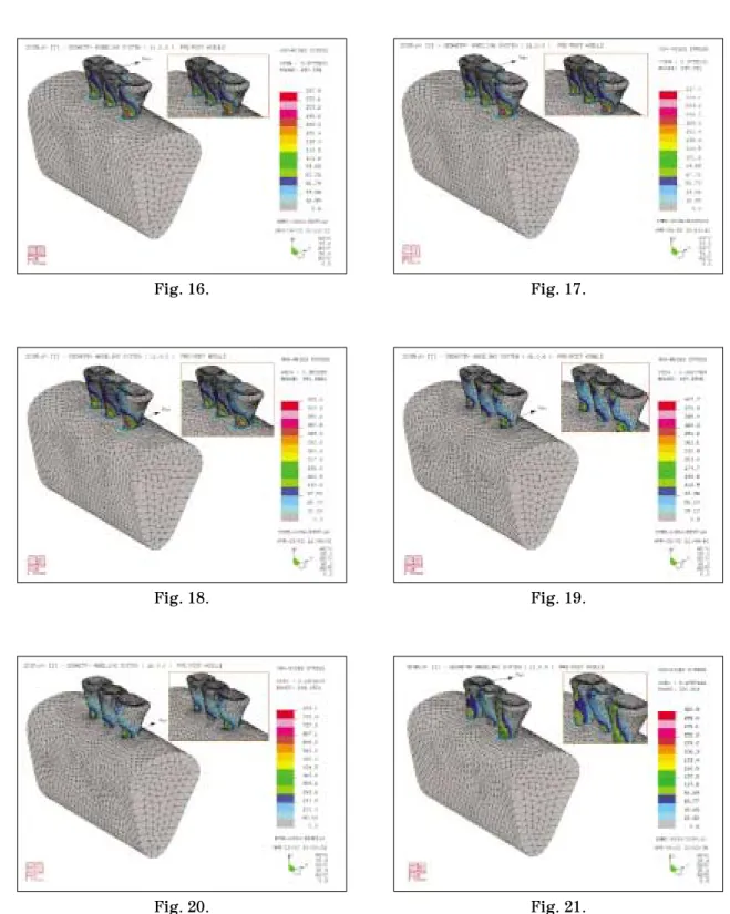
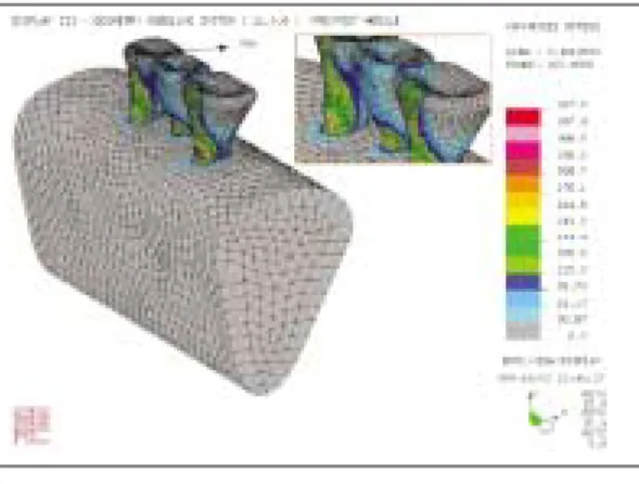
5. 전체에서의 유효응력(Fig. 9)
1) 수직하중을 가한 경우
최대 유효응력이 집중된 곳은 모델 1과 모델 3에 서는 제1대구치 협측 치경부였으며, 모델 2는 제2소 구치 협측 교두였고, 모델 4와 모델 5에서는 제1소 구치 협측 교두였다.
Fig. 8. The maximum von mises stress of abutment screw.
Fig. 7. The maximum von mises stress of super- structure.
Fig. 9. The maximum von mises stress of total body.
2) 경사하중을 가한 경우
최대 유효응력은 모델 3에서 최대였고 모델 4에서 최소였다(427.9MPa). 각 모델에서 최대 유효응력 집중부위는 모델 4에서는 제1소구치 협측 교두였으 며, 그 외 모델에서는 제1대구치 협측 치경부였다.
Ⅳ. 총괄 및 고찰
임플랜트 보철물에서는 가해진 교합하중이 효과적 으로 분산되고 지지조직에 발생되는 응력이 최소화 되어야 한다. 응력에 관한 생역학적 연구는 인체를 실험대상으로 할 수 없는 제약 때문에 미미하였으나 유한요소 해석방법을 이용하면서 이에 대한 연구가 활발해졌다.1-4,20-29)
유한요소법은 구조물의 물리적 성질을 대입한 후 기계적인 이상화를 시킨 뒤 각 요소의 변형과 응력 성분을 구하는 것으로30)모델이 실제와 근접한 해석 을 얻기 위해서는 가능한 많은 요소를 갖도록 설계 되어야 하나, 요소 수가 증가하면 시간의 소요 등 문 제점이 많아 기하학적 형태나 물리적 성질을 지나치 게 단순화시킨 모델을 이용해 왔다.31)
본 연구에서는 해부학적으로 가능한 한 유사한 형 태를 재현하기 위해 요소 수를 100,000개 내외로, 절 점 수를 20,000개 내외의 많은 요소를 갖도록 했으 며, 또한 각 모델간의 해석의 오차를 줄이기 위해 요 소 수와 절점 수를 비슷하게 분할하여 유한요소 모 델을 제작하였다. 그리고 각 모델에서 고정체의 각 도와 위치 이외의 모든 조건은 일치시켜 해석하였 다. 교두 형태는 교두 각을 0�로 단순화 시켰으며 소 구치에 288N, 제1대구치에 565N을 협측교두에 수 직과 경사하중을 가했는데 경사하중은 설측에서 협 측으로 30�경사로 가했다.32-36) 동일한 조건하에서 고정체의 각도와 위치만을 변화시켜 5개의 모델을 제작했는데, 모델 1은 고정체를 일직선 수직으로 식 립하여 기준모델로 했으며 각도를 달리한 모델 2, 3 과 위치를 달리한 모델 4, 5를 각각 기준모델 1과 비 교하였다. 여러 가지 응력 중 유효응력(Von mises stress)을 이용했으며 지지골, 고정체, 보철물, 지대 주 나사, 및 지지골, 고정체, 보철물, 지대주 나사 등 모두를 포함하는 전체에서의 응력분포와 최대 유효 응력을 비교하였다.
각도를 달리한 모델 2, 3을 기준모델 1과 비교하였 을 때 지지골에서의 최대 유효응력은 5�경사로 고정 체를 식립한 모델 2에서는 기준모델 1보다 수직하 중, 경사하중 하에서 모두 감소했고 10�경사로 고정 체를 식립한 모델 3에서는 모두 증가하였다. 최대 유효응력 값이 발생된 부위는 제1대구치 협측골 부 위였다. Kivanc 등20)은 하악 구치부 부분 무치악을 임플랜트로 수복할 경우 고정체의 식립각이 증가될 수록 지지골에 인장력이 증가된다고 했으며, Kredze 등37)은 고정체의 식립각이 증가할수록 피질골에 인 장 응력이 증가했다고 보고하였다. 그러나 본 연구 에서는 고정체를 5�경사로 식립한 경우 수직으로 식립한 경우보다 수직, 경사하중 모두에서 지지골에 서 응력이 오히려 감소하고 10�경사로 고정체를 식 립한 경우 증가함을 보였다.
고정체에서는 수직하중과 경사하중 하에서 모델 2 와 3은 모델 1에 비해 최대 유효응력이 모두 증가했 고 특히 모델 3에서 크게 증가했다. 모델 1, 2, 3에서 최대 유효응력은 제1대구치 부위의 고정체의 머리부 분이었다. 이는 고정체의 식립각을 증가시킬수록 고 정체에 응력이 집중되므로 고정체를 경사지게 식립 할 경우 직경이 큰 고정체를 식립하는 것이 바람직 하다고 할 수 있다.
보철물에서는 수직하중 하에서의 최대 유효응력은 모델 2와 3에서 모델 1에 비해 증가했으나 경사하중 하에서는 모델 2에서는 감소했으나 모델 3에서는 크 게 증가했다. 이는 모델 2에서의 최대 유효응력이 보철물이 아닌 제1대구치 부위의 고정체의 머리부분 에 발생되었기 때문이라고 사료된다. 최대 유효응력 이 발생된 부위는 수직하중 조건하에 모델 2에서만 제2소구치 협측 교두였고 그 외는 제1대구치 치경부 부위였다. 고정체에 경사를 부여할 경우 보철물에 응력이 집중되므로 보철물의 파절을 예방하는 재료 의 선택이 중요하다고 할 수 있다.
지대주 나사 부분에서는 수직하중 시 모델 2에서 는 모델 1에 비해 최대 유효응력이 크게 증가되었으 나 모델 3에서는 변화가 없었다. 경사하중 시 모델 2 와 3에서는 감소되었다. 이는 응력이 나사에서 다른 부위로 이동하는 것으로 사료된다. 최대 유효응력이 발생된 부위는 모델 1, 2, 3 모두에서 제1대구치에 해당되는 지대주 나사의 하부였다.
전체적으로 볼 때 수직하중과 경사하중 하에서 모 델 2에서는 모델 1에 비해 최대 유효응력이 10%이 내로 증가되었으나 모델 3에서는 50%이상의 증가를 보였다. 최대 유효응력이 발생된 부위는 경사하중 시 모델 2의 제2소구치 협측 교두였고 그 외의 조건 하에서는 모두 제1대구치에 해당하는 고정체의 치경 부였다. 이는 고정체의 식립각이 증가할수록 치조골 과 임플랜트 치경부에 응력이 집중되는 현상으로 고 정체를 근심으로 10�, 15�, 20�로 경사시킨 경우 근 심 경사각이 커질수록 피질골에 발생하는 응력의 양 이 증가되었다는 이 등38)의 보고와 일치한다.
고정체를 경사시켜 식립하고 수직하중과 경사하중 을 가했을 때 지지골에서는 5�경사 시 응력이 감소 하고 10�경사 시 응력이 증가함을 보였다. 또한 고정 체에서는 응력이 증가했으나 경사각이 증가할수록 크게 증가함을 보였다. 보철물에서는 응력이 증가했 으나 일률적인 양상을 보이지는 않았고 지대주 나사 에서는 수직하중 하에서 5�의 경사에서만 응력이 증 가했고 경사하중 시에는 감소하는 경향을 보였다.
지지골을 포함하는 전체에서는 수직하중과 경사하 중 모두에서 고정체의 식립각이 5�인 경우 최대 유 효응력이 10%이내로 증가되었으나 10�에서는 50%
이상의 증가를 보였다
한편 고정체의 위치를 달리한 모델 4, 5를 기준모 델 1과 비교하였을 때 지지골에서는 수직하중을 가 했을 경우 고정체를 설측 삼각배치한 모델 4에서는 모델 1에 비해 최대 유효응력이 감소했고 협측 삼각 배치한 모델 5에서는 거의 변화가 없었다. 경사하중 을 가한 경우 모델 4와 모델 5에서 모두 감소했다.
따라서 삼각배치가 일직선 배치보다 지지골에서의 응력 발생을 감소시켰으며 제1대구치 협측골 부위에 최대 유효응력이 집중했다. 이는 지지골의 질과 양 이 불리할 경우 고정체를 삼각배치 하는 것이 유리 하다 할 수 있다.
고정체인 경우 수직하중과 경사하중을 가했을 경 우 모델 4에서는 모델 1에 비해 최대 유효응력이 감 소되었고 협측 삼각배치한 모델 5에서는 증가되었 다. 이는 하악 구치부 무치악에 있어서 임플랜트로 수복할 경우 고정체에서 발생하는 응력을 감소시키 기 위해서는 설측 삼각배치가 유리하다고 할 수 있 다. 최대 유효응력은 모두 제1대구치에 해당하는 고
정체의 머리 부분에 집중되므로 직경이 큰 고정체를 식립하는 것이 추천된다.
보철물에서는 수직하중과 경사하중 모두에서 최대 유효응력이 일직선 배치보다 삼각배치에서 증가되 었고 제1소구치의 협측 교두와 제1대구치 치경부에 최대 유효응력이 집중되었다. 따라서 수복할 보철물 의 적절한 재료의 선택이 중요하다 할 수 있다.
지대주 나사의 경우 수직하중과 경사하중 모두에 서 모델 4와 모델 5에서 최대 유효응력이 감소되었 다. 이는 삼각배치를 하는 경우 응력이 보철물에서 는 증가되고 지대주 나사에서는 감소되므로 지대주 나사를 보호하기에는 삼각배치가 유리하다 할 수 있 다. 최대 유효응력은 제1대구치 지대주 나사의 하부 에 집중되었다. 임플랜트 지지 보철물에서 빈번히 발생되는 합병증은 지대주 나사의 풀림과 파절, 그 리고 지지골의 흡수 등이며39-43)또한 임플랜트 보철 물에 과도한 측방력이 가해지면 지대주 나사의 풀림 이나 파절이 발생하게 된다.44) Andersson 등45)은 Bra°nemark system에서 가장 취약한 부분이 지대주 나사였다고 보고했고, Jemt 등46)과 Becker 등47)은 40%이상의 높은 나사 풀림 현상이 지대주 연결부에 서 발견되었음을 보고하였고, Beat 등48)은 장축 방향 의 압축력을 제외하고 모든 외부적 힘 요소들이 지 대주 나사에 집중되기 때문에 고정체에 외측 육각 구조를 가지는 임플랜트들은 나사 풀림 경향이 있다 고 보고하였다.
한편 임플랜트 지지 보철물에서는 수직력 보다는 측방력이 가해졌을 때 지지 조직과 보철물에 응력이 증가되기 때문에 측방력이 많이 발생하는 경사 하중 조건 하에서는 응력이 감소되도록 고정체를 위치시 키는 것이 중요하다.49) 따라서 본 연구의 지대주 나 사 부분에서 경사하중 시 발생하는 응력의 결과에 따르면 Bra°nemark system같은 외측 육각 구조를 가 지는 고정체를 식립 시 일직선 수직으로 식립하는 것보다 삼각배치로 수직으로 식립하는 것이 지대주 나사에 응력집중을 피할 수 있어 파절로 인한 실패 를 줄일 수 있다.
전체적으로 볼 때 수직하중 하에서는 모델 4와 모 델 5는 모델 1에 비해 최대 유효응력이 증가했으며 경사하중을 가했을 경우에는 모델 4에서는 모델 1에 비해 감소했고 모델 5에서는 증가했다. 최대 유효응
력이 나타난 부위는 수직 하중 하에서는 설측 삼각 배치와 협측 삼각배치 시 그리고 경사 하중조건 하 에서 설측 삼각배치 시 제1소구치 협측 교두였으며 그 외에는 제1대구치 치경부 부위였다.
Rangert 등49)은 임플랜트에 가해지는 하중은 식립 위치에 따라 변화되며, 고정체를 직선으로 식립하면 측방력이 가해졌을 때 임플랜트가 휘는 힘을 받기 때문에 고정체를 협설로 2�3mm 삼각배치를 하면 20�60%의 응력을 감소시킬 수 있다고 하였다. 그 러나 Rangert 등49)의 연구에서는 삼각배치가 직선배 치보다 응력이 감소된다는 결과만을 보고했다. 그리 고 Kruger 등50-51)은 상악에서는 협측 삼각배치가 그 리고 하악에서는 설측 삼각배치가 고정체와 지대주 나사의 응력을 감소시킨다고 했는데 이는 이차원 평 면에서 힘의 벡타 계산에 근거하여 결과를 도출해 냈으며 세 개의 임플랜트를 계산한 것이 아니라 삼 각배치로 일직선에서 벗어난 임플랜트에 대해서만 계산한 결과이다.
이번 연구의 한계점으로는 Bra°nemark system을 사용하여 고정체의 식립 위치와 각도에 따른 응력분 산의 결과이므로 다른 시스템에서도 일률적으로 적 용시킬 수 없다고 사료된다. 그리고 하악 구치부에 국한시켜 모델링 했으며 환자마다 교합 관계와 악골 형태가 다양하므로 일률적으로 본 연구결과를 적용 시키기에는 문제점이 있을 수 있다.
이에 삼차원 유한요소법을 이용하여 임플랜트 지 지 보철물에서 고정체의 위치와 식립 각도에 따라 응력 분산의 양상을 비교한 결과 다음과 같은 결과 를 얻었다.
Ⅴ. 결 론
본 연구는 하악 부분 무치악 임플랜트 지지 보철물 에서 고정체의 각도와 위치에 따른 응력의 분포를 3 차원 유한요소법을 이용하여 비교해 다음과 같은 결 론을 얻었다.
1. 하악 구치부 부분 결손을 수복하는 임플랜트 지 지 보철물에서 고정체에 각도를 부여함은 응력분 산에 도움을 주지 못했다.
2. 고정체를 기울여 식립할 경우 임플랜트 주위 지 지골에서 응력이 증가하므로 고정체를 수직으로
식립하는 것이 응력감소에 유리했다.
3. 고정체를 기울여 식립할 경우 보철물에 응력이 집중되므로 보철물의 파절을 방지할 수 있는 재 료의 선택이 중요하다.
4. 하악 구치부 부분 결손을 임플랜트 지지 보철물 로 수복할 경우 고정체의 삼각배치가 응력분산에 효과적이었다.
참고문헌
1. Weinberg LA, Kruger B. Biomechanical considerations when combining tooth-supported and implant-supported prostheses. Oral Surg Oral Med Oral Pathol 1994;78:22- 27.
2. Bergman B. Evaluation of results of treatment with osseointegrated implants by the Swedish National Board of Health and Welfare. J Prosthet Dent 1983;50:114-120.
3. Bra°nemark PI. Osseointegration and its experimental background. J Prosthet Dent 1983;50:399-410.
4. Robert AJ, Charles LB. The excessive loss of bra°nemark fixtures in type Ⅳ bone: A 5-year analysis. J Periodontol 1991;62:2-4.
5. David MD. The role of implants in the treat- ment of edentulous patients. Int J Prosthodont 1990;3:42-49.
6. David CH, William RG, Vijay KG. Comp- arison of stress transmission in the IMZ implant system with polyoxymethylene or tita- nium intramobile element - A finite ele- ment stress analysis. Int J Oral Maxillofac Implants 1992;7:450-458.
7. Davis DM, Zarb GA, Chao YL. Studies on frameworks for osseointegrated prostheses.
Part 1. The effect of varying the number of supporting abutments. Int J Oral Maxillofac Implants 1988;3:197-201.
8. Ferrario V, Sforza C. Biomechanical module of the human mandible - A hypothesis
involving stabilizing activity of the superior belly of lateral pterygoid muscle. J Prosthet Dent 1992;68:829-835.
9. Haldun I, Kivanc A. Comparative evaluation of the effect of diameter, length and number of implants supporting three-unit fixed par- tial prostheses on stress distribution in the bone. J Dent 2002;30:41-46.
10. Abani KP, Jason MD, Karl S, et al. Guidelines for analysis and redesign of dental implants.
Implant Dent 1998;7:355-366.
11. Borchers L, Reichart P. Three-dimensional distribution around a dental implant at dif- ferent stages of interface development. J Dent Res 1983;62:25-29.
12. Robert G. Restorative dental materials, 9th ed: Mosby, 1993:54.
13. Philips RW. Skinner’s science of dental materials, 8th ed: WB Saunders, 1982:55.
14. Kenneth J. Phillips’science of dental mate- rials, 10th ed: WB Saunders, 1996:66.
15. Cook SD, Weinstein AM, Klavitter JJ. A three-dimensional finite element analysis of a porous rooted Co-Cr-Mo alloy dental implant. J Dent Res 1994;61:25-29.
16. Katona TR, Winkler MM. Stress analysis of bulk-filled C1V light-cured composite restoration. J Dent Res 1994;73:1470-1477.
17. Ko HJ, Chung CH. Finite element analysis of stresses induced by osseointegrated pros- thesis with or without connection between nat- ural tooth and osseointegrated abutments. J Korean Acad Prosthodont 1991;29:147-160.
18. Kim DW, Kim YS. A study on the osseoin- tegrated prosthesis using three dimensional finite element method. J Korean Acad Prosthodont 1991;29:167-213.
19. Cho HW, Kwon JH. Three-dimensional finite element stress analysis of single implant prosthesis using different fixture and abut- ment screw diameters. J Wonkwang Dent
Res In 2001;10:1-24.
20. Kivanc A, Haldun L. Evaluation of the effect of the residual bone angulation on implant- supported fixed prosthesis in mandibular posterior edentulism part Ⅱ: 3-D finite ele- ment stress analysis. Implant Dent 2001;
10:238-244.
21. Giulio M, Massimo L, Paolo P. Mandibular implant-retained overdenture: Finite ele- ment analysis of two anchorage systems.
Int J Oral Maxillofac Implants 1998;13:369- 376.
22. Atilla S. Finite element analysis study of the effect of superstructure material on stress distribution in an implant-supported fixed prosthesis. Int J Prosthodont 1997;10:19-27.
23. George P, Phophi K, Stephen CB, David AF. Three-dimensional finite element analy- sis of stress-distribution around single tooth implants as a function of bony support, prosthesis type, and loading during function.
J Prosthet Dent 1996;76:633-640.
24. Atilla S, Sungur G. Finite element analysis of the effect of cantilever and implant length on stress distribution in an implant-supported fixed prosthesis. J Prosthet Dent 1996;76:
165-169.
25. Thomas B, Matty FA, Frank P. The exper- imental verification of the efficacy of finite ele- ment modeling to dental implant systems. J Oral Implantol 1996;22:104-110.
26. Clelland NL, Ismail YH, Zaki HS. Three- dimensional finite element stress analysis in and around the screw-vent implant. Int J Oral Maxillofac Implants 1991;6:391-398.
27. Jaime LL, Matty FA, Frank AP. Comparative three-dimensional analysis of two finite- element endosseous implant designs. J Oral Implantol 1994;20:315-321.
28. Meijer HJA, Starmans FJM, Steen WHA, Bosman F. A three-dimensional, finite-ele-
ment analysis of bone around dental impl- ants in an edentulous human mandible.
Arch oral Biol 1993; 38:491-496.
29. Rieger MR, Mayberry M, Brose MO. Finite element analysis of six endosseous implants.
J Prosthet Dent 1990;63:671-676.
30. Lee YS, Yoo KH. Three dimensional finite element analysis of mandibular stresses of complete denture occlusion. J Korean Acad Prosthodont 1992;30:286-318.
31. Heo H, Kang DW. Three-dimensional finite element stress analysis of the jaws at the simulated bilateral and unilateral clenchings.
J Korean Acad Prosthodont 1999; 37:71-92.
32. Thomas RM, Peter AP. Measurement of masticatory forces and implant loads: A methodologic clinical study. Int J Prosthodont 2002;15:20-27.
33. Rees JS. The effect of variation in occlusal loading on the development of abfraction lesions: A finite element study. J Oral Rehabil 2002;29:188-193.
34. Meijer HJA, Starmans FJM, Steen WHA, Bosman F. Loading conditions of endosseous implants in an edentulous human mandible:
a three-dimensional, finite-element study.
J Oral Rehabil 1996;23:757-763.
35. Hanne F, Lars L, Dan L. Occlusal force pattern in dentitions with mandibular implant-supported fixed cantilever prosthe- ses occluded with complete dentures. Int J Oral Maxillofac Implants 1989;4:55-62.
36. Dan L, Lars L, Hanne F. Occlusal force pattern during mastication in dentitions with mandibular fixed partial dentures sup- ported on osseointegrated implants. J Prosthet Dent 1987;58:197-203.
37. Kregzde M. A method of selecting the best implant prosthesis design option using three- demensional finite element analysis. Int J Oral Maxillofac implants 1993;8:662-673.
38. Lee JH, Kim CW, Kim YS. A comparison of load transfer in screw-and cement-retained implant fixed partial denture designs. J Korean Acad Prosthodont 2001;39:125-145.
39. Boggan RS, Strong MJ, Misch CE. Influence of hex geometry and prosthetic table width on static and fatigue strength of dental implants. J Prosthet Dent 1999;82: 436-440.
40. Seghi RR, Denry IL, Rosenstiel SF. Relative fracture toughness and hardness of new dental ceramics. J Prosthet Dent 1995;74:
145-150.
41. Hertel RC, Kalk W.: Influence of the dimen- sions of implant superstructure on peri- implant bone loss. Int J Prosthodont. 1993;
6:18-24.
42. Hans VO, Joke D, Jos VS, The influence of bone mechanical properties and implant fix- ation upon bone loading around oral implants.
Clin Oral Impl Res 1998;9:407-418.
43. Lazzara RJ. Criteria for implant selection:
Surgical and prosthetic considerations. The Implant Report 1994;6:55-62.
44. Sato Y, Shindoi N, Hosokawa R, Tsuga K, Akagawa Y. A biomechanical effect of wide implant placement and offset placement of three implants in the posterior partially edentulous region. J Oral Rehabil 2000;27:15-21.
45. Andersson B, Boss A, Jorneus L. Mechanical testing of superstructures on the Ceraone abut- ment in the Bra°nemark system. Int J Oral Maxillofac Implants 1994;9:665-672.
46. Jemt T, Laney WR, Harris D. Osseointegrated implants for single tooth replacement: A 1 year report from a multicenter prospective study.
Int J Oral Maxillofac Implants 1991;6:29-36.
47. Becker W, Becker BE. Replacement of max- illary and mandibular molars with single endosseous implant restorations: A retrospective study. J Prosthet Dent 1995;74:51-55.
48. Beat RM, Stephan H, Urs CB. Mechanics of
the implant-abutment connection: An 8- Degree Taper Compared to a butt joint con- nection. Int J Oral Maxillofac Implants 2000;15:519-526.
49. Rangert BR, Sullivan RM, Jemt TM.: Load factor control for implants in the posterior partially edentulous segment. Int J Oral Maxillofac Implants. 1997;12:360-370.
50. Weinberg LA, Kruger B. An Evaluation of torque (moment) on implant/prosthesis with staggered buccal and lingual offset. Int J Periodont Rest Dent 1996;16:253-265.
51. Weinberg LA. The biomechanics of force distribution in implant-supported prostheses.
Int J Oral Maxillofac Implants 1993;8:19-31.
Reprint request to:
Won-Hee Park, D.D.S., M.S., Ph.D.
Department of Dentistry, College of Medicine, Hanyang University 17, Hangdang-Dong, Sungdong-Gu, Seoul, 133-792, Korea [email protected]
Explanations of Figures
Fig. 10. The bone area of non-inclined & straight implantation model 1 that the vertical force was applied on the buccal cusps
Fig. 11. The fixtures of non-inclined & straight implantation model 1 that the vertical force was applied on the buccal cusps
Fig. 12. The superstructure of non-inclined & straight implantation model 1 that the vertical force was applied on the buccal cusps
Fig. 13. The abutment screws of non-inclined & straight implantation model 1 that the vertical force was applied on the buccal cusps
Fig. 14. The total area of non-inclined & straight implantation model 1 that the vertical force was applied on the buccal cusps
Fig. 15. The total area of non-inclined & straight implantation model 1 that the oblique force was applied on the buccal cusps
Fig. 16. The total area of 5�-inclined & straight implantation model 2 that the vertical force was applied on the buccal cusps
Fig. 17. The total area of 5�-inclined & straight implantation model 2 that the oblique force was applied on the buccal cusps
Fig. 18. The total area of 10�-inclined & straight implantation model 3 that the vertical force was applied on the buccal cusps
Fig. 19. The total area of 10�-inclined & straight implantation model 3 that the oblique force was applied on the buccal cusps
Fig. 20. The total area of 10�-inclined & straight implantation model 3 that the oblique force was applied on the buccal cusps
Fig. 21. The total area of non-inclined & lingual offset implantation model 4 that the vertical force was applied on the buccal cusps
Fig. 22. The total area of non-inclined & lingual offset implantation model 4 that the oblique force was applied on the buccal cusps
Fig. 23. The total area of non-inclined & buccal offset implantation model 5 that the vertical force was applied on the buccal cusps
Fig. 24. The total area of non-inclined & buccal offset implantation model 5 that the oblique force was applied on the buccal cusps
Figures ①
Fig. 10. Fig. 11.
Fig. 12. Fig. 13.
Fig. 14. Fig. 15.
Figures ②
Fig. 16. Fig. 17.
Fig. 18. Fig. 19.
Fig. 20. Fig. 21.
Figures ③
Fig. 22. Fig. 23.
Fig. 24.
Statement of problem. The implant prosthesis has been utilized in various clinical cases thanks to its increase in scientific effective application. The relevant implant therapy should have the high success rate in osseointegration, and the implant prosthesis should last for a long period of time without failure. Resorption of the peri-implant alveolar bone is the most frequent and serious prob- lem in implant prosthesis. Excessive concentration of stress from the occlusal force and biopressure around the implant has been known to be the main cause of the bone destruction. Therefore, to decide the location and angulation of the implant is one of the major considering factors for the stress around the implant fixture to be dispersed in the limit of bio-capacity of load support for the successful and long-lasting clinical result. Yet, the detailed mechanism of this phenomenon is not well understood. To some extent, this is related to the paucity of basic science research.
Purpose. The purpose of this study is to perform the stress analysis of the implant prosthe- sis in the partially edentulous mandible according to the different fixture locations and angula- tions using three dimensional finite element method.
Material and methods. Three 3.75mm standard implants were placed in the area of first and second bicuspids, and first molar in the mandible. Thereafter, implant prostheses were fabricated using UCLA abutments.
Five experimental groups were designed as follows: 1) straight placement of three implants, 2) 5�buccal and lingual angulation of straightly aligned three implants, 3) 10�buccal and lingual angulation of straightly aligned three implants, 4) lingual offset placement of three implants, and 5) buccal offset placement of three implants. Average occlusal force with a variation of perpen- dicular and 30�angulation was applied on the buccal cusp of each implant prosthesis, followed by the measurement of alteration and amount of stress on each configurational implant part and peri-implant bio-structures.
THREE DIMENSIONAL FINITE ELEMENT STRESS ANALYSIS OF IMPLANT PROSTHESIS ACCORDING TO THE DIFFERENT
FIXTURE LOCATIONS AND ANGULATIONS
Won-Hee Park, D.D.S., M.S., Ph.D., Young-Soo Lee, D.D.S., M.S., Ph.D.
Department of Dentistry, College of Medicine, Hanyang University ABSTRACT
The results of this study are extracted from the comparison between the distribution of Von mis- es stress and the maximum Von mises stress using three dimensional finite element stress analy- sis for each experimental group.
Conclusion. The conclusions were as follows:
1. Providing angulations of the fixture did not help in stress dispersion in the restoration of par- tially edentulous mandible.
2. It is beneficial to place the fixture in a straight vertical direction, since bio-pressure in the peri-implant bone increases when the fixture is implanted in an angle.
3. It is important to select an appropriate prosthodontic material that prevents fractures, since the bio-pressure is concentrated on the prosthodontic structures when the fixture is implanted in an angle.
4. Offset placement of the fixtures is effective in stress dispersion in the restoration of partially edentulous mandible.
Key words : Three dimensional finite element stress analysis, Implant prosthesis, Alveolar bone, Von mises stress, Offset placement