• 검색 결과가 없습니다.

Performance Test and Evaluations of a MEMS Microphone for the Hearing Impaired

N/A
N/A
Protected

Academic year: 2021

Share "Performance Test and Evaluations of a MEMS Microphone for the Hearing Impaired"

Copied!
6
0
0

로드 중.... (전체 텍스트 보기)

전체 글

(1)

Abstract

In this study, a MEMS microphone that uses Si

3

N

4

as the vibration membrane was produced for application as an auditory device using a sound visualization technique (sound visualization) for the hearing impaired. Two sheets of 6-inch silicon wafer were each fabricated into a vibration membrane and back plate, after which, wafer bonding was performed. A certain amount of charge was created between the bonded vibration membrane and the back plate electrodes, and a MEMS microphone that functioned through the capacitive method that uses change in such charge was fabricated. In order to evaluate the characteristics of the prepared MEMS microphone, the frequency flatness, frequency response, properties of phase between samples, and directivity according to the direction of sound source were analyzed. The MEMS microphone showed excellent flatness per fre- quency in the audio frequency (100 Hz–10 kHz) and a high response of at least −42 dB (sound pressure level). Further, a stable differential phase between the samples of within −3 dB was observed between 100 Hz–6 kHz. In particular, excellent omni- directional properties were demonstrated in the frequency range of 125 Hz–4 kHz.

Keywords: MEMS, Microphone, Phase, Directionality

1. INTRODUCTION

Recently, the demand for multifunctionality, high-functionality, size reduction, and thickness reduction of mobile devices has become an important factor in determining the value of a product.

Among the technologies available for realizing such demands, the microelectromechanical systems (MEMS) technique, which reduces the sizes of the components, is receiving attention [1].

MEMS technology is based on the fine machining techniques of semiconductors and has high reliability because it makes it possible to machine actuators, sensors, and other components with high accuracy, integrate them with the integrated circuits, and use materials such as crystal silicon [2-4].

For small-sized microphones, the current technology is mainly electret condenser microphones (ECMs) [5,6]. The ECM structure consists of a vibration membrane and fixed electrode forming a

capacitor. Because the ECM uses the electret device, there is no need for an external voltage supply. However, the electret device has poor heat resistance and low response to acoustic pressure.

The temperature in which stable response and frequency properties are realized is between -20

o

C and 80

o

C.

The recently developed MEMS microphone uses MEMS technology; thus, there is no need for electrets, and the smallest sensor chip in the world is used [7-10]. This MEMS microphone has excellent heat resistance, and when mounted, stability can be improved and cost can be reduced. In this study, the microphone prepared through the MEMS design and production process was integrated on a circuit board together with a complementary metal oxide semiconductor (CMOS) signal amplifier, after which the device was completed through the packaging process. Then, the mechanical properties and electrical response characteristics were measured and directive properties evaluated for the completed device.

2. EXPERIMENT AND RESULTS

2.1 Design of the MEMS Microphone

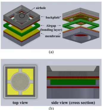
The capacitive-type MEMS microphone is composed of a vibration membrane electrode and a back plate electrode that maintain a certain distance in between [11-13]. As shown in Fig. 1, if the

1

Korea Institute of Machinery & Materials, 156 Gajeongbuk-Ro, Yuseong-gu, Daejeon, 305-343, Korea.

2

School of Electronics Engineering, Kyungpook National University, Daehakro, Bukgu, Daegu, 702-701, Korea.

+

Corresponding author: [email protected]

(Received : Jun. 16, 2014, Revised : Aug. 22, 2014, Accepted : Aug. 22, 2014)

This is an Open Access article distributed under the terms of the Creative Commons Attribution Non-Commercial License(http://creativecommons.org/

licenses/bync/3.0) which permits unrestricted non-commercial use, distribution,

and reproduction in any medium, provided the original work is properly cited.

(2)

capacitance between the two electrodes with constant inter-electrode distance is referred to as C

1,

and the capacitance when altering the inter-electrode distance is referred to as C

2

, the capacitance value C

diff

of the MEMS microphone can be expressed as the difference between C

1

and C

2

. Equation 1 shows the capacitance value C

diff

of the MEMS microphone according to the definition of parallel-plate capacitance.

(1)

Because C

diff

has a significant effect on the response of the MEMS microphone, this study proposes a structure that allows for natural air inflow and the generation of high response movement of the vibration membrane. Fig. 2 shows the schematic diagram of the MEMS microphone. The size of the actual MEMS microphone produced is 4 * 4 * 1 mm

3

.

2.2 Fabrication of the MEMS Microphone

The membrane that is used as the vibration membrane electrode and the back plate that has an acoustic hole were each fabricated on the wafer. The device was completed through a bonding process at the wafer scale. First, the vibration membrane was formed on the 6-inch silicon wafer through the Low Pressure Chemical Vapor Deposition (LPCVD) technique, after which gold was deposited to be used as an electrode. Next, Deep Reactive Ion Etching (DRIE) was performed on its back side to fabricate the membrane. For the fabrication of the back plate, an etching process with KOH was performed to adjust the 6-inch silicon wafer thickness to approximately 300 µm, after which the air hole was formed for the release of acoustic pressure through the DRIE etching technique on the front side in addition to the deposition of the electrode. After depositing the solder metal (Au/Sn) on the fabricated membrane and the back plate, a eutectic bonding C

diff

ε A

d

1

--- ε A

d

2

--- –

=

Fig. 1. Parallel plate capacitor.

Fig. 2. Schematic of the MEMS microphone. (a) Structure of the MEMS microphone and (b) schematics of the top view and side view.

Fig. 3. Fabrication process of the MEMS microphone.

(3)

process was carried out to complete the MEMS microphone. Fig.

3 shows the fabrication process flow diagram and Fig. 4 shows the actual image of the MEMS microphone.

2.3 Characteristics of the MEMS Microphone

2.3.1 Electromechanical characteristics of the MEMS microphone

Electrical properties were tested according to the behavior of the vibration membrane in order to understand the properties of the fabricated MEMS microphone [14,15]. The applied voltage test for the MEMS microphone was conducted by measuring the displacement of the vibration membrane according to the absolute value of the voltage when an AC voltage was applied to both the vibration membrane electrode and the back plate electrode. The displacement of the vibration membrane was measured through the Laser Doppler Vibrometer (LDV), and the size of the displacement of the vibration membrane due to the AC voltage was measured using the Fast Fourier Transform (FFT) method through an oscilloscope. For the MEMS microphone device, it was observed that the vibration displacement abruptly increased as the magnitude of the AC voltage that was applied on both ends of the electrode increased. Further, it was evident that the measured displacement of the vibration membrane changed at certain voltages depending on the size of the vibration membrane or the face-to-face area of the electrodes. By fabricating MEMS microphone devices with various design parameters and measuring and analyzing their electrical properties, the bias voltage considering the actual process design parameters was confirmed. This experiment also confirmed the design values for the MEMS microphone that could use a bias voltage of 18 V or less, which could be applied through the charge pump of the CMOS signal processing chip that worked with a voltage of approximately 3 V.

Table 1 shows the relationship between the diameter of the vibration membrane and the pull-in voltage according to the air gap as measured through the applied voltage test.

2.3.2 Measurement of frequency response and phase Microphones can have various applications depending on their responsiveness and directivity. To measure the responsiveness and directivity of the MEMS microphone, a microphone testing device (B&K) and reference microphone (Knowles SPM3410) were used [16-18]. The tester generated and collected the frequency signal simultaneously. The tester was used to measure the frequency characteristics in the range of 100 Hz–10 kHz. Figs. 5(a) and 5(b) each show the schematic diagram and the actual measuring system for the assessment of the properties at each frequency.

In an anechoic room, the MEMS microphone and reference microphone were placed in the same location and a speaker that generated sound was placed at a certain distance away from the microphones. The signal input was transferred to a computer through the microphone testing device, after which the LabView software (National Instrument Co. Ltd. USA) and Matlab software were used to analyze the signal. The response of the microphone can be expressed as a voltage (mV) for 1 Pa of acoustic pressure. Here, the obtained value was expressed by converting it to a dB value, as shown in Equation 2. Here, the Output

ref

defined 1 V/Pa (1000 mv/Pa).

(2)

The graph in Fig. 6 shows the sensitivity of the MEMS Sensitivity

dBV

20 Sensitivity

mV Pa

Output

REF

---

⎝ ⎠

⎛ ⎞

log

20

×

= Fig. 4. Fabricated prototype of the MEMS microphone.

1500 10 / 1.0 513 308

5.0 / 1.0 136 81.4

2.0 / 1.0 41.3 24.8

1.5 / 0.5 18.1 10.8

1000 10 / 1.0 985 591

5.0 / 1.0 195 117

2.0 / 1.0 76.3 45.8

1.5 / 0.5 25.9 15.5

(4)

microphone. In the frequency range of 100 Hz–10 kHz, flatness and sensitivity of approximately -42 dB were observed.

In addition, the differential phase was studied by installing at least two microphones in the same line as the speaker to measure the phase characteristics between the MEMS microphones. As shown in Fig. 7(b), the differential phase between the MEMS microphones showed an even response of within 3 dB until 6 kHz.

2.3.3 Measurement of directionality

A rotation holder that can rotate 360° was prepared to measure

the directivity. The MEMS microphone was installed on the rotation holder, and the response properties were measured according to each angle of rotation. The speaker produced a Fig. 5. Measurement system for the MEMS microphone. (a) Sche-

matic of the measurement system for frequency response and (b) image of measurement system.

Fig. 6. Frequency response of the MEMS microphones.

Fig. 7. Phase response of the MEMS microphones. (a) Measurement system of phase response and (b) graph of the result for the characteristic of phase.

Fig. 8. Directionality measurement system. (a) Schematic of the

directionality measurement system and (b) image of setup.

(5)

sinusoidal wave of 1 kHz with an acoustic pressure of 1 Pa.

During the measurement, the angle of the rotation holder was varied in intervals of 30°. Figs. 8(a) and 8(b) show the directionality measurement system.

As shown in Fig. 9, excellent omnidirectional properties were observed in the frequency range of 125 Hz–4 kHz. This signifies that the MEMS microphone can accurately distinguish the sound desired by the user from the surrounding noise.

and the response properties for the sound signal were evaluated.

Further, the system for measuring the directionality according to the sound direction was set up, and such directionality properties were studied. The study results showed excellent omnidirectional properties between 125 Hz–4 kHz. In consideration of the frequencies of sounds from daily life and alarm sounds that are important to the hearing impaired, it is expected that the MEMS microphone would be appropriate for use as a hearing aid.

ACKNOWLEDGMENT

This research was supported by the Pioneer Research Center Program through the National Research Foundation of Korea funded by the Ministry of Science, ICT & Future Planning (2009- 0082960) and was supported by the Development Program of Manufacturing Technology for Flexible Electronics with High Performance (SC1020) funded by Korea Institute of Machinery and Materials (KIMM).

REFERENCES

[1] E. H. Yang and D. V. Wiberg, “A new wafer-level mem- brane transfer technique for MEMS deformable mirrors”, IEEE Conf. on Micro Electro Mechanical Systems, pp. 80- 83, Interlaken, Switzerland, 2001.

[2] O. Auciello, J. Birrell, J. A. Carlisle, J. E. Gerbi, X. Xiao, B. Peng, and H. D. Espinosa, “Materials science and fab- rication processes for a new MEMS technology based on ultra nano crystalline diamond thin films”, J. Phys.-Con- dens. Matter, Vol. 16, No. 16, pp. 532-559, 2004.

[3] F. Jiang, Y. C. Tai, K. Walsh, T. Tsao, G. B. Lee, and C. M.

Ho, “A flexible MEMS technology and its first application to shear stress sensor skin”, Proc. of IEEE workshop. on Micro Electro Mechanical Systems, pp. 465-470, Nagoya, Japan, 1997.

[4] P. R. Scheeper, B. Nordstrand, J. O. Gullv, B. Liu, C. Tho- mas, L. Midjord, and T. Storgaard-Larsen, “A new mea- surement microphone based on MEMS technology”, J.

Microelectromech. Syst., Vol. 12, Issue. 6, pp. 880-891, 2003.

[5] V. R. Arie, “Integrated circuits for high performance electret

Fig. 9. Characteristics of directivity with microphone.

(6)

microphones”, Audio Engineering Society, pp. 5719-5725, Amsterdam, The Netherlands, 2003.

[6] L. H. Xiang, L. M. Wang, and A. N. Yu, “Modeling micro- phone in PSpice based on neural network”, International Conference on Computer Application and System Modeling, pp. 13-28, Shanxi. Taiyuan, 2010.

[7] J. J. Neumann, Jr. and K. J. Gabriel, “A fully-integrated CMOS-MEMS audio microphone”, TRANSDUCERS 2003, The 12th International Conference on Solid-State Sensors, Actuators and Microsystems, pp. 230-233, Boston, USA, 2003.

[8] J. Citakovic, P. F. Hovesten, G. Rocca, A. van Halteren, P.

Rombach, L. J. Stenberg, P. Andreani, and B. Erik, “A com- pact CMOS MEMS microphone with 66dB SNR”, IEEE International on Solid-State Circuits Conference, pp. 350- 351a, USA, 2009.

[9] J. Liu, T. M. David, K. Kadirvel, T. Nishida, L. Cattafesta, M. Sheplak, and B. P. Mann, “Nonlinear model and system identification of a capacitive dual-backplate MEMS micro- phone”, J. Sound Vibr., Vol. 309, Issue 1-2, pp. 276-292, 2008.

[10] S. A. Jawed, D. Cattin, M. Gottardi, N. Massari, A. Baschi- rotto, and A. Simoni, “A 828 μW 1.8 V 80 dB dynamic- range readout interface for a MEMS capacitive micro- phone”, 34th European on Solid-State Circuits Conference, pp. 442-445, Scotland, UK, 2008.

[11] C. Leinenbach, L. van Teeffelen, F. Laermer, and H. Seidel,

“A new capacitive type MEMS microphone”, 2010 IEEE 23rd International Conference on Micro Electro Mechan- ical Systems, pp. 659-662, Hong-Kong, 2010.

[12] S. Chowdhury, M. Ahmadi, and W. C. Miller, “Nonlinear effects in MEMS capacitive microphone design”, Inter- national Conference on Micro Electro Mechanical Systems, pp. 297-302, Banff, Alta., Canada, 2003.

[13] M. Haris and H. Qu, “Fully differential CMOS-MEMS z- axis accelerometer with torsional structures and planar comb fingers”, J. Micro-Nanolithogr. MEMS MOEMS, Vol.

9, Issue 1, p. 013031, 2009.

[14] H. A. C. Tilmans, “Equivalent circuit representation of elec- tromechanical transducers: I. Lumped-parameter systems”, J. Micromech. Microeng., Vol. 6, Issue 1, pp. 157, 1996.

[15] E. M. McMillan, “Violation of the reciprocity theorem in linear passive electromechanical systems”, J. Acoust. Soc.

Am., Vol. 18, pp. 344, 1946.

[16] S. Chowdhury, M. Ahmadi, and W. C. Miller, “Design of a MEMS acoustical beamforming sensor microarray”, IEEE Sens. J., Vol. 2, Issue 6, pp. 617-627, 2002.

[17] N. Mohamad, P. Iovenitti, and T. Vinay, “High sensitivity capacitive MEMS microphone with spring supported dia- phragm”, Proc. Of Device and Process Technologies for Microelectronics, p. 68001, Canberra, ACT, Australia,2008.

[18] B. Jacob, C. Jingdong, and H. Yiteng, Microphone Array

Signal Processing, Springer, pp.185-189, 2008.

수치

Fig. 2. Schematic of the MEMS microphone. (a) Structure of the MEMS microphone and (b) schematics of the top view and side view
Table 1 shows the relationship between the diameter of the vibration membrane and the pull-in voltage according to the air gap as measured through the applied voltage test.
Fig. 7. Phase response of the MEMS microphones. (a) Measurement system of phase response and (b) graph of the result for the characteristic of phase.

참조

관련 문서

Modern Physics for Scientists and Engineers International Edition,

If both these adjustments are considered, the resulting approach is called a bootstrap-BC a -method (bias- corrected-accelerated). A description of this approach

③ A student who attended Korean course at KNU Korean Language Program and holds TOPIK Level 3 or a student who completed Korean course Level 4 at the KNU Korean Language

Five days later, on 15 January 1975, the Portuguese government signed an agreement with the MPLA, FNLA and UNITA providing for Angola to receive its independence on 11

· 50% exemption from tuition fee Ⅱ for the student with a TOPIK score of level 3 or higher or completion of level 4 or higher class of the Korean language program at the

14 For individuals with a triglyceride concentration of 200–499 mg/dL, pharmacological therapy should be considered to lower triglyceride concentration after

웹 표준을 지원하는 플랫폼에서 큰 수정없이 실행 가능함 패키징을 통해 다양한 기기를 위한 앱을 작성할 수 있음 네이티브 앱과

_____ culture appears to be attractive (도시의) to the