Journal of the Korean Society of Surveying, Geodesy, Photogrammetry and Cartography Vol. 32, No. 3, 253-259, 2014
http://dx.doi.org/10.7848/ksgpc.2014.32.3.253
Development of Positioning System Based on Auto VRS-GPS Surveying
Choi, Hyun1)·Kim, Young-Jong2)·Park, Woo-Sik3)
Abstract
There has been a need for replacing human labors with a robot in such dangerous and hard jobs of various construction sites. For that reason, many researches have been made about the high quality robot, which performs its duty instead of human labors. This study is about auto surveying system development based on VRS-GPS which enables autodriving in dangerous areas where it’s difficult for humans to measure directly.
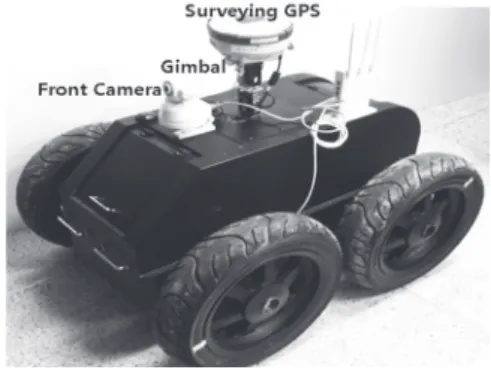
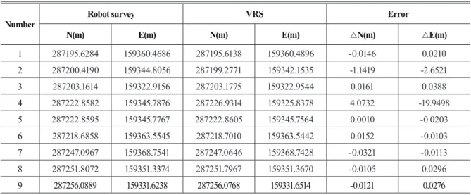
This study is about the auto-surveying system development, based on VRS-GPS, which enables auto-drive in dangerous areas, whereas difficult for humans to measure directly. The GPS is made with GRXI and SHC250 controllers of the SOKKIA company. The auto surveying system is composed of DPS module, geomagnetism sensor, bluetooth, gimbals, IMU, etc to automatic drive via enter into a route of position. The developed auto surveying system has installed the carmeras for front and vertical axis as well as systems to grasp situation of surveying with smartphone in real time. The result from analysed RMSE of auto surveying system and VRS- GPS surveying is 0.0169m of X-axis and 0.0246m of Y-axis.
Keywords : VRS-GPS, Geomatics information, Auto surveying system, Geomagnetism sensor, IMU
253 ISSN 1598-4850(Print) ISSN 2288-260X(Online) Original article
Received 2014. 05. 28, Revised 2014. 06. 19, Accepted 2014. 06. 29
1) Corresponding Author, Member, Dept. of Civil Engineering, Kyungnam University(E-mail: [email protected]) 2) Member, Dept. of Civil Engineering, Kyungnam University(E-mail: [email protected])
3) Gyeongnam Province Hall, Dept. of Civil Engineering, Pusan National University(E-mail: woosik45@ korea.kr)
This is an Open Access article distributed under the terms of the Creative Commons Attribution Non-Commercial License (http://
creativecommons.org/licenses/by-nc/3.0) which permits unrestricted non-commercial use, distribution, and reproduction in any medium, provided the original work is properly cited.
1. Introduction
The expressway network connecting every part of the country begins with Gyeongin Expressway and with the Ulsan Industrial Complex as the beginning point of approximately 1,000 industrial complexes. This describes that the Republic of Korea has achieved the industrial progress, well as stood at the high progress status. At grand scale construction sites, such as expressway or industrial complex sites, 1 person survey system, called GPS, was introduced to get away from the existing survey systems of the Total-Station, required many people. The GPS survey equipment, which are mostly expensive, huge and heavy, requires 3 or more equipments, since there should be installed equipments, which one fixed at 2 or more base stations and
the other at an unknown point; therefore, GPS hardly is a 1 person survey system. As a solution to the inconveniences the National Geographic Information Institute under the Ministry of Land, Infrastructure and Transport is operating 51 regular observatories throughout the country to make it suitable for the real 1 person survey.
Recently, research on automatic positioning system is lively proceeding with unmanned helicopter in its center. In order to build an automatic system, the research is essentially held under the structure of GPS combinations. This concludes that the robot and the GPS are in an indivisible relationship. In 2003, Kim and Kim(2003) designed an autonomous mobile control system to load it on a robot car and conducted a research that the car doing an autonomous drive with the pre-programmed system. They received the input data of
Journal of the Korean Society of Surveying, Geodesy, Photogrammetry and Cartography, Vol. 32, No. 3, 253-259, 2014
254
transverse and longitudinal control necessary for driving via satellite by a GPS receiver and for the live time and the correction input sensor they used a magnetic compass and a 3-side gyro. The autonomous drive of the robot car proved that it was possible by just using the GPS data. Lee et al.(2010) suggested using a mathematical model to control the moving robot. Also, there was a research in 2009 about an underwater cleaning robot and its envisioned the propulsive performance of the robot of joystick and computer(Choi et al., 2009). To interpret coordinates of the robot, they express it through a fixed coordinate of a certain place on the Earth and a fixed coordinate in the body of the underwater robot.
To examine the VRS-GPS related research in Korea, Choi et al.(2004) has suggested an optimization plan of the system composition, operation and application to improve the general satellite positioning system services through an effective usage of GPS regular observatory. Also, to solve the problem of increasing position errors proportional to distances from the base station, when RTK(Real Time Kinematic) surveying using GPS, the National Geographic Information Institute have built VRS(Virtual Reference System) RTK system, which is a type of Network RTK(Kim et al., 2008). Yun et al.(2010) carried out a survey with the VRS service, offered by the National Geographic Information Institute. They evaluated the result of the survey with theresult of cadastral topographic control point and the accuracy and the result of Total-Station survey and suggested the possibility of utilizing the VRS survey. Choi and Kim(2012) acquired data through means of the hypothetical base station on the cadastral control point, they analyzed it by comparing with the result from observing the cadastral control point for utilizing the Total- Station with the repetition method.
Acquiring spatial data via VRS-GPS is an excellent method. However the system faces many situational restrictions, which requires a lot of personnel, considered as the inefficiency of expanse and time; it calls for the necessity of the new survey system. On these days, there is an arousing necessity on automatic machineries could be substituted with human beings in dangerous area, hard work and simple tasks. To practice those automatic machines to replace human beings, it is necessary to develop high technical robots from a lot of studies and different areas. In Korea, researches are
undergoing for aerial survey and bathymetric survey areas for using RC robots, but there is none in topographic survey area that requires a lot of people and time. Also, the main stream of progressing researches on robots is the simple utilization of GPS for autonomous driving, so there are scarcely any researches on precise surveys. Therefore, in our research, we are going to develop a GPS positioning system able to do autonomous driving and analyze the existing VRS survey and its accuracy.
2. Basic Theory
2.1 Graded driving robot model
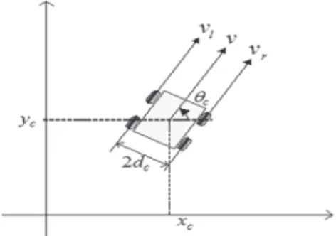
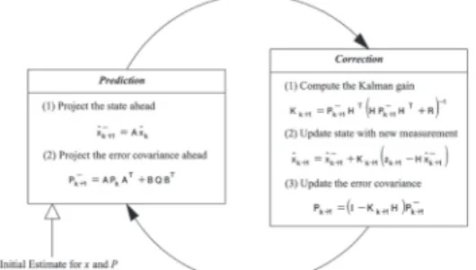
In this research the mobile robot estimates the user by utilizing the GPS positional information and the geomagnetic sensor azimuth information from distance. The GPS positional information includes error information. In this study Kalman filter is used to correct the error of the positional information caused by GPS. Mobile robot’s theory of mechanism is necessary in order to apply Kalman filter. Fig.1 show the mechanism theory of the GPS Survey robot related Eq.(1).
(1)
where the motional model of the mobile robot is expressed as robot related Eq.(1).
cos
cos·
(1)
sin
sin·
, 3 vectors. stands for the middle position of the mobile robot, represents the azimuth of the mobile robot for the axis of the normal coordinate. And is the horizontal distance between the middle position of the mobile robot and the wheels of each direction. Eq.(2) explain the linear velocity and the angular speed of the mobile robot.
(2)
Where, and are the linear velocity of the contact point of the wheels of each direction and the ground and the subscript and represent the right and the left wheel. and shows the speed of revolution of both wheels. And represents the radius of the wheel.
vector by the GPS positional information and the azimuth of the magnetic geomagnetic sensor. The position of the survey point is also read as vector
In Eq. (2) to decide on the linear velocity and the angle speed the speed
of the right and left wheels are set as below by the modulating control machine. (Eq. (3))
=
= (3)
Eq. (4) explain and , where the control variables, the distance between the mobile robot and the survey point, , and the azimuth difference
, 3 vectors. This of robot related Eq.(1).
cos
cos·
(1)
sin
sin·
, 3 vectors. stands for the middle position of the mobile robot, represents the azimuth of the mobile robot for the axis of the normal coordinate. And is the horizontal distance between the middle position of the mobile robot and the wheels of each direction. Eq.(2) explain the linear velocity and the angular speed of the mobile robot.
(2)
Where, and are the linear velocity of the contact point of the wheels of each direction and the ground and the subscript and represent the right and the left wheel. and shows the speed of revolution of both wheels. And represents the radius of the wheel.
vector by the GPS positional information and the azimuth of the magnetic geomagnetic sensor. The position of the survey point is also read as vector
In Eq. (2) to decide on the linear velocity and the angle speed the speed
of the right and left wheels are set as below by the modulating control machine. (Eq. (3))
=
= (3)
Eq. (4) explain and , where the control variables, the distance between the mobile robot and the survey point, , and the azimuth difference
stands for the middle position of tmobile robot, and
robot related Eq.(1).
cos
cos·
(1)
sin
sin·
, 3 vectors. stands for the middle position of the mobile robot, represents the azimuth of the mobile robot for the axis of the normal coordinate. And is the horizontal distance between the middle position of the mobile robot and the wheels of each direction. Eq.(2) explain the linear velocity and the angular speed of the mobile robot.
(2)
Where, and are the linear velocity of the contact point of the wheels of each direction and the ground and the subscript and represent the right and the left wheel. and shows the speed of revolution of both wheels. And represents the radius of the wheel.
vector by the GPS positional information and the azimuth of the magnetic geomagnetic sensor. The position of the survey point is also read as vector
In Eq. (2) to decide on the linear velocity and the angle speed the speed
of the right and left wheels are set as below by the modulating control machine. (Eq. (3))
=
= (3)
Eq. (4) explain and , where the control variables, the distance between the mobile robot and the survey point, , and the azimuth difference
represents the azimuth of the mobile robot for the axis of the normal coordinate. A variable, robot related Eq.(1).
cos
cos·
(1)
sin
sin·
, 3 vectors. stands for the middle position of the mobile robot, represents the azimuth of the mobile robot for the axis of the normal coordinate. And is the horizontal distance between the middle position of the mobile robot and the wheels of each direction. Eq.(2) explain the linear velocity and the angular speed of the mobile robot.
(2)
Where, and are the linear velocity of the contact point of the wheels of each direction and the ground and the subscript and represent the right and the left wheel. and shows the speed of revolution of both wheels. And represents the radius of the wheel.
vector by the GPS positional information and the azimuth of the magnetic geomagnetic sensor. The position of the survey point is also read as vector
In Eq. (2) to decide on the linear velocity and the angle speed the speed
of the right and left wheels are set as below by the modulating control machine. (Eq. (3))
=
= (3)
Eq. (4) explain and , where the control variables, the distance between the mobile robot and the survey point, , and the azimuth difference , is the horizontal distance between the middle position of robot related Eq.(1).
cos
cos·
(1)
sin
sin·
, 3 vectors. stands for the middle position of the mobile robot, represents the azimuth of the mobile robot for the axis of the normal coordinate. And is the horizontal distance between the middle position of the mobile robot and the wheels of each direction. Eq.(2) explain the linear velocity and the angular speed of the mobile robot.
(2)
Where, and are the linear velocity of the contact point of the wheels of each direction and the ground and the subscript and represent the right and the left wheel. and shows the speed of revolution of both wheels. And represents the radius of the wheel.
vector by the GPS positional information and the azimuth of the magnetic geomagnetic sensor. The position of the survey point is also read as vector
In Eq. (2) to decide on the linear velocity and the angle speed the speed
of the right and left wheels are set as below by the modulating control machine. (Eq. (3))
=
= (3)
Eq. (4) explain and , where the control variables, the distance between the mobile robot and the survey point, , and the azimuth difference
Fig. 1. Kinematic system of the GPS surveying robot