• 검색 결과가 없습니다.

High-Efficiency Heterojunction with Intrinsic Thin-Layer Solar Cells: A Review

N/A
N/A
Protected

Academic year: 2021

Share "High-Efficiency Heterojunction with Intrinsic Thin-Layer Solar Cells: A Review"

Copied!
9
0
0

로드 중.... (전체 텍스트 보기)

전체 글

(1)

Nomenclature

a-Si:H/c-Si : hydrogenated amorphous silicon/crystalline silicon HJ : heterojunction

HIT: Heterojunction with Intrinsic Thin-layer a-Si:H(i): intrinsic hydrogenated amorphous silicon BSF: back surface field

V

oc

: open-circuit voltage J

sc

: short-circuit current density FF: fill factor

η: efficiency

J-V: current density-Voltage TCO: transparent conductive oxide ATR: attenuated total reflection

MTCE: multi-tunnelling capture-emission

PECVD: plasma enhanced chemical vapour deposition VHF-PECVD: very high frequency PECVD

HWCVD: hot wire CVD

SKKU: Sungkyunkwan University ITO: indium tin oxide

IO:H: hydrogenated doped indium oxide

ZnO:Al: aluminium doped zinc oxide V
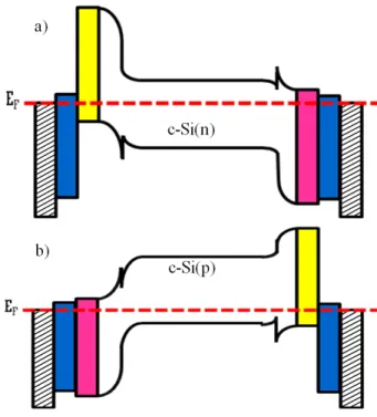
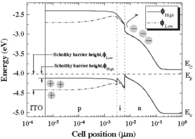
D

: built-in potentials

Φ: work function

D

it

: defect states at the a-Si:H/c-Si interface N

DB

: defect states in the a-Si:H bulk SE: spectroscopic ellipsometry SHG: second-harmonic generation XPS: X-ray photospectroscopy UPS: ultra-violet photospectroscopy

UV-PYS: ultraviolet-excited photoelectron yield photospectroscopy TEM: transmission electron microscopy

SIMS: secondary ion mass spectroscopy QSSPC: quasi-steady-state photoconductance µc-Si:H: hydrogenated microcrystalline silicon a-SiO

x

:H: hydrogenated amorphous silicon oxide SiN

x

: silicon nitride

ICDL: Information and Communication Device-Lab

AIST: The National institute of Advanced Industrial Science and Technology

HZB: Helmholtz Zentrum Berlin

EPFL: École Polytechnique Fédérale de Lausanne NREL: National Research Energy Laboratory

High-Efficiency Heterojunction with Intrinsic Thin-Layer Solar Cells: A Review

Vinh Ai Dao

1)

* ․ Sangho Kim

2)

․ Youngseok Lee

2)

․ Sunbo Kim

2)

․ Jinjoo Park

1)

․ Shihyun Ahn

1)

․ Junsin Yi

1,2)

*

1)

School of Information and Communication Engineering, Sungkyunkwan University, Suwon, 440-746, Korea

2)

Department of Energy Science, Sungkyunkwan University, Suwon, 440-746, Korea

ABSTRACT: Heterojunction with Intrinsic Thin-layer (HIT) solar cells are currently an important subject in industrial trends for thinner solar cell wafers due to the low-temperature of production processes, which is around 200°C, and due to their high-efficiency of 24.7%, as reported by the Panasonic (Sanyo) group. The use of thinner wafers and the enhancement of cell performance with fabrication at low temperature have been special interests of the researchers. The fundamental understanding of the band bending structures, choice of materials, fabrication process, and nano-scale characterization methods to provide necessary understanding of the interface passivation mechanisms, emitter properties, and requirements for transparent oxide conductive layers is presented in this review. This information should be used for the performance characterization of the developing technologies for HIT solar cells.

Key words: Heterojunction, Photovoltaics, High efficiency, c-Si interface, Solar cells

*Corresponding author: [email protected], [email protected] Received November 20, 2013; Revised November 29, 2013;

Accepted December 2, 2013

ⓒ 2013 by Korea Photovoltaic Society

This is an Open Access article distributed under the terms of the Creative Commons Attribution Non-Commercial License (http://creativecommons.org/licenses/by-nc/3.0)

which permits unrestricted non-commercial use, distribution, and reproduction in any medium, provided the original work is properly cited.

73

(2)

Subscripts

ITO: indium tin oxide oc: open-circuit sc: short-circuit it: interface states

DB: defect states in a-Si:H bulk

1. Introduction

Wafer bowing and breakage caused by high-temperature metal back contact is a great concern due to the current industry trend toward thinner solar cell wafers. The a-Si:H/c-Si HJ solar cell is a good solution to these problems due to the low- temperature of the production process, which is around 200°C.

This also limits the thermal budget and allows for inexpensive, lower-quality materials to be used as base materials. A considerable number of studies have been made on the a-Si:H/c-Si heterojunction solar cells in recent years

1-8)

. Panasonic’s (Sanyo) HIT solar cells hold the word record efficiency of 24.7% based on n-type c-Si wafers, in which stacks of a-Si:H(i) and doped a-Si:H layers help form both the emitter and the BSF

1)

. The a-Si:H(i) layer enables very high V

oc

due to its excellent passivating properties.

Hence, this incorporation of the a-Si:H(i) layer at the hetero- interface has been confirmed to improve solar cell η

2)

.

The first investigation of the HJ silicon solar cells, in which an amorphous silicon emitter is deposited on a crystalline substrate, was reported by Fuhs et al. in 1974

9)

. Then, in 1985, the HJ solar cell was fabricated with SiO

2

depositing on both sides of p-type c-Si substrates by Yablonovitch et al

10)

. For maximal performance, Yablonovitch stated that solar cells should resemble semiconductor lasers, i.e., in that they should be constructed in the form of a double HJ. In this configuration, a narrow-band-gap active layer such as a c-Si absorber layer is sandwiched between two wide band-gap layers of opposite doping, which act as a “carrier mirror”. Hence, the less recombination at the contact could be achieved. Moreover, it was also stated that in order to achieve high V

oc

, the use of higher-quality wafer and lower surface recombination are other key issues

10)

. The technical base on a-Si:H/c-Si HJ as an alternative to traditional diffused emitters have been investigated by many research groups using both n- and p-type absorber layers

1,8,12-13)

. The mass production of this type of cell was also established as

performance of the a-Si:H/c-Si HJ solar cell has been published by Q. Wang

15)

. Instead of focusing on these issues, this review focuses on the physical characteristics, such as the band diagram, carrier transport, and device characterization in order to highlight the key issues in a-Si:H/c-Si HJ solar cells. The recent leading performance of the HIT solar cells fabricated at various companies and institutes all over the world are also reported.

2. The construction of the a-Si:H/c-Si HJ band diagram

An energy band diagram of a double-side a-Si:H/c-Si HJ solar cells is shown in Fig. 1. In this figure, the value of the band gap for p-type, n-type, and i-type a-Si:H is assumed to be the same (with a negligible number of states). Since the vacuum level is parallel everywhere to the band edges and is continuous

16)

. As a result, the electron affinities and band gap define the band discontinuities at the interface. The band discontinuities at the interface are also called the “band offset”. The band offset (valence and conduction) appears at both the front and back side of the HJ. The band offset plays a significant role in the carrier transport in the heterojunction solar cells. At the front side, with

Fig. 1. Schematic band diagram of HIT solar cells based on (a) c-Si(n) and (b) c-Si(p) substrates. An indication of the metal contact, ITO, a-Si:H(p), and a-Si:H(n), , , ,

, respectively is given in the band diagram

(3)

an increasing band offset, the Fermi level position at the HJ shifts towards the valence band (conduction band) edge of c-Si (n/p), this reduces the interface recombination efficiency

17)

. Simultaneously, the built-in potential is also enhanced when the barrier in the band offset becomes larger. This enhances V

oc

, thus yielding higher conversion efficiency. However, when the band offset exceeded the value of 0.56 eV, the deformation of J-V characteristics was observed due to free-hole accumulations at the interface

18)

, as shown in Fig. 2. This leads to a deep depletion at the interface. Hence, the hole current is nearly suppressed, eventually resulting in a lower J

sc

and low FF. The preferred value of the band offset is around of 0.54 eV, which can be controlled by the energy band gap of the emitter as well as the a-Si:H(i) layer

6,18)

. At the back side, the value of the band offset and behaviour of the carrier transport depend on the doping type of the base wafers. For example, for an n-type substrate, the large valence band offset and thicker a-Si:H(i) layer provide a back surface “mirror” for holes. This a-Si:H(i/n) stack does not affect electron transport much because the offset in the conduction band edges is small

4)

. In contrast, the small conduction band offset provides a much less effective mirror for the minority carrier electrons. Additionally, the larger offset in the valence band edges prevent hole collection, resulting in the accumulation of holes on the back side of the c-Si surface and a consequent reduction in the FF and conversion efficiency

4)

.

The ϕ

TCO

is also another key issue to take into account in device design, because it can be influence the total built-in potential of the device. Without regard to the doping type of the substrate, if the ITO work function is not appropriate, the built-in potentials ( V

D

) of TCO/a-Si:H contact and a-Si:H/c-Si junction will have opposite directions to each other. With an

n-type c-Si substrate, for instance, ITO with higher ϕ is preferable, because it determines a higher built-in voltage and therefore higher V

oc

and η. ITO with lower ϕ not only determines a lower built-in voltage, but can also induce the formation of an inverted Schottky junction at the interface of the ITO/emitter, which can reduce or even cancel out the device performance

19)

, as shown in Fig. 3. We can apply this understanding of the effects of ϕ

TCO

to p-type c-Si substrate. In order to obtain a high-efficiency HIT device, ϕ

TCO

should at least be lower than 4.5 eV or higher than 5.1 eV for p- or n-type c-Si substrates, respectively. A ϕ

TCO

value of 5.1 eV can be obtained in practice, which may be one reason for Sanyo achieving the world record efficiency of 24.7% on n-type silicon substrate

20-22)

.

3. Material choice for c-Si surface passivation and carrier transport in a-Si/c-Si HJ solar cells

3.1 Material choice for c-Si surface passivation Due to the largest disturbance to the symmetry of the crystal lattice, non-saturated or dangling bonds are formed at the surface. Additional process-related extrinsic surface defects may arise from dislocation or chemical residues and metallic deposition on the surface. Those defects become recombination centers for photogenerated carriers. Thus, surface recombination losses at the c-Si surface will be at tolerable levels if they are well passivated. A low surface recombination of less than 10 cm/s has been achieved in different ways by the use of a dielectric layer such as SiO

2

, SiN

x

or a-Si:H

7,24-26)

. However, a-Si:H is the best choice for a-Si:H/c-Si heterojunctions due to Fig. 2. Variation of the illumination J-V characteristics for different

valence band discontinuities and activation energies of the emitter in c-Si(n) double HIT solar cells

6)

Fig. 3. Band diagram of the ITO/a-Si:H(p)/ a-Si:H(i)/c-Si(n)

structure with low and high ϕ

TCO23)

(4)

its lesser restriction of the carrier transport. A thin layer of high-band-gap material such SiO

2

or SiN

x

in place of the a-Si:H layer results in barrier potential and then blocking of the carrier transport, causing an S-shape in the J-V characteristics. By restricting the band gap of SiO

2

to less than 2 eV, HJ solar cells can succeed in preventing the S-shape in the J-V curve

27)

.

Thus, if the passivation by a-Si:H(i) is good enough and the band offset is suitable, the photogenerated charge carriers in the c-Si absorber can be separated, resulting in less surface recombination and high V

oc

. The carriers which survive from the surface recombination process then become the victim of the localized states in the emitter layer and the states in the vicinity of the emitter/buffer layer interface, as shown in Fig. 4. The higher conductivity resulting in the shift of the Fermi level to near the band edge (valence or conduction) leads to enhancement of V

oc

. However, the higher doped layers own to larger mid-gap defects than undoped ones. The mid-gap defects are the major source for the absorption of light as well as photogenerated carrier recombination. Hence, the trade-off condition for an emitter layer with lower mid-gap defects and higher conductivity are also important factors for higher HIT cell performance.

3.2 Carrier transport in the a-Si/c-Si HJ solar cells Carrier transport in the a-Si:H/c-Si HJ can be unique and different from the conventional p-n solar cell because the Fermi level can be varied by doping. The MTCE model was first suggested by Matsuura et al. to explain the dark forward J-V characteristics of a thick (~1 µm) a-Si:H(i)/c-Si(p) HJ

28)

. In concurrence with Matsuura et al., Mimura and Hatanaka confirmed that MTCE dominated in their HJ, which is an undoped thick a-Si:H (~ 1 µm), or slightly B-doped a-Si:H grown on n-type c-Si

29)

. Rubinelli et al. supported Matsuura’s multitunnelling model in their theoretical evaluation of the a-Si:H(n)/c-Si(p) HJ

30)

.

other model, which is the diffusion current, is suggested. Two decades after the first HIT cell was made, the first investigation of the mechanisms of carrier transport in HIT solar cells was reported by Taguchi et al. They stated that the diffusion model determined the carrier transport properties of their solar cell device in the high-forward-bias region (0.4 < V < 0.8 V), whereas the multistep tunnelling model determined the current transport in the low-bias region (0.1 < V < 0.4 V)

31)

. Based on the HIT structure, T. F. Schulze et al. suggested that the transport mechanism is dependent on the substrate doping type. The most relevant microscopic parameter “the interface passivation quality”

mainly impacts the high-forward-bias current, thus determining V

oc

. In the low-forward-bias range, while the n-type c-Si based samples exhibit a current dominated by recombination in the space charge region, the p-type c-Si based samples reveal a dominating temperature-independent tunnelling contribution

32)

. Recently, Dao et al. revealed that in the low-forward-bias region, a HJ solar cell fabricated on n-type c-Si is dominated by the MTCE mechanism. The diffusion-recombination current is denominated the in high-forward-bias region

7)

. Consequently, the conduction mechanisms in the forward-bias range of the HJ with intrinsic thin layer solar cells have been ambiguous.

4. The a-Si/c-Si heterojunction solar cell process

From left to right, in Fig. 1, the most commonly symmetrical HIT solar cell includes a metal grid, transparent conducting oxide (TCO such as ITO, ZnO:Al, IO:H), emitter layer (a-Si:H (p- or n-type)), passivated-layer (a-Si:H(i), a-SiO

x

:H(i)), bulk absorber layer (n or p-type c-Si), passivated-layer (a-Si:H(i), a-SiO

x

:H(i)), BSF layer (a-Si:H(n- or p-type)), TCO, and finally the back metal contact. Photolithography or patterned physical masks could be used for defining an area and front grid formation with approximately 5% area coverage. Commonly, an evaporated multi-layer stack of Ag/Al is used for the top metal contact. A multi-layer stack of Ti/Pd/Ag can also be used.

In this stack, Pd is used to prevent Ag from diffusing in or out.

Al or Ag/Al, or a stack of Ti/Pd/Ag/Pd is used for bottom contact formation. The screen-printing of silver-paste as fingers for the front electrode and the entire rear surface for the back contact for larger-area cells was applied for industrial cells.

In order to enhance the light trapping, the substrate surface is Fig. 4. Schematic band diagram of a-Si:H(p)/ a-Si:H(i)/c-Si(n)

HJ including defect states at the a-Si:H/c-Si interface,

D

it

and the a-Si:H bulk-defect, N

DB

(5)

textured. By appropriate selective etching microscopic pyramids are created. Mono-Si is available with various surface directions, e. g. the (110), (111), and (100) directions. The removal rate for alkaline etches such as KOH or NaOH is different for different crystal planes. Under appreciate conditions small pyramids can be produced based on this effect.

Before depositing any layer on the c-Si surface, it must be cleaned from organic and inorganic impurities from saw damage and surface impurities. A process using acetone/methanol, DIW rinse, RCA1, DIW rinse, RCA2, and then HF dipping has been well established. A final cleaning with 1-5% HF was applied to the c-Si wafer before loading it into the chamber for cell fabrication.

After wafer cleaning, the wafer was loaded immediately into the chamber. The intrinsic passivated layer and emitter layer are deposited in sequence for front-side fabrication. Turning back the wafers, the intrinsic passivated and back-surface fields are then deposited for back-side formation. The optimized deposition conditions of the intrinsic passivated layer depend on the deposition technique and wafer surface. However, we have to ensure that there is no epitaxial or microcrystalline growth on the c-Si surface. Moreover, a film with fewer voids, and higher hydrogen content is more attractive

7)

. For doped layer deposition condition, a large conductivity and higher thickness in an emitter layer are accompanied by larger light absorption in the blue and near-infrared regions and a middle-band gap defect.

Therefore, the trade-off conditions for the emitter layer are sought effective application to solar cell fabrication

33)

.

For all a-Si:H deposition, the most common deposition technique is PECVD

8)

. The VHF-PECVD technique has also appeared as an interesting alternative for conventional PECVD methods. This allows for higher deposition rates and it is less aggressive than the conventional PECVD technique. VHF-PECVD was also achieved by a group at SKKU

34)

. Another technique, HWCVD, also showed suitable a-Si:H layer deposition due to its higher deposition rates and being less aggressive than conventional PECVD

13)

.

Current collection just by the front grid would lead to high losses. The amorphous emitter layer exhibits a low lateral conductance due to the small conductivity and small thickness (~ 7 – 15 nm). Hence, a transparent conductive oxide layer is introduced between the emitter and the metal contact. Achieving the lowest possible electrical resistivity with the optimized highest transparency in the visible range is a requirement for the

unique properties of the TCO layer. ITO is one of the most used materials for TCO contact due to its high band gap of 3.75 eV and low resistivity of ~10

-4

Ω․cm. Magnetron sputtering with a ceramic target is a common method for ITO deposition, in which Ar feed gas and substrate heating to ~200°C are used during deposition

35)

. ZnO:Al is also another choice for the anti-reflection layer in HJ solar cells. Recently, IO:H has shown some advantages over conventional ITO due to its high conductivity, low carrier concentration and high mobility. The current density of IO:H can be enhanced in a device due to low free-carrier absorption

36)

. For all kinds of TCO, the thickness is fixed approximately 80 nm respect to refractive index of 1.8 at 550 nm of wavelength.

5. Characterization methods

An effective a-Si:H/c-Si interface that allows for the efficient transport of charge carriers with minimal recombination loss is a prerequisite for high-performance HJ solar cells, in which a thin a-Si:H(i) layer is generally interposed between the base wafer and heavily doped emitter. Purely hydrogenated intrinsic amorphous silicon, highest hydrogen content, and lowest void fraction are designed properties for the passivated c-Si wafer.

The passivation of a silicon surface can be achieved in two ways: by field-effect passivation or by the neutralization of defects of interface states. Infrared absorption techniques, such as ATR can provide information on SiH

n

(n = 1-3) local structures with sensitivity. The higher Si-H bond is utilized for the neutralization of interface defects, whereas a-Si:H(i) contains an Si-H

2

-rich interface, resulting in porous structures and poor surface passivation

37-38)

. Using in-situ SE or SHG techniques, the formation of both amorphous silicon and epitaxial films on c-Si can be investigated from a very early stage of film growth.

The growing of an epitaxial layer as well as void formation at the

interface could be suppress the passivated quality of the films

39)

.

The formation of Si thin films has also been studied using ex-situ

techniques such as TEM and SIMS, which provide detailed

information on film structures and composition, but cost, time

effectiveness, and sample destruction are known issues. Other

ex-situ techniques that are non-destructive could be XPS, UPS,

and UV-PYS. The recombination rate could be evaluated

through the density of band gap states in the a-Si:H layer. The

higher density of band gap states results in higher recombination

at the a-Si:H/c-Si interface due to the photogenerated carriers

(6)

Finally, the QSSPC technique is an ex-situ technique, but it provides a direct and clear value of abruptness of the a-Si:H/c-Si interface. Hence, this method is used as a reference for the evaluation of other techniques.

Accompanying the a-Si:H layer, TCO and the TCO/emitter interface are other key issues for achieving high-efficiency HIT solar cells. The formation of Si-O bonds on the ITO/a-Si:H interface during the initial stages of ITO growth results in the appearance of a thin SiO

x

layer in this region. This can act as a barrier for the carrier transport at the front contact. Moreover, high-energy sputtered atoms, such as In and Sn can penetrate in to the a-Si or Si bulk layer. This leads to the formation of complicated HJ structures near the a-Si:H/c-Si interface region.

For all of these phenomena, XPS and SIMS can be used

41-42)

.

6. Leading research and development of HIT solar cells

The Sanyo research and development group was the first to apply an a-Si:H HJ to a c-Si solar cell in 1991

43)

. An efficiency of 12.3% was obtained with their first HJ junction solar cell by directly depositing an a-Si:H(p) layer onto an n-type c-Si wafer.

Due to the high defect-state density at the herointerface, the solar cell shows relatively low V

oc

and FF. Inserting of a thin a-Si:H(i) layer between a-Si:H(p) and n-type c-Si wafer lead to better cell performance. This incorporation of a-Si:H(i) lead to passivation of the dangling bonds on the c-Si surface, which lowered the a-Si:H/c-Si interface defect-state density. This lower defect-state density at the HJ interface led to improvement of the V

oc

and FF. Using a passivated a-Si:H(i) layer, the highest efficiency of 14.8% was obtained for HIT solar cells

43)

. A cell efficiency of 18.1% was achieved with the textured wafer surface for light trapping and the incorporation of a BSF on the back side of the device

43)

. The incorporation of a textured wafer surface and the incorporation of a BSF led to a significant increase in J

sc

. The performance of the HIT solar cell was further improved by applying double-side passivated a-Si:H(i) to the wafer. At the same time, ITO was also included in the back side between the BSF and metal-grid electrode. This designed structure was called a symmetrical HIT solar cell. This symmetrical HIT structure helps to suppress the thermal and mechanical stress in the wafers, which occur due to the

from both sides. Consequently, the applied both-side surface passivation and ITO incorporation onto BSF enabled HIT solar cell efficiencies of up to 21.3%

44)

. The structure of the HIT solar cell is no longer developed, while the cell efficiency still keeps rising by the optimization of each-layer. By 2008, after applying a new cleaning process, the depositing a high-quality a-Si:H(i) layer, and reducing the plasma and/or thermal damage to c-Si surface during a-Si:H, TCO, and conductive electrode fabrication, an HIT cell open-circuit voltage and efficiencies as high as 725 mV and 22.3% was obtained, respectively

45)

. With the same key approach, in 2009, the conversion efficiency of HIT solar cell reached a level of 23% for a 100.4 cm

2

practical-size crystalline silicon substrate (V

oc

: 729 mV, J

sc

: 39.52 mA.cm

2

, FF: 80.0%).

At the same time, Sanyo was also trying to fabricate thinner HIT cells with thickness below 100 µm

45)

. With these thinner cells, the J

sc

decreases slightly, but V

oc

increases significantly, from 729 mV to 743 mV. This achievement is attributed to the extremely low bulk recombination. From this time, they focused on developing technologies for higher conversion efficiency with thin c-Si wafer (98 µm) with the aim of reducing cost. Since they announced their former record of 23.7%

46)

, in 2011, they have continued to reduce recombination losses at the a-Si/c-Si heterointerface along with cutting down resistive losses by improving the silver paste with lower resistivity and optimization of the thickness in a-Si:H layers. Currently, Panasonic (Sanyo) obtained a new world record efficiency of 24.7% (V

oc

: 750 mV, J

sc

: 39.5 mA/cm

2

and FF: 83.2%) at the research level with a

Fig. 5. Development of HIT solar cell efficiency vs. time, all over

the world. 1 to 10 indicates the HIT solar cell efficiency of

Sanyo (200 µm thick-wafer), Panasonic (Sanyo 98 µm

thick-wafer), HZB, EPFL, NREL, SKKU, Kanaka/Imes,

Roth & Rau, AIST and INEA, respectively

(7)

practical-size of 101.8 cm

2 22)

.

Many research groups are following Sanyo’s lead to work on HIT solar cells due to their high performance and low-temperature processing. Fig. 5 depicts the performance of the leading HIT solar cells at several companies and institutes all over the world.

In 2008, at the Neuchatel PV-lab of EPFL, in order to enhance the carrier extraction, a new highly conductive doped µc-Si:H layer was used as an emitter and BSF for HIT solar cells

24)

. With this approach, the EPFL can obtain a cell efficiency of 19.1%

without surface texturing. An efficiency of 17.5% was obtained by AIST

27)

in 2009, for which a new a-SiO

x

:H passivated layer for HIT solar cells was used. The thinning of the wafer to below 100 µm was also investigated; but this thinner wafer led to reduction of both J

sc

and V

oc

. This result is contrary to Sanyo’s results

22)

. By 2010, Roth et al. with the EPFL used the S-Cubed reactor to demonstrate efficiency of up to 21%, which is the second highest efficiency achieved, at this time

47)

. the ICDL of SKKU introduced a stacked-emitter and LiF-back contact to fabricate HIT solar cells, in order to enhance the carrier collection for both front and back contact. Using this HIT structure approach, the ICDL obtained efficiency as high as 20.6%

48)

. By 2012, a second record efficiency of 22.8% on a six inch semi- square was achieved by Japan’s Kanenka Corporation with Belgium-based Imes. Their high efficiency is attributed to electroplated copper contact grid

49)

.

Without using any passivated layer, HZB can obtain efficiency as high as 19.8% based on a textured wafer

8)

. The high efficiency is attributed to the smoothing procedure after textured-surface and hydrogen post-treatment. This smoothing procedure and hydrogen post-treatment led to surface uniformity with less micro-roughness and improved a-Si:H film quality. In order to suppress ion bombardment of the surface, the HWCVD method for depositing a-Si:H layers was investigated by Wang et al.

15)

An efficiency of 19.1% was reported.

Conclusions

Based on this, we may conclude the following.

At the front side, a large band offset at the interface results in larger built-in potential, thus yielding higher V

oc

and cell performances. However with the band offset exceeding the value of 0.56 eV, it becomes a blocking layer for the carrier transport, resulting in deformation of the J-V characteristics. At

the back side, the value of the band offset and behaviour of the carrier transport depend on the type of base-wafers. The ϕ

TCO

should at least lower be than 4.5 eV or higher than 5.1 eV for p- or n-type c-Si substrates, respectively.

The carrier transport mechanisms in HIT solar cells tend to be ambiguous. However, it looks like that at the low-forward-bias region (V < 0.4 V), MTCE dominates; and at the high-forward- bias region (V > 0.4 V), both the diffusion and recombination mechanisms dominate.

The buffer passivated layers with less crystallinity, highest hydrogen content, lowest void fraction and non-epitaxial growth on the c-Si surface during deposition are designed properties for interface passivation.

Using ATR-FTIR, the hydrogen bonding mode could be well understood. A very early stage of film growth could be observed by SE as well as SHG technique. TEM and SIMS techniques could also provide detailed information on film structures and composition, but cost, time-effectiveness, non in-situ operation and sample destruction remain as issues.

Currently, the world’s highest conversion efficiency of 24.7% with a 98 µm wafer of HIT solar cells for a total area of 101.8 cm

2

is held by the Panasonic (Sanyo) group.

Acknowledgments

This work was supported by Basic Science Research Program through the National Research Foundation of Korea (NRF) funded by the Ministry of Education (NRF-2013R1A1A 2064769).

References

1. Mishima, T., Taguchi, M., Sakata, H., Maruyama, M.,

“Development status of high-efficiency HIT solar cells,” Solar Energy Materials & Solar Cells, Vol. 95, No. 1, pp. 18-21, 2011.

2. Taguchi, M., Kawamoto, K., Tsuge, S., Baba, T., Sakata, S., Morizane, M., Uchihashi, K., Nakamura, N., Kiyama, S., and Oota, O., “HITTM cells-high-efficiency crystalline Si cells with novel structure,” Prog. Photovoltaics: Research and Applications, Vol. 503, No. 5, pp. 503-513, 2000.

3. Schmidt, M., Korte, L., Laades, A., Stangl, R., Schubert, C., Angermann, H., Conrad, E., Maydell, K. v., “Physical aspects of a-Si:H/c-Si hetero-junction solar cells,” Thin Solid Films, Vol. 515, No. 19, pp. 7475-7480, 2007.

4. Wang, T. H., Page, M. R., Iwaniczko, E., Levi, D. H., Yan, Y.,

(8)

Terao, A., “Toward better understanding and improvidence of silicon heterojunction solar cells,” The 14th Workshop on Crystalline Silicon Solar Cells and Modules, American, NREL Report No. CP-520-36669, pp.1-8, 2004.

5. van CLEEF, M. W. M., Rubinelli, F. A., Rizzoli, R., Pinghini, R., Schropp, R. E. I., and van der WEG, W. F., “Amorphous silicon carbide/crystalline silicon heterojunction solar cells: A comprehensive study of the potocarrier collection,” Jpn. J.

Appl. Phys. Vol. 31, No. 7, pp. 3926-3932, 1998.

6. Datta, A., Rahmouni, M., Nath, M., Boubekri, Roca I Cobarrocas, R., Chatterjee, P., “Insight gained from computer modeling of heterojunction with instrinsic thin layer “HIT” solar cells,”

Solar Energy Material & Solar Cells Vol. 94, No. 9, pp.

1457-1462, 2010.

7. Dao, V. A., Lee, Y. S., Kim, S. H., Kim, Y. K., Lakshminarayan, N., and Yi, J., “Interface characterization and electrical trans- port mechanisms in a-Si:H/c-Si heterojunction solar cells,”

Journal of The Electrochemical Society, Vol. 158, No. 3, pp.

312-317, 2011.

8. Korte, L., Conrad, E., Angermann, H., Stangl, R., Schmidt, M., “Advances in a-Si:H/c-Si heterojunction solar cell fab- rication and characterization,” Solar Energy Material & Solar Cells, Vol. 93, No. 6, pp. 905-910, 2009.

9. Fuhs, W., Niemann, K., and Stuke, J., “Heterojunction of amorphous silicon and silicon single crystals,” Bull. Am. Phys.

Soc. Vol. 20, pp. 345-349, 1974.

10. Yablonowith, E., Gmitter, T., Swanson, R. M., and Kwark, Y.

H., “A 720 mV open circuit voltage SiO

x

:c-Si:SiO

x

double het- erostructure solar cell,” Appl. Phys. Lett. Vol. 47, No. 11, pp.

1211-1213, 1985.

11. Damon-Lacoste, J., Roca I Cabarroscas, P., Gudovskikh, A.

S., Kleider, J. P., Riberron, P. J., and Veschetti, Y., “Plasma treatments of the interface in n-type a-Si:H/p-type c-Si hetero- junction silicon solar cells,” Proc. Of the 19

th

EU-PVSEC, Paris, 2, pp. 1453-1456, 2004.

12. Fesquet, L., Olibet, S., Vallat-Sauvain, E., Shah, A., Ballif., C.,

“High quality surface passivaion and heterojunction fab- rication by VHF-PECVD deposition of a-Si:H on c-Si theory and experiments” 22nd European Photovoltaic Solar Energy Conference 37 September 2007 Milan Italy (2007).

13. Wang, Q., Page, M. R., Iwaniczko, E., Xu, Y. Q., Roybal, L., Bauer, R., To, B., Yuan, H. C., Duda, A., and Yan, Y. F.,

“Crystal silicon heterojunction solar cells by hot-wire CVD,”

Presented at the 33

rd

IEEE Photovoltaic Specialists Conference San Diego, California, May 11-16, 2008.

14. Tanaka, M., Okamoto, S., Tsuge, S., and Kiyama, S., “Development of HIT solar cell with more than 21% conversion efficiency and commercialization of highest performance HIT modules,” 3

rd

World Conference on Photovoltaic energy Conversion, may 11-18, 2003 Japan, Osaka.

15. Wang, Q., “High-efficiency hydrogenated amorphous/crystal- line Si heterojunction solar cells,” Philosophical Magazine,

16. Anderson, R. L., “Experiments on Ge-GaAs heterojunctions,”

Solid-State Electronics Pergamon Press, Vol. 5, No. 5, pp.

341-351, 1962.

17. Fuhs, W., Korte, L., Schmidt, M., “Heterojunction of hydro- genated amorphous silicon and monocrystalline silicon,” Journal of Optoelectronics and Advanced Materials, Vol. 8, No. 6, pp.

1989-1995, 2006.

18. Dao, V. A., Lee, Y. S., Kim, S. H., Cho, J., Ahn, S., Kim, Y. K., Lakshminarayan, N., and Yi, J., Vol. 158, No. 11, pp.

1129-1132, 2011.

19. Centurioni, E., and Iencinella, D., “Role of front contact work function on amorphous silicon/crystalline silicon heterojunction solar cell performance,” IEEE Electron Device Letters, Vol. 24, No. 3, pp. 177-179, 2003.

20. Zhao, L., Zhou, C. L., Li, H. L., Diao, H. W., and Wang, W.

J., “Role of the work function of transparent conductive oxide on performance of amorphous/crystalline silicon hetero- junction solar cells studied by computer simulation,” phys. stat.

sol. (a), Vol. 205, No. 5, pp. 1215-1221, 2008.

21. Dao, V. A., Heo, J., Choi, H., Kim, Y. K., Park, S., Jung, S., Lakshminarayan, N., and Yi, J., “Simulation and study of the influence of the buffer intrinsic layer, back-surface field, den- sities of interface defects, resistivity of p-type silicon substrate and transparent conductive oxide on heterojunction with in- trinsic thin-layer (HIT) solar cell,” Solar Energy, Vol. 84, No. 5, pp. 777-783, 2010.

22. Taguchi, M., Yano, A., Tahoda, S., Matsuyama K., Nakamura, Y., Nishiwaki, T., Fujita, K., Maruyama, E., “24.7% Record efficiency HIT solar cell on thin silicon wafer,” IEEE J. of Photovoltaics, Vol. 4, No. 1, 2014.

23. Ahn, S., Kim, S., Dao, V. A., Lee, S., Iftiquar, S.M., Kim, D., Hussain, Q., Park, H., Lee, J., Lee, Y., Cho, J. Kim, S., Yi, J.,

“Interface barrier height modification of indium tin ox- ide/a-Si:H(p) via control density of density of interstitial oxy- gen for heterojunction solar cell application,” Thin Solid Films, Vol. 546, No. 1, pp. 342-346, 2013.

24. Olibet, S., Vallat-Sauvain, E., and Ballif, C., “Model for a-Si:H/c-Si interface recombination based on the amphoteric nature of silicon dangling bonds,” Physical Review B, Vol. 76, No. 3, pp. 1-13 2007.

25. Chen, Z., Pang, S. K., Yasutake, K., and Rohatgi, A.,

“Plasma-enhanced chemical-vapour-deposited oxide for low surface recombination velocity and high effective lifetime in sil- icon,” J. Appl. Phys. Vol. 74, No. 4, pp. 2856-2859, 1993.

26. S. Dauwe, Ph. D Thesis, University of Hannover, 2004.

27. Sritharathikhum, J., Banerjee, C., Otsubo, M., Sugiura, T., Yamamoto, H., Sato, T., Limmanee, A., Yamada, A., and Konagai, M., “Surface passivation of crystalline and poly- crystalline silicon using hydrogenated amorphous silicon oxide film,” Jpn. J. Appl. Phys. Vol. 46, No. 6A, pp. 3296-3300, 2007.

28. Matsuura, H., Okuno, T., Okushi, H., and Tanaka, K., J. Appl.

Phys., “Electrical properties of n-amorphous/p-crystaline sili-

(9)

con heterojunctions” Vol. 55, No. 4, pp. 1012-1019, 1984.

29. Mimura, H., and Hatanaka, Y., “Carrier transport mechanisms of p-type amorphous-n-type crystalline silicon heterojunctions”

J. Appl. Phys., Vol. 71, No. 5, pp. 2315-2320, 1992.

30. Rubinelli, F., Albornoz, S., and Buitrago, R., “Amorphous- crystalline silicon heterojunction: Trearetical evaluation of the current terms,” Solid-State Electron., Vol. 32, No. 10, pp.

813-825, 1989.

31. Taguchi, M., Maruyama, E., and Tanaka, M., “Temperature dependence of amorphous/crystalline silicon heterojunction solar cells,” J. Appl. Phys., Vol. 47, No. 2, pp. 814-818, 2008.

32. Schulze, T. F., Korte, L., Conrad, E., Schmidt, M., and Rech, B., “Electrical transport mechanisms in a-Si:H/c-Si hetero- junction solar cells,” J. Appl. Phys. Vol. 107, No. 2, pp. 1-13, 2010.

33. Maydell, K. v., Conrad, E., and Schmidt, M., “Efficient silicon heterojunction solar cells based on p- and n-type substrates processed at temperatures < 200°C,” Prog. Photovoltaics: Res.

Appl. Vol. 14, No. 4, pp. 289-295, 2006.

34. Dao, V. A., Ph. D Thesis, Sungkyunkwan University, 2011.

35. Dao, V. A., Choi, H., Heo, J., Park, H., Yoon, K., Lee, Y., Kim, Y., Lakshminarayan, N., and Yi, J., “rf-magnetron sput- tered ITO thin films for improved heterojunction solar cell ap- plications,” Curr. Appl. Phys. Vol. 10, pp. 506-509, 2010.

36. Koida, T., Fujiwara, H., and Kondo, M., “High-mobility hy- drogenated In

2

O

3

transparent conductive oxide for a-Si:H/c-Si heterojunction solar cells,” Solar Energy Materials & Solar Cells, Vol. 93, No. 6-7, pp. 851-854, 2009.

37. Fujiwara, H., and Kondo, M., “Real-time monitoring and process control in amorphous/crystalline silicon heterojunction solar cells by spectroscopic ellipsometry and infrared spectro- scopy,” Appl. Phys. Lett. Vol. 86, No. 3, pp. 032112-1 – 032112-3, 2005.

38. Wagner, H., Beyer, W., “Reinterpretation of the silicon-hydro- gen stretch frequencies in amorphous silicon,” Solid State Commun. Vol. 48, No. 7, pp. 585-587, 1983.

39. Gielis, J. J. H., van den Oever, P. J., Hoex, B., van de Sanden, M. C. M., and Kessels, W. M. M., “Real-time study of a-Si:H/c-Si heterointerface formation and epitaxial Si growth by spectroscopic ellipsometry, infrared spectroscopy, and sec- ond-harmonic generation,” Physical Review B, Vol. 77, No.

20, pp. 205329-1 – 205329-16, 2008.

40. Angermann, H., Conrad, E., Korte, L., Rappich, J., Schulze, T.

F., Schmidt, M., “Passivation of textured substrates for a-Si:H/c-Si hetero-junction solar cells: Effect of wet-chemical smoothing and intrinsic a-Si:H interlayer,” Materials Science and Engineering B, Vol. 159-160, pp. 219-223, 2009.

41. Ulyashin, A. G., Job, R., Scherff, M., Gao, M., Fahrner, W. R., Lyebyedyev, D., Roos, N., and Scheer, H. C., “The influence of the amorphous silicon deposition temperature on the efficiency of the ITO/a-Si:H/c-Si heterojunction (HJ) solar cells and properties of interfaces,” Thin Solid Films, Vol. 403-404, pp.

359-362, 2002.

42. Christensen, J. S., Ulyashin, A. G, Maknys, K., Kuznetsov, A.

Yu., Svensson, B. G., “Analysis of thin layers and interfaces in ITO/a-Si:H/c-Si heterojunction solar cell structures by secon- dary ion mass spectrometry,” Thin Solid Films, Vol. 511-512, pp. 93-97, 2006.

43. Wakisaka, K., Taguchi, M., Sawada, T., Tanaka, M., Matsuyama, T., Matsuoka, T., Tsuda, S., Nakano, S., Kishi, Y., Kuwano, Y., “More than 16% solar cells with a new “HIT”

(doped a-Si/non doped a-Si/crystalline Si) structure,” Conference Record of the 22

rd

IEEE Photovoltaic Specialists Conference, 887-892, IEEE, 1991.

44. Tanaka, M., Okamoto, S., Tsuge, S., Kiyama, S., “Development of HIT solar cells with more than 21% conversion efficiency and commercialization of highest performance HIT modules,”

3

rd

World Conference on Photovoltaic Energy Conversion, 955-958, IEEE, 2003.

45. Tsunomura, Y., Yoshimine, Y., Taguchi, M., Baba, T., Kinoshita, T., Kanno, H., Sakata, H., Maruyama, E., Tanaka, M., “Twenty-two percent efficiency HIT solar cell,” Solar Energy Material & Solar Cells, Vol. 93, No. 6-7, pp. 670-673, 2009.

46. Kinoshita, T., Fujishima, D., Yano, A., Ogane, A., Tohoda, S., Matsuyama, K., Nakamura, Y., Tokuoka, N., Kanno, H., Sakata, H., “the approach for high efficiency HITTM solar cell with very thin (< 100 µm) silicon wafer over 23%,” 26

th

European Photovoltaic Solar Cell Conference and Exhibition, 871-874, 2011.

47. Lachenal, D., Andrault, Y., Bätzner, D., Guerin, C., Kobas, M., Mendes, B., Strahm, B., Tesfai, M., Wahli, G., Buechel, A., Descoeudres, A., Choong, G., Bartlome, R., Barraud, L., Zicarelli, F., Bôle, P., Fesquet, L., Damon-Lacoste, J., Wolf, S.D., Ballif, C. “High efficiency silicon heterojunction solar cell activities in Neuchatel,” Switzerland. In: Proceedings of the 25th EU-PVSEC (2010).

48. Dao, V. A., Lee, Y., Kim, S., Ahn, S., Yi, J., “The a-Si/c-Si het- erojunction solar cell – key for high efficiencies,” Presented in Koreas Photovoltaic Society Conference, April 29, 2013.

49. http://www.pv-magazine.com/news/details/beitrag/kaneka- and-imec-hit-2268-percent-heterojunction-cell-efficiency_

100007305/#axzz2nth4cbVJ.

수치

Fig. 1. Schematic band diagram of HIT solar cells based on (a)  c-Si(n) and (b) c-Si(p) substrates
Fig. 3. Band diagram of the ITO/a-Si:H(p)/ a-Si:H(i)/c-Si(n)  structure with low and high  ϕ TCO 23)
Fig. 5. Development of HIT solar cell efficiency vs. time, all over  the world. 1 to 10 indicates the HIT solar cell efficiency of  Sanyo (200 µm thick-wafer), Panasonic (Sanyo 98 µm  thick-wafer), HZB, EPFL, NREL, SKKU, Kanaka/Imes,  Roth &amp; Rau, AIST

참조

관련 문서

van Overstraeten, “Two dimensional study of alternative back surface passivation methods for high efficiency silicon solar cells”, Proceedings of the 11th European Photovoltaic

In this paper, Al 2 O 3 films deposited by thermal ALD(atomic layer deposition) method were studied for rear surface passivation of crystalline solar cells and their

4.3.4 Al2O3 Aluminum oxide Al2O3 has recently emerged as a passivation layer for n-type c-Si solar cells owing to its excellent field-effect passivation that is associated with the

overcome this limit, several different device structures have been proposed and work is continuously going on to improve its efficiency further 1). Silicon solar cells have

In the crystalline silicon solar cell industry, the screen printed method has widely been used to form front and back metallization since it is a rapid and cost effective

Heeger, “Effect of molecular weight of poly(3-hexylthiophene) on the Morphology and performance of Polymer Bulk Heterojunction Solar Cells, Macromol..

Amorphous silicon thin-film solar cells with high open circuit voltage by using textured ZnO:Al front TCO.. Jeeong Chul Lee*, Sehin Ahn, Jae Ho Yun, Jinsoo Song, and

As a way to reduce the unit cost of this process of making solar cells, an atmospheric plasma source will be employed in this study for the texturing of crystalline silicon