Evaluation of digital dental models obtained from dental cone-beam computed tomography scan of alginate impressions
Objective: To investigate the dimensional accuracy of digital dental models obtained from the dental cone-beam computed tomography (CBCT) scan of alginate impressions according to the time elapse when the impressions are stored under ambient conditions. Methods: Alginate impressions were obtained from 20 adults using 3 different alginate materials, 2 traditional alginate materials (Alginoplast and Cavex Impressional) and 1 extended-pour alginate material (Cavex ColorChange). The impressions were stored under ambient conditions, and scanned by CBCT immediately after the impressions were taken, and then at 1 hour intervals for 6 hours. After reconstructing three-dimensional digital dental models, the models were measured and the data were analyzed to determine dimensional changes according to the elapsed time. The changes within the measurement error were regarded as clinically acceptable in this study. Results: All measurements showed a decreasing tendency with an increase in the elapsed time after the impressions. Although the extended-pour alginate exhibited a less decreasing tendency than the other 2 materials, there were no statistically significant differences between the materials. Changes above the measurement error occurred between the time points of 3 and 4 hours after the impressions. Conclusions: The results of this study indicate that digital dental models can be obtained simply from a CBCT scan of alginate impressions without sending them to a remote laboratory. However, when the impressions are not stored under special conditions, they should be scanned immediately, or at least within 2 to 3 hours after the impressions are taken.
[Korean J Orthod 2016;46(3):129-136]
Key words: Digital dental model, Alginate impression, Dental cone-beam computed tomography, Dimensional accuracy
Tingting Jiang
aSang-Mi Lee
aYanan Hou
a,bXin Chang
cHyeon-Shik Hwang
a,da
Department of Orthodontics, School of Dentistry, Chonnam National University, Gwangju, Korea
b
Department of Orthodontics, Peking University School of Stomatology, Beijing, PR China
c
Department of Orthodontics, Dalian Medical University, Dalian, PR China
d
Dental Science Research Institute, Chonnam National University, Gwangju, Korea
Received July 21, 2015; Revised August 30, 2015; Accepted September 17, 2015.
Corresponding author: Hyeon-Shik Hwang.
Professor and Chairman, Department of Orthodontics, School of Dentistry, Chonnam National University, Yongbong-ro 33, Buk-gu, Gwangju 61186, Korea.
Tel +82-62-530-5841 e-mail [email protected]
© 2016 The Korean Association of Orthodontists.
*This research was supported by Basic Science Research Program through the National Research Foundation of Korea (NRF) funded by the Ministry of Education (NRF-2013R1A1A2057833).
The authors report no commercial, proprietary, or financial interest in the products or companies described in this article.
This is an Open Access article distributed under the terms of the Creative Commons Attribution Non-Commercial License (http://creativecommons.org/licenses/by-nc/4.0) which permits unrestricted non-commercial use, distribution, and reproduction in any medium, provided the original work is properly cited.
pISSN 2234-7518 • eISSN 2005-372X
http://dx.doi.org/10.4041/kjod.2016.46.3.129
INTRODUCTION
Dental study models are essential records for ortho- dontic diagnosis, planning, and treatment evaluations.
However, the plaster models are prone to damage and loss, require storage space, and are inefficient in terms of retrieval and transfer. Recent advances in digital technology have led to the replacement of the plaster casts with digital models to eliminate the drawbacks of plaster models.
1The most popular method of fabricating digital dental models is optical or laser scanning of a plaster cast obtained from an alginate impression. More recently, direct scanning of alginate impressions using cone-beam computed tomography (CBCT) has been introduced to eliminate the need for plaster pouring. Many studies
2-4have investigated the validity of CBCT scanning of alginate impressions. Their results proved that the CBCT technique is accurate enough for the measurements in orthodontic diagnosis. Naidu et al.
2reported that tooth width measurements from digital models obtained by CBCT scanning of alginate impressions were as reproducible as those obtained from plaster models with calipers. White et al.
3studied 16 sets of maxillary and mandibular vinylpolysiloxane and alginate impressions that were converted into CBCT scanned dental models to evaluate the accuracy of intra- and inter- arch measurements. The results indicated that digital orthodontic models obtained from CBCT scanning of both alginate and vinylpolysiloxane impressions provided dimensionally accurate representations of intra-arch relationships for orthodontic evaluation. Wiranto et al.
4assessed the validity of digital models obtained from the CBCT scanning of alginate impressions in tooth width measurements in 22 subjects, and concluded that tooth- width measurements on digital models did not differ significantly from those on plaster models.
Although all these studies showed the validity of CBCT scanning of alginate impressions, the impressions were sent to the laboratory for the scan. All these studies used DigiModel (OrthoProofUSA, Albuquerque, NM, USA), which is currently the main provider of this service.
OrthoProof uses an industrial CBCT to digitize alginate impressions.
2-4However, with the recent popularity of dental CBCT, many practitioners now have access to CBCT scanners in clinics, negating the need to send impressions to a remote laboratory. No published study has evaluated the accuracy of digital dental models obtained from a dental CBCT scanner.
On the other hand, another new alternative for digital dental model fabrication is direct scanning of the dentition with an intraoral scanner.
5-8However, the validity of the intraoral scan data has not yet achieved consensus among professionals, particularly when they
are scanned in vivo, whereas scanning plaster models in vitro shows relatively reliable accuracy.
9Furthermore, this system still requires a long duration to scan the entire dentition, although some research has demonstrated a reduction in scanning time.
10A recent study
8assessing the time and patient acceptance of an intraoral scanner concluded that alginate impressions are still the preferred method with respect to chair time and patient acceptance. In cases where successive laboratory work using an actual dental model, such as fabrication of indirect bonding trays, is needed, additional three- dimensional (3D) printing should be performed to create a physical model from virtual images. However, with CBCT scanning of the alginate impression, both the digital model and actual plaster cast can be obtained from a single impression, which results in a marked reduction in clinical workload.
In addition, there is no need to use an extended- pour alginate material when impressions are scanned using the CBCT scanners in clinics. Regarding the accuracy of digital dental models, few studies dealt with the models made from traditional alginate materials.
Torassian et al.
11used traditional alginates together with alginate substitute materials in a study assessing the dimensional accuracy of digital models. In their study, the impressions for each material were taken and sent to the laboratory for digital model fabrication 72 hours later. The results showed that digital models were significantly smaller in all dimensions compared with plaster models. Although significant changes were found in the impressions, the authors could not evaluate when the change occurred within the experimental time period because the impressions were sent to the laboratory for the scan. No published study has evaluated the dimensional accuracy of digital models on a consecutive hourly basis after the impression was taken. The purpose of this study was to investigate the dimensional accuracy of a digital dental model obtained from a CBCT scan of alginate impressions according to the time elapse.
MATERIALS AND METHODS
Twenty adults (8 men and 12 women; mean age, 26.5 years) with normal occlusion and no missing teeth were enrolled in the study. All subjects provided informed consent to participate in this study. Three different alginate impression materials were selected including two traditional alginates and one extended-pour alginate: 1) Alginoplast (Heraeus Kulzer GmbH, Hanau, Germany), 2) Cavex Impressional (Cavex Holland BV, Haarlem, the Netherlands), and 3) Cavex ColorChange (Cavex Holland BV). Cavex ColorChange was used as the extended-pour alginate material.
After mixing the 3 types of alginate impression
materials according to their respective manufacturer’s instructions, maxillary impressions of each subject were taken using a plastic impression tray (President Impression Tray System; Coltène/Whaledent AG, Altstätten, Switzerland). Any impurities and saliva were rinsed away under running water and excess material beyond the impression tray was trimmed without damaging the cervical areas of the dentition. With a gentle air blow, water collected on the surface of the impression was removed. Each obtained impression was then stored in a room that reflected an ordinary clinical situation where the temperature ranged from 16
oC to 21
oC and humidity ranged from 45% to 55% relative humidity (RH) without any sealing device.
Each alginate impression was scanned with a CBCT scanner (Alphard Vega; Asahi Roentgen Ind. Co., Kyoto, Japan) immediately after taking the impression, and after 1, 2, 3, 4, 5, and 6 hours under the following conditions: 80 kV; 5 mA; voxel size, 0.2 × 0.2 × 0.2 mm;
field of view (FOV), 102 × 102 mm. The reason why the scanning time was extended up to 6 hours was that the extended-pour alginate material was used together with the traditional alginates. The data scanned immediately
after taking the impression, which was obtained within 5 minutes after impressions, were used as controls in this study. The Digital Imaging and Communications in Medicine (DICOM) file obtained from the CBCT was reconstructed into 3D images and then converted to stereolithography (STL) format using V-works program (version 4.0; CyberMed, Seoul, Korea) with application of identical Hounsfield unit (−175) to each image. Then, the images were imported into a 3D reverse engineering software program (Rapidform
TM2006; Inus, Seoul, Korea). The negative of the alginate impression image was transformed to a positive image by using the reverse normal function in the program (Figure 1).
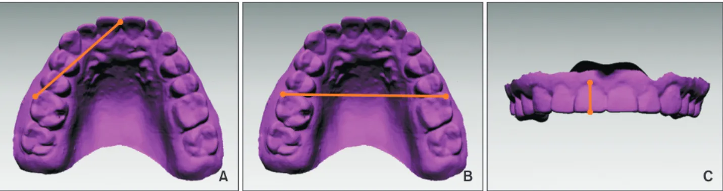
Using the image scanned immediately after impression taking as the reference image, all images taken according to the time elapse were reoriented to obtain a consistent 3D orientation using the surface registration function of the program. Three linear measurements were made on each digital model with the use of Rapidform 2006 software in three dimensions: anterior- posterior, transverse, and vertical. The anterior-posterior dimension was evaluated by measuring the incisor to molar from the mesiobuccal cusp tip of the upper right
A B C
Figure 1. The process of creating a digital dental model using a cone-beam computed tomography-scanned alginate impression. A, Stereolithography file was imported into the Rapidform 2006 program (Inus, Seoul, Korea). B, The negative of the impression was converted into the positive form. C, Excessive area over the impression tray was trimmed to complete fabrication of the digital dental model.
A B C
Figure 2. Linear measurements made on each digital model. A, Incisor to molar; B, intermolar width; C, incisor height.
first molar to the maxillary midline. The transverse dimension was measured using the intermolar width, the line between the mesiobuccal cusp tip of the upper right first molar and the same point on the upper left first molar. The vertical dimension was evaluated using the incisor height, which was measured from the incisal edge at the midline of the maxillary right central incisor to the gingival margin (Figure 2).
Statistical analysis
In order to assess the measurement errors, 20 images were selected randomly, and the measurements were obtained twice at an interval of two weeks by an examiner. The method errors of double registration of all the measurements were calculated using the Dahlberg’s formula.
12The results were as follows: 0.29 mm for the incisor to molar, 0.29 mm for the intermolar width, and 0.27 mm for the incisor height. In addition, intraclass correlation coefficients (ICC) were evaluated using a two- way mixed-effects model with absolute agreement to evaluate the reliability of intra-examiner measurements.
The ICC values for the 3 linear measurements according to the time elapse were 85% to 95%. The Shapiro-Wilks test for normality showed that all measurements were normally distributed.
The means and standard deviations of the actual measurements were calculated for each material and for each time period. Pair-wise comparisons were carried out using the t-test to identify differences between the control and each digital model according to elapsed time. The means and standard deviations of changes in measurements according to the time elapse were calculated. The changes within the measurement error (0.29 mm for the incisor to molar, 0.29 mm for the intermolar width, and 0.27 mm for the incisor height) were regarded as clinically acceptable in this study. The changes within the measurement error were assessed to evaluate the time point at which clinically relevant differences began to appear. Differences in the measurement change between the materials were also evaluated within the setting time. All statistical analyses were carried out using the IBM SPSS Statistics software (version 20.0; IBM Co., Armonk, NY, USA).
RESULTS
The means and standard deviations of the measurements for each material and each elapsed time are presented in Table 1. All measurements showed a decreasing tendency with an increase in the elapsed time after the impression. The comparison of each image obtained at different elapsed times with the control showed no statistically significant differences at the time point of 1 hour. Statistically significant differences began to appear
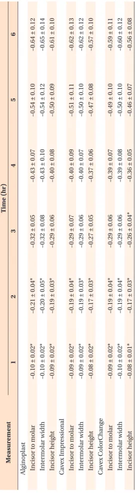
Table 1. Measur ement data (unit: mm) and comparisons of each image obtained at differ ent elapsed times with the contr ol M eas ur em en t Con tr ol
†Tim e (hr) 1 2 3 4 5 6 Al ginopl as t I ncis or t o mol ar 38.53 ± 1.55 38.43 ± 1.54 38.32 ± 1.53* 38.20 ± 1.52* 38.10 ± 1.52* 37.99 ± 1.51* 37.89 ± 1.50* I n ter mol ar w idth 53.56 ± 1.88 53.46 ± 1.88 53.36 ± 1.88* 53.24 ± 1.88* 53.13 ± 1.87* 53.02 ± 1.86* 52.90 ± 1.86* I ncis or hei gh t 9.20 ± 0.57 9.11 ± 0.56 9.01 ± 0.57* 8.90 ± 0.57* 8.80 ± 0.57* 8.69 ± 0.57* 8.59 ± 0.56* C av ex Im pr es sion al I ncis or t o mol ar 38.53 ± 1.65 38.45 ± 1.66 38.35 ± 1.66* 38.24 ± 1.66* 38.14 ± 1.67* 38.03 ± 1.68* 37.92 ± 1.68* I n ter mol ar w idth 53.58 ± 1.91 53.50 ± 1.91 53.39 ± 1.92* 53.29 ± 1.93* 53.18 ± 1.93* 53.08 ± 1.94* 52.97 ± 1.94* I ncis or hei gh t 9.21 ± 0.66 9.13 ± 0.66 9.04 ± 0.67* 8.94 ± 0.68* 8.84 ± 0.69* 8.74 ± 0.69* 8.64 ± 0.70* C av ex C olorC h an ge I ncis or t o mol ar 38.33 ± 1.65 38.24 ± 1.65 38.14 ± 1.66* 38.04 ± 1.66* 37.94 ± 1.67* 37.84 ± 1.69* 37.75 ± 1.69* I n ter mol ar w idth 53.57 ± 1.90 53.48 ± 1.90 53.38 ± 1.90* 53.29 ± 1.90* 53.18 ± 1.90* 53.08 ± 1.90* 52.97 ± 1.90* I ncis or hei gh t 9.15 ± 0.65 9.06 ± 0.65 8.98 ± 0.64* 8.88 ± 0.64* 8.79 ± 0.63* 8.69 ± 0.62* 8.59 ± 0.62* V alues ar e pr es en te d as me an±s tand ar d de vi ation. Al ginopl as t: H er aeus K ulz er Gm bH, H an au, G er m an y; C av ex Im pr es sion al and C av ex C olorC h an ge: C av ex H oll and B V, H aar lem , the N ether lands . *T he r es ults of the p air ed t-t es t ( p < 0.05).
†C on tr ol im ag e w as obtaine d fr om the s can imme di at el y aft er the im pr es sion w as tak en.
Table 2. Time-r elated changes in the measur ements (unit: mm) M eas ur em en t Tim e (hr) 1 2 3 4 5 6 Al ginopl as t I ncis or t o mol ar –0.10 ± 0.02* –0.21 ± 0.04* –0.32 ± 0.05 –0.43 ± 0.07 –0.54 ± 0.10 –0.64 ± 0.12 I n ter mol ar w idth –0.10 ± 0.02* –0.20 ± 0.05* –0.32 ± 0.08 –0.43 ± 0.10 –0.54 ± 0.12 –0.65 ± 0.14 I ncis or hei gh t –0.09 ± 0.02* –0.19 ± 0.03* –0.29 ± 0.06 –0.40 ± 0.08 –0.50 ± 0.09 –0.61 ± 0.10 C av ex Im pr es sion al I ncis or t o mol ar –0.09 ± 0.02* –0.19 ± 0.04* –0.29 ± 0.07 –0.40 ± 0.09 –0.51 ± 0.11 –0.62 ± 0.13 I n ter mol ar w idth –0.09 ± 0.02* –0.19 ± 0.03* –0.29 ± 0.06 –0.40 ± 0.07 –0.50 ± 0.10 –0.62 ± 0.12 I ncis or hei gh t –0.08 ± 0.02* –0.17 ± 0.03* –0.27 ± 0.05 –0.37 ± 0.06 –0.47 ± 0.08 –0.57 ± 0.10 C av ex C olorC h an ge I ncis or t o mol ar –0.09 ± 0.02* –0.19 ± 0.04* –0.29 ± 0.06 –0.39 ± 0.07 –0.49 ± 0.10 –0.59 ± 0.11 I n ter mol ar w idth –0.10 ± 0.02* –0.19 ± 0.04* –0.29 ± 0.06 –0.39 ± 0.08 –0.50 ± 0.10 –0.60 ± 0.12 I ncis or hei gh t –0.08 ± 0.01* –0.17 ± 0.03* –0.26 ± 0.04* –0.36 ± 0.05 –0.46 ± 0.07 –0.56 ± 0.08 V alues ar e pr es en te d as me an ± s tand ar d de vi ation. D ata sho w the differ ence b et w een the me as ur emen ts tak en imme di at el y aft er the im pr es sion and a t e ac h el aps ed time . *T he c h an ges w ithin the me as ur emen t er ror (0.29 mm for the incis or t o mol ar and the in ter mol ar w idth , and 0.27 mm for the incis or hei gh t).
1
6 Hour
1 2 3 4 5
0 0
B
0.2
0.4
0.6
0.8
Alginoplast Cavex Impressional Cavex ColorChange
1
6 Hour
1 2 3 4 5
0 0
C
0.2
0.4
0.6
0.8
Alginoplast Cavex Impressional Cavex ColorChange
Intermolarwidth(mm)Incisorheight(mm)Incisortomolar(mm)
1
6 Hour
1 2 3 4 5
0 0
A
0.2
0.4
0.6
0.8
Alginoplast Cavex Impressional Cavex ColorChange