Progress in Superconductivity and Cryogenics
Vol.15, No.4, (2013), pp.34~38 http://dx.doi.org/10.9714/psac.2013.15.4.034
```
1. INTRODUCTION
Due to the increase of electric consumption nowadays, the size of ground and short circuit faults also increases and the volume of fault current exceeds the cutoff capacity of a circuit breaker. This kind of fault current leads to big accidents such as major power outages and damages of human and property. In order to resolve these problems, several solutions are performed such as separation of bus line, series reactor etc, but these are creating another problems of stability of power system, trustfulness, electrical quality etc. In order to resolve these all problems, an SFCL was suggested and still it’s studied continuously [1-2]. Since superconducting element keeps nearly zero resistance, there was no loss. loses the characteristic of its superconductivity, we call it as quench. Quench creates impedance. And this impedance limited to fault current effectively. Also, when the fault current flows, superconducting element was quenched and it automatically limits within 8ms[3]. It minimizes the spread of damage by reducing the effect for peripherals and comes back to superconducting states within 0.5sec after limiting fault current as well. In order to apply new circuit breaker in current power system, economic losses caused by replace of existing equipment. But an SFCL has many advantages considering that the overall principle and structure are simple, current equipments are applicable without any change. Our research team drew up the plan of commercializing SFCL by combination with a transformer.
While the existing system has been taking all the
burdens of fault current by connecting an SFCL into the third-line. In contrast, an SFCL was connect to neutral line.
So the SFCL will not have any loss in the operations and it was allowed to limit only the initial fault current. In this case, the power burden of a superconducting element was reduced, we can create economic benefits by expanding the cycles exchanging of superconducting element[4-9].
In this paper, we analyzed the characteristics by turn-ratio in the three-phase transformer which applied an SFCL to the neutral line of a transformer when the line-to-ground fault happens. So we want to secure reliability of SFCL.
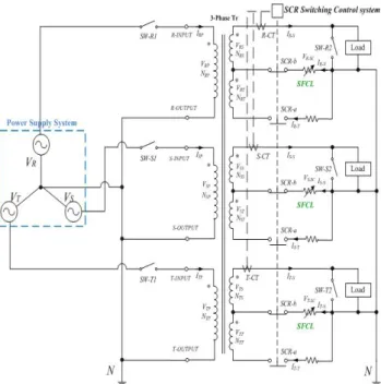
2. CIRCUIT DIAGRAM AND CONNECTION Fig. 1 shows the condition circuit diagram which combined SFCLs to the neutral line of three-phase transformer. The transformer has Y-type connection and applied voltage was 240V. A single line-to-ground fault was happened. YBCO thin film of 2inch diameter was used for superconducting element and 10Ω resistance was used for current limiting element of normal conductor.
In normal condition, the current was supposed to be supplied through operating route as Fig. 2 (a). When the fault current was happened by using fault switch SW-R2, the SFCL on the neutral line was quenched with impedance and finally limited the initial fault current. At the same time, the Current Transformer(CT) located on each phase and detected the fault current and activated the SCR on each phase. Operating rote was changed by the turn-on & turn-off of each b contact & a contact by the
Characteristics of the SFCL by turn-ratio of three-phase transformer
I. S. Jeong, H. S. Choi*, and B. I. Jung Chosun University,GwangJu, Korea
(Received 18 November 2013; revised or reviewed 19 December 2013; accepted 20 December 2013)
Abstract
According to the increase of electric consumption nowadays, power system becomes complicated. Due to this, the size of single line-to-ground fault from power system also increases to have many problems. In order to resolve these problems effectively, an Superconducting Fault Current Limiter(SFCL) was proposed and continuous study has been done. In this paper, an SFCL was combined to the neutral line of a transformer. An superconductivity has the characteristics of zero resistance below critical temperature. because of this, SFCL has nearly zero resistance. so we connecting SFCL to neutral line will not only have any loss in the normal operation but also have the less burden of electric power because of only limiting the initial fault current. We analyzed the characteristics of current, voltage according to the changes of turn ratio of 3 phase system in case of combinations of an SFCL to the neutral line. It was confirmed that the limiting rate of initial fault current by the increase of turn ratio was reduced.
Keywords : SFCL, Turn-ratio, Current limitation, Line-to-ground
* Corresponding author: [email protected]
I. S. Jeong, H. S. Choi, and B. I. Jung
Fig. 1. Circuit diagram of SFCL applied on three-phase transformer.
(a)
(b)
Fig. 2. Operating route in (a) Normal condition, (b) Fault condition.
SCR switching control system, as shown in Fig. 2 (b).
Fault current flowed into normal conductivity limiter by changed line and was limited accordingly. Table I was characteristic of SFCL and Table Ⅱshows the experimental conditions.
TABLE I CHARACTERISTICS OF SFCL.
Parameter Value
Diameter (inch) 2
Strip width (mm) 2
Length (mm) 540
Thickness of YBCO (μm) 0.3
Thickness of Au 0.1~0.2
TABLEII EXPERIMENTAL CONDITIONS.
Parameter Value
Voltage (V) 240
Fault current Line-to-ground
Limiting device Superconductor, Normal conductor
Fault cycle (cycle) 5
3. EXPERIMENT AND DISCUSSION 3.1. Np:NS:NT=3:2:1
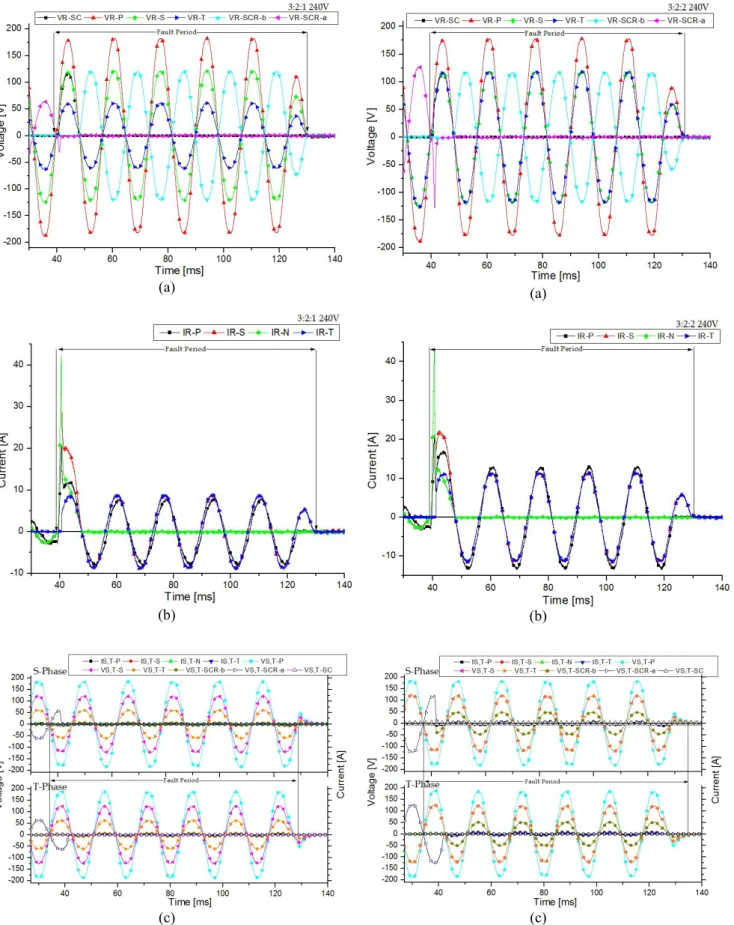
Fig. 3 shows the voltage and current characteristics of the turn ratio was NP:NS:NT=3:2:1 when occured a single line-to-ground fault. Fig. 3 (a) shows the voltage characteristics of R-phase which is fault phase. The voltages of primary, secondary and third winding were reduced to 177, 117, 59V. because the turn ratio was 3:2:1.
Voltage of SCR-b switch was not occurred before the fault.
On the other hand, voltage of SCR-a switch had 63V before the fault, but it was not have voltage after the fault.
And SCR-a switch started to activate after 1ms from SCR-b switch activation. In case of SFCL, the voltage was happened after the fault due to the resistance while it was not found before. But after 8 ms, the line power became open by the activation of the SCR and no more voltage was happened.
Fig. 3 (b) shows the current characteristics on R phase which is fault phase. Right after the fault, the fault current was about 21A limited by SFCL, and it was reduced to 7A after 8ms from the fault instant. After that, fault current to flow into normal conductivity limiter by the SCR activation. In case of an SFCL, the current of 2A flowed before the fault, but after that, current of 42A flowed. In 8ms, line was opened by an SCR and no more current was confirmed.
Fig. 3 (c) shows voltage and current of S and T phases without any fault. In spite of no fault, since an SCR was activated simultaneously with R phase, there were no particular things except voltage of band a switches.
3.2. Np:NS:NT=3:2:2
Fig. 4 shows the voltage and current characteristics of a transformer when the turn ratio was NP:NS:NT = 3:2:2 in case of a single line-to-ground fault. Fig. 4 (a) is the graph showing the voltage characteristics on R phase which is fault phase. Voltages of primary, secondary and third windings showed 184, 122, 122V. Third winding’s turn ratio was increased. And SCR-a switch’s voltage which was connected to third winding was also increased to 127V.
But it could only act with SCR-b switch at the same time
Characteristics of the SFCL by turn-ratio of three-phase transformer
(a)
(b)
(c)
Fig. 3. Characteristics of voltage and current when winding ratio was NP:NS:NT=3:2:1, (a) Voltage of R-Phase during the fault, (b) Current of R-phase during the fault, (c) Voltage and current of S and T phase on normal operation.
(a)
(b)
(c)
Fig. 4. NP:NS:NT=3:2:2, Characteristics of (a) voltage (b) current on the fault R-phase in case of a single line-to-ground fault, (c) voltage and current on the normal S.T phases.
I. S. Jeong, H. S. Choi, and B. I. Jung
(a)
(b)
(c)
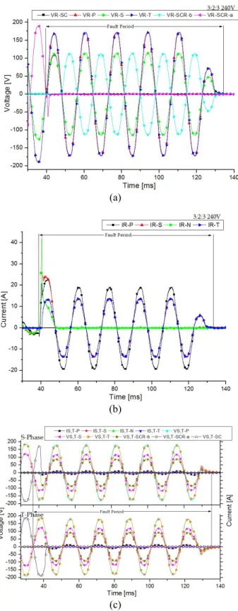
Fig. 5. NP:NS:NT=3:2:3, Characteristics of (a) voltage (b) current on the fault R-phase in case of a single line-to-ground fault, (c) voltage and current on the normal S.T phases.
after 4ms. An SFCL brought the voltage right after the fault, but in 8ms, power line was changed and no more voltage was detected.
Fig. 4 (b) was the graph of characteristics of current in the transformer when the turn ratio was 3:2:2. The value of
fault current which was limited by SFCL 20A. After this, 12A of fault current flowed into normal conductor limiter and it was limited by changed line.
Fig. 4 (c) shows voltage and current characteristics of T phases when the turn ratio was 3:2:2. There were no particular things except SCR contact actions.
3.3. Np:NS:NT=3:2:3
Fig. 5 shows the characteristics of voltage and current in the turn ratio is NP:NS:NT = 3:2:3. Fig. 5(a) was the graph of voltage. SCR-a voltage were increased to 188, 168V. At the time of the fault, SCR-b, switch was activated, after 3ms SCR-a switch was.
Fig. 5 (b) shows current characteristics of a transformer.
Right after the fault, fault current was limited to 20A by an SFCL and 2A was more reduced in 8ms. After this, by the change of the SCR switch, about 18A of fault current flowed into normal conducting limiter and was limited.
Fig. 5 (c) was the graph of voltage and current characteristics on S, T phases which are the normal phases, there was no particular things except SCR’s, switch actions.
By this experiment, We found that the transformer which was combined with an SFCL in third winding had no differences in limiting the fault current, but the combination of an SFCL in second winding limited initial fault current by 20A and more 13, 8, 2A were additionally limited while the SCR switch action was being made. After that, 7, 12, 18A of fault currents flowed into normal conducting limiter and were limited efficiently. In case SFCL was combined with secondary phase, since it only limits the initial fault current, not takes all the fault currents, it has an effect on reducing the burden of an SFCL and also preventing bad influences by sudden flows of fault current.
4. CONCLUSION
In this paper, we has applied SFCL to the neutral line of a transformer and analyzed the characteristics of voltage and current according to the change of turn ratio. Turn ratio has provided the change of NP:NS:NT=3:2:1, 3:2:2, 3:2:3. It was set up as a single line-to-ground fault. The voltage of 240V was applied. After the fault the SFCL limited fault current as 20A. But the value of an SFCL’s limitable fault current in 8ms was reducing by the decrease of turn ratio.
By the increase of turn ratio, the voltage on the switching spot of SCR-a was increased and its switching action was made after the SCR-b switching action. In the mechanical contact point, when the voltage increases, arc couldn’t be discharged and maintained and the switching action was delayed. Therefore, proper selection of SCR capacity should be accompanied according to the increase of the voltages. The transformer which we suggested the combination of an SFCL in third winding brought no differences in terms of fault current comparing with the combination of an SFCL in secondary winding. But in case of the combination with secondary winding, since it only limits the fault current, it was considered that it will provide economical profits because it reduces electric burden and expands the exchange period of an SFCL.
Characteristics of the SFCL by turn-ratio of three-phase transformer
ACKNOWLEDGMENT
This research was financially supported by the Ministry of Education, Science Technology (MEST) and National Research Foundation of Korea(NRF) through the Human Resource Training Project for Regional Innovation (No. N RF-2013H1B8A2032246).
REFERENCES
[1] H. S. Choi, O. B. Hyun, H. R. Kim, K. B. Park, "Switching properties of hybrid type superconducting fault current limiter using YBCO stripes" IEEE Trans. Appl. Superconduct, vol. 12, pp. 1833 - 1838, 2002.
[2] J. S. Kim, S. H. Lim, J. C. Kim, "Comparative Analysis on Current Limiting Characteristics of Hybrid Superconducting Fault Current Limiters (SFCL) with First Half Cycle Limiting and Non-Limiting Operations," JEET. vol. 7, no. 5, pp. 653-806, 2012.
[3] Yong-Sun Cho, Hyo-Sang Choi, Sung-Pil Go,"Operational Characteristics of Transformer-Type SFCL with or without Neutral Line between the Secondary windings and Superconducting units", Trans. KIEE. Vol. 60, No. 6, pp. 1268~1273, 2011.
[4] R. Kreutz, J. Bock, F. Breuer, K. P. Juengst, M. Kleimaier, H.-U.
Klein, D. Krischel, M. Noe, R. Steingass, and K. H. Weck, "System technology and test of curl 10, a 10 kV, 10 MVA resistive high-Tc superconducting fault current limiter," IEEE Trans. on Appl.
Superconduct., vol. 15, pp. 1961-1964, 2005.
[5] M.H.Kim, J.S.Kim, I.K.You, S.H.Lim, J.C.Kim, "A study on Practical Impedance of Superconducting Fault Current Limiter on Bus Tie in a Power Distribution System", JEET, vol.1, no.1, pp.
1-122, 2011.
[6] A. C. Lapthorn, I. Chew, W. G. enright, and P. S. Bodger, "HTS transformer: construction details, test results, and noted failure mechanisms", IEEE Trans. Power Delivery, vol. 26, no.1, 394-399, 2011.
[7] B. W. Lee, K. B. Park, J. Sim, I. S. Oh, H. G. Lee, H. R. Kim, O. B.
Hyun, “Design and Experiments of Novel Hybrid Type Superconducting Fault Current Limiters," IEEE Trans. Appl.
Supercond., vol. 18, no. 2, pp. 624-627, 2008.
[8] Y. Yorozu, M. Hirano, K. Oka, and Y. Tagawa, "Electron spectroscopy studies on magneto-optical media and plastic substrate interface," IEEE Transl. J. Magn. Jpn., vol. 2, pp. 740-741, 1987 [Dig. 9th Annual Conf. Magn. Jpn., pp. 301, 1982].
[9] M. Young, The Technical Writer's Handbook, Mill Valley, CA:
University Science, 1989.