Progress in Superconductivity and Cryogenics
Vol.15, No.4, (2013), pp.30~33 http://dx.doi.org/10.9714/psac.2013.15.4.030
```
1. INTRODUCTION
At present, due to the increased domestic electric power demand the large electric power equipments are growing.
As a result, in case of the electric power system, fault current increases, and in the end, exceeds the strength of the break of the existing circuit breaker [1-3]. At location where exceeds breaking capacity of the circuit breaker, repair and replacement of circuit breaker is to be done, however, in the future, to prepare for the increased electric power demand causes many economic and technical problems. Superconducting Fault Current Limiter (SFCL) was designed to solve these problems. When you apply the SFCL to the electric power system, during normal operation the SFCL is operated without affecting the surrounding fixtures and electric line, however, when the fault current exceeds critical current value of a superconductor, the SFCL would be in quench and operated in high impedance, and limit the fault current size quickly. Limiting fault current less than breaking capacity, the SFCL makes existing circuit breaker to be operated reliably without replacement or increasing capacity of existing circuit breaker, and make electric power system to be effectively protected from faults [4-5].
In this paper, simple resistive type SFCL among various types of SFCL was applied to three-phase transformer.
The proposed structure is that SFCL is connected to the third winding of the transformer. During normal operation the SFCL is operated as normal transformer, however in case of electric power system fault, SFCL connected to third winding limits fault current size.
2. EXPERIMENTAL METHODS AND CONFIGURATION
Fig. 1 is a circuit diagram of this experiment in which a SFCL is connected to third winding transformer. During normal operation a transformer provides electric power based on the voltage ratio (V
P/V
S) to the load (R).
However in case of electric power system fault accident, fault current flows through a SFCL by switching operation of the SCR, the fault current is limited by quench operation of the SFCL. Each CT connected to the phase detects the fault current.
SW2 of Fig. 1 is a switch for mock accident, SCR-a, b contacts are for bypass circuit of fault current. Load resistance (R) and normal impedance (Z
L) of electric line were set as 50, 1 [Ω] respectively. Also R
SCused YBa
2Cu
3O
7(YBCO) thin film as current-limiting element connected to third winding. Applied SFCL has superconducting characteristics in liquid nitrogen bath.
A transformer used in this experiment was step-down transformer of which primary, secondary voltage ratio was
Fig. 1. Experimental circuit diagram of a SFCL.
Operation characteristics of SFCLs combined with a transformer in three-phase power system
B. I. Jung* and H. S. Choi Chosun University, Gwangju, Korea
(Received 1 November 2013; revised or reviewed 25 November 2013; accepted 26 November 2013)
Abstract
The studies of superconducting fault current limiter (SFCL) for reduction of the fault current are actively underway in the worldwide. In this paper, we analyzed the characteristics of a new type SFCL using the conventional transformer and superconducting elements combined mutually. The secondary and third windings of this SFCL were connected the load and the superconducting element, respectively. The electric power was provided to load connected to secondary windings of the transformer in normal state of power system. On the other hand, when the fault occurred in power system, the fault current was limited by closing the line of third winding of the transformer. At this time, the ripple phenomenon of the fault was minimized by opening the fault line in secondary winding of a transformer in power system. The sensing of the fault state was performed by the CT(current transformer) and then turn-on and turn-off switching behavior of the SFCL was performed by the SCR(silicon-controlled rectifier). As a result, the proposed SFCL limited the fault current within a half-cycle efficiently. We confirmed that the fault current limitation rate was changed according to the winding ratio of a transformer.
Keywords : Superconducting fault current limiter (SFCL), current transformer (CT), silicon controlled rectifier (SCR), transformer
* Corresponding author: [email protected]
B. I. Jung and H. S. Choi
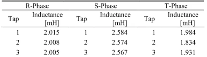
TABLEI
PARAMETER OF THREE-PHASE TRANSFORMER.
R-Phase S-Phase T-Phase
Tap Inductance
[mH] Tap Inductance
[mH] Tap Inductance [mH]
1 2.015 1 2.584 1 1.984
2 2.008 2 2.574 2 1.834
3 2.005 3 2.567 3 1.931
3:2. Turn’s ratio of third winding connected with the SFCL was changed with 1, 2, and 3 and we compared characteristics of each operation. At this time applied voltage (V
m) size was set as 240V. Table 1 is the inductance value of three-phase transformer used in this experiment.
3. RESULTS AND DISCUSSION 3.1. Each Phase Current Curves and SCR switching operation
Three-phase transmission line was configured based on experimental circuit diagram of fig. 1 for experimentation.
In order to compare and analyze the effects of each phase of a transformer connected to the SFCL we made a triple line-to-line fault and experimented. Fig. 2 show limited fault current in case of power system transient state, that current size is neutral line current (I
N) which flows between primary, secondary, and third current and secondary, third current in a transformer. At this time, by analyzing SCR contact voltage, we could determine the presence or absence of switching operation. Fault of electric line was developed on the basis of the phase R. Fig.
2(a-1, 2, 3) is characteristics curves of R phase which show winding ratio change of third winding in transformer connected to the SFCL. Before power system fault, the current of same size flew at secondary current (I
SC) of a transformer and electric current of neutral line (I
N), primary ratio current which was inversely proportional to the winding ratio flows. After the fault, due to the SCR switching operation neutral line current (I
N) did not flow, electric current bypassed to third winding, size of this current was same as size of secondary current, but directions were reversed. During half-period of fault, limited fault current of primary coil is 43.02A, 70.98A.
Two acute parts exists. This is the moment that SCR b contact is open. This phenomenon is due to instability of flow of electric current. After the fault, due to SCR switching operation the electric current (I
N) of neutral line did not flow, electric current bypassed to third winding, size of this electric current was same as size of secondary electric current, but directions were reversed. After the accident, the size of secondary electric current 42.88A in a transformer was same as size of third current, but directions of electric current were reversed. After half-period of accident, due to electric current limit operation of the SFCL size of current was about 5~6A. In accordance with increasing of third winding ratio of transformer, primary electric current size tended to increase, secondary and third current size tended to decrease. This was the phenomenon occurred due to switching operation of SCR, the structure of secondary and third coil became additive winding, winding became bigger than primary.
180 190 200 210 220 230 240 250
-40 -20 0 20 40 60 80
Fault point I-1st line I-2nd line I-3rd line I-Neutral line
Current[A]
Time[msec]
180 190 200 210 220 230 240 250
-200 -150 -100-50500 100 150 200 (a-1)
SCR-b contact : open
SCR-a contact : open R-phase(Trun ratio-3:2:1) V(SCR:b-contact) V(SCR:a-contact)
Voltage[V]
180 190 200 210 220 230 240 250
-40 -20 0 20 40 60 80
Fault point I-1st line I-2nd line I-3rd line I-Neutral line
Current[A]
Time[msec]
180 190 200 210 220 230 240 250
-200 -150 -100100150200-50500 (a-2)
R-phase(Trun ratio-3:2:2) V(SCR:b-contact) V(SCR:a-contact)
Voltage[V]
180 190 200 210 220 230 240 250
-40 -20 0 20 40 60
80 Fault point I-1st line I-2nd line I-3rd line I-Neutral line
Current[A]
Time[msec]
180 190 200 210 220 230 240 250
-200 -150-100100150200-50500 (a-3)
R-phase(Trun ratio-3:2:3) V(SCR:b-contact) V(SCR:a-contact)
Voltage[V]
Fig. 2. Each phase current and SCR switching operation curves. (a) R-phase.
Fig. 3 shows fault current and SCR operation characteristics of phase S under the same condition as the fault of Fig. 2. Fig. 3(b-1, 2, 3) implies that after power system fault during half-period, in case of phase S, close operation of SCR-a contact is on, but open operation of SCR-b contact is off. So this third fault current that should bypass in third flows still in neutral line. Accordingly quench operation of the SFCL was delayed.
Fig. 3(b-1) shows that in neutral line over 215A current
flows, in third 30A electric current flows. This experiment
mocked the accident which used phase R fault angle 0
degree. Consequently in case of phase S which 120 degree
precedes, open operation of the SCR-b contact was on
while electric current flows. Delay of the SCR is a result
caused by surge voltage that occurred at this time.
Operation characteristics of SFCLs combined with a transformer in three-phase power system
180 190 200 210 220 230 240 250
-250 -200 -150 -100 -50 0 50
I-1st line I-2nd line I-3rd line I-Neutral line
Current[A]
Time[msec]
180 190 200 210 220 230 240 250
-150 -100 -50 0 50 100
150 (b-1) V(SCR:b-contact)
V(SCR:a-contact) S-phase(Trun ratio-3:2:1)
Voltage[V]
180 190 200 210 220 230 240 250
-250 -200 -150 -100 -50 0 50
I-1st line I-2nd line I-3rd line I-Neutral line
Current[A]
Time[msec]
180 190 200 210 220 230 240 250
-150 -100 -50 0 50 100
150 (b-2) S-phase(Trun ratio-3:2:2) V(SCR:b-contact)
V(SCR:a-contact)
Voltage[V]
180 190 200 210 220 230 240 250
-250 -200 -150 -100 -50 0 50
I-1st line I-2nd line I-3rd line I-Neutral line
Current[A]
Time[msec]
180 190 200 210 220 230 240 250
-200-150 -100100150200-50500
(b-3)
S-phase(Trun ratio-3:2:3) V(SCR:b-contact) V(SCR:a-contact)
Voltage[V]
Fig. 3. Continued from fig. 2 (b) S-phase.
In case of phase S, as same as phase R, in accordance with increasing of third winding ratio in a transformer, primary electric current size tended to increase, secondary and third current size tended to decrease.
In case of phase S, due to problem of switching operation of SCR after half-period operation was on, however after half-period, stable limit operation is executed.
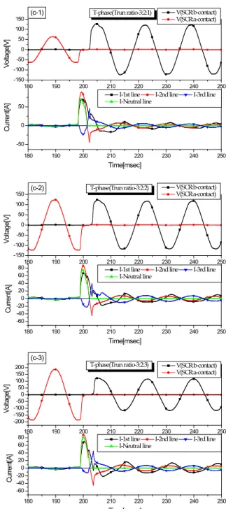
Fig. 4 shows current curve of phase T and operation of SCR. In case of phase T, as same as phase S, after fault the SCR switching operation was not on. In this case, phase T accident occurred at the point where -120 degree differed from phase R accident point, delay of SCR switching operation was caused by surge voltage that occurred in open operation. In case of phase T, after a lapse of time of
180 190 200 210 220 230 240 250
-50 0 50
I-1st line I-2nd line I-3rd line I-Neutral line
Current[A]
Time[msec]
180 190 200 210 220 230 240 250
-150 -100 -50 0 50 100
150 (c-1) T-phase(Trun ratio-3:2:1) V(SCR:b-contact)
V(SCR:a-contact)
Voltage[V]
180 190 200 210 220 230 240 250
-60 -40
-20204060800 I-1st line I-2nd line I-3rd line I-Neutral line
Current[A]
Time[msec]
180 190 200 210 220 230 240 250
-150 -100 -50 0 50 100
150 (c-2) T-phase(Trun ratio-3:2:2) V(SCR:b-contact)
V(SCR:a-contact)
Voltage[V]
180 190 200 210 220 230 240 250
-60 -40
-20204060800 I-1st line I-2nd line I-3rd line I-Neutral line
Current[A]
Time[msec]
180 190 200 210 220 230 240 250
-200-150 -100100150200-50500
(c-3)
T-phase(Trun ratio-3:2:3) V(SCR:b-contact) V(SCR:a-contact)
Voltage[V]
Fig. 4. Continued from fig. 2 (c) T-phase.
approximately 4 msec from accident, switching operation of SCR was on, faster than phase S, electric current limit operation was executed.
3.2. Voltage Curves of a Superconducting Element Fig. 5 shows voltage of a superconducting element according to third winding ratio of a transformer.
Superconducting element tended to be degraded by
voltage rather than current, it was an important point to
take in applying the SFCL. We confirmed that as the turn’s
ratio of third coil increased, the voltage of the
superconducting element increased. This result will
contribute to minimize power burden of a superconducting
element when the SFCL is applied to other type of a
transformer (for step-up, voltage compensation, etc.).
B. I. Jung and H. S. Choi
180 190 200 210 220 230 240 250
-300 -200 -100 0 100 200 300 (a)
Trun ratio : 3 : 2 : 1
Voltage[V]
Time[msec]
V-SC : R-phase V-SC : S-phase V-SC : T-phase
180 190 200 210 220 230 240 250
-300 -200 -100 0 100 200 300 (b)
Trun ratio : 3 : 2 : 2
V-SC : R-phase V-SC : S-phase V-SC : T-phase
Voltage[V]
Time[msec]
180 190 200 210 220 230 240 250
-300 -200 -100 0 100 200 300 (c)
Trun ratio : 3 : 2 : 3
V-SC : R-phase V-SC : S-phase V-SC : T-phase
Voltage[V]
Time[msec]
Fig. 5. Voltage curves of a superconducting element. (a) Turn ratio : 3:2:1. (b) Turn ratio : 3:2:2. (c) Turn ratio : 3:2:3.
4. CONCLUSION
In this paper, we analyzed characteristics of application of the SFCL to three phase transformer using a power semiconductor switch. The SFCL of this structure maintained the function of transformer during normal operation of electric power system, in case of fault, using SCR, electric line bypassed to the SFCL and limited fault current. The SFCL theoretically operates without loss in the AC line. Actually, in accordance with the problem of manufacturing and the flow of electric current, loss is occurred with impedance over certain value. However the SFCL proposed in this paper, using switch (SCR) for electric power was always open to electric line, in case of
electric power system fault, connected to electric line, limited fault current. After triple line-to-line fault on the SFCL of proposed structure, we compared and analyzed electric current limit operation of each phase.
Due to fault occurred on phase R 0 degree, in case of phase S, T, at early stage of fault open operation of SCR-b contact was not on, so fault current limit operation was delayed. However, after half-period from fault, every phase limited stably fault current over 70~80%. For fault current limit ratio according to increase of third winding ratio in a transformer primary electric current size tended to increase, secondary and third current size tended to decrease. Voltage size transmitted to SFCL was increased in proportion to winding ratio.
ACKNOWLEDGMENT
This research was financially supported by the Ministry of Education (MOE) and National Research Foundation of Korea (NRF) through the Human Resource Training Project for Regional Innovation
(No. NRF-2013H1B8A2032246)
REFERENCES
[1] Hyo-Sang Choi, Byung-Ik Jung, and Yong-Sung Cho, "Transient Characteristics of a Flux-Coupling Type Superconducting Fault Current Limiter According to Winding Direction,” IEEE Trans.
Appl. Supercond., vol. 19, no. 3, pp. 1827-1830, 2009.
H. S. Choi, H. R. Kim, O. B. Hyun and S. J. Kim, “Quench properties of Y-Ba-Cu-O films after overpowering quenches,” IEEE Trans. Appl. Supercond., vol. 11, no. 2, pp.2418-2421, 2001.
[2] Jung-Hyeon Ryu, Ike-Sun Choi, and Kern-Joong Kim,
“Three-phase making test method for common type circuit breaker,”
Journal of Electrical Engineering & Technology, vol. 7, no. 5, pp.
778-783, 2012.
[3] Seun Ryul Lee, Jae-Young Yoon, Byeongmo Yang, Byoungjun Lee,
“Specifications of the 22.9 kV SFCL Considering Protection Systems in Korean Power Distribution System”, IEEE Trans. Appl.
Supercond., vol. 22, no. 3, pp. 5602404, 2012.
[4] Jin-Seok Kim, Sung-Hun Lim, and Jae-Chul Kim, “Comparative Analysis on current limiting characteristics of hybrid superconducting fault current limiters (SFCLs) with first half cycle limiting and non-limiting operation,” Journal of Electrical Engineering & Technology, vol. 7, no. 5, pp. 659-663, 2012.