• 검색 결과가 없습니다.

Analysis on operation characteristics and power burdens of the double quench trigger type SFCLs

N/A
N/A
Protected

Academic year: 2021

Share "Analysis on operation characteristics and power burdens of the double quench trigger type SFCLs"

Copied!
5
0
0

로드 중.... (전체 텍스트 보기)

전체 글

(1)

Vol.19, No.2, (2017), pp.33~37 https://doi.org/10.9714/psac.2017.19.2.033

```

1. INTRODUCTION

Recently, continuous society and industrial development have enlarged our power consumption and this increase of power consumption makes the fault current to be large. Due to increase of fault current, capacities of the installed protective equipment like circuit breaker can be exceeded and it is suggested that there are possibilities that the protective equipment can not interrupt correctly against the fault current. The interruption failures may cause the electrical devices to be out of order and the huge scale black out by cascading. So many solutions are studied to reduce fault current. But there are no certain solution for various reasons, like a financial problem, power losses, improvement of sag and etc. As a one of the effective solutions for reducing the fault current, superconducting fault current limiters (SFCLs) is paid attention [1-3].

As the SFCLs use a high temperature superconductor (HTSC), the SFCLs have zero impedance and no power loss in normal state [4, 5]. When fault current occurred, the SFCLs immediately turn to resistive material and play a role as a fault current limiter. This fault current limiting operation completes within one quarter period and this operating time is very fast comparing to other protective devices [5, 6].

There are various types SFCLs that has above characteristics like Hybrid type SFCL, transformer type SFCL, flux-lock type SFCL and so on. Each type SFCL has different configurations and characteristics. One of the various types SFCLs is the trigger type SFCL. The trigger type SFCL is researched to install in real power system

because it has advantages, such as simple configuration mechanically and effective operation [6-8].

In this paper, the operation characteristics and power burden of the trigger type SFCL was analyzed through the short circuit experiment when the SFCLs is applied to power systems. In addition, the double quench trigger type SFCL that uses two HTSCs unlike existing trigger type SFCL is proposed and analyzed.

2. PREPARATION FOR SHORT CIRCUIT TEST

2.1. Single / Double quench trigger type superconducting fault current limiter (SFCL)

Fig. 1 shows the superconducting fault current limiters (SFCLs) configurations that are used in this paper. Fig. 1(a) is a basic trigger type SFCL which is commonly used to prove in ability field test of the SFCLs. The trigger type SFCL is composed of switch (SW), a high temperature superconductor ( 𝐻𝑇𝑆𝐶 1 ) module and resistance (CLR).

The normal current flows through the 𝐻𝑇𝑆𝐶 1 (𝑖 𝑆𝐶1 ) before a fault occurred. But when the current through the 𝐻𝑇𝑆𝐶 1 is exceeded over the critical current the fault occurrence, the 𝐻𝑇𝑆𝐶 1 is changed from superconductive state to non-superconductive state (quench operation). According for 𝐻𝑇𝑆𝐶 1 to take voltage over the 5 [V] (because the voltage caused by quench is generally greater than 5[V] in this paper), the switch (SW) that is sensing the voltage of 𝐻𝑇𝑆𝐶 1 (𝑣 𝑆𝐶1 ) from the PT is opened and the fault current flow through the CLR ( 𝑖 𝐶𝐿𝑅 ). Described operation of single quench SFCL is shown in Fig. 3(a).

In this paper, the first SFCL in Fig. 1(a) will be called as

‘the single quench trigger type SFCL’ to compare with a second SFCL called ‘the double quench trigger type SFCL’

in Fig. 1(b) .

Analysis on operation characteristics and power burdens of the double quench trigger type SFCLs

Seung-Taek Lim a , Sung-Hun Lim a , and Tae-Hee Han b,*

a Department of Electrical Engineering, Soongsil University, Seoul 156-743, Republic of Korea

b Department of Aero Materials Engineering, Jungwon University, Chungbuk 367-805, Republic of Korea

(Received 22 February 2017; revised or reviewed 13 June 2017; accepted 14 June 2017)

Abstract

To protect the power systems from fault current, the rated protective equipment should be installed. However growth of power system scale and concentration of loads caused the large fault current in power transmission system and distribution system. The capacities of installed protective equipment have been exceeded the due to increase of fault current. This increase is not temporary phenomenon but will be steadily as long as the industry develops. The power system operator need a counter-measurement for safety, so superconducting fault current limiter (SFCL) has been received attention as effective solutions to reduce the fault current.

For the above reasons various type SFCLs have been studied recently. In this paper, operation characteristics and power burden of trigger type SFCL is studied. The trigger type SFCL has been used for real system research in many countries. Another trigger type SFCL (double quench trigger type SFCL) is also studied. For this paper, short circuit test is performed.

Keywords: Double quench, Operation characteristics, Power burden, Superconducting fault current limiter (SFCL), Trigger type SFCL

* Corresponding author : [email protected]

(2)

Fig. 1. Superconducting Fault Current Limiter (SFCL) configurations used in short circuit test.

(a) Single quench trigger type SFCL (b) Double quench trigger type SFCL

Fig. 1(b) is a double quench trigger type SFCL which is modification of the single quench trigger type SFCL. The double quench trigger type SFCL is composed of a switch (SW), two HTSCs ( 𝐻𝑇𝑆𝐶 1 , 𝐻𝑇𝑆𝐶 2 ) and resistances (CLRs). A difference with the single quench trigger type SFCL is that the double quench trigger type SFCL has one more HTSC (𝐻𝑇𝑆𝐶 2 ). Operation of the SFCL is similar to single quench trigger type SFCL. The normal current flows through the 𝐻𝑇𝑆𝐶 1 (𝑖 𝑆𝐶1 ) before a fault occurred. But when current through the 𝐻𝑇𝑆𝐶 1 is exceeded over the critical current by the fault occurrence, the 𝐻𝑇𝑆𝐶 1 changes to resistance material and limits the fault current firstly and the switch is opened because of 𝐻𝑇𝑆𝐶 1 ’s voltage. Then, the fault current flows through the 𝐻𝑇𝑆𝐶 2 (𝑖 𝑆𝐶2 ) and 𝐶𝐿𝑅 2

(𝑖 𝐶𝐿𝑅 2 ). If the 𝑖 𝑆𝐶2 is still so large that the 𝐻𝑇𝑆𝐶 2 quenches, the 𝐻𝑇𝑆𝐶 2 changes to resistance material and limits the fault current secondly. Then, the fault current flows through the two paths, the 𝐶𝐿𝑅 2 (𝑖 𝐶𝐿𝑅 2 ) and 𝐻𝑇𝑆𝐶 2 (𝑖 𝑆𝐶2 ).

The characteristics of the double quench trigger type SFCL is that it has twice fault current limiting operation according to scale of fault current. Described operation of double quench trigger type SFCL is shown in Fig. 3(b).

In operation, the 𝐻𝑇𝑆𝐶 1 plays two roles. The first role is that the 𝐻𝑇𝑆𝐶 1 reduces the initial fault current within a quarter period and the second role is that it detects the fault by turning to non-superconductive material. Although power electronics can be used for both two roles, HTSCs is more effective on the side of operation speed, install space and environmental machines [6, 7].

Specifications of the SFCLs used in short circuit test are filled in Table 1 [9].

2.2. Experimental short circuit

Fig. 2 is configuration for the short circuit test. The experimental circuit was consists of AC power supply (𝐸 𝑖𝑛 ), circuit breaker (CB), line impedance (𝑅 1 , 𝑋 1 ), load impedance ( 𝑅 𝐿 ) two switches ( 𝑆𝑊 1 , 𝑆𝑊 2 ) and superconducting fault current limiter (SFCL). The AC power supply supplied 360 [V] by closing the 𝑆𝑊 1 . The circuit breaker that is operated by overcurrent relay was installed at the front of SFCL and had two reclose operations. Single line ground fault occurred permanently at 0.6 [s] and the short circuit test was performed at fault angle 0ᵒ which generates the most significant transient fault current. The fault occurred by closing the 𝑆𝑊 2 . The specifications of experimental circuit are filled in Table 1.

Fig. 2. Configuration of experimental circuit.

TABLE 1

C OMPONENTS VALUE OF E XPERIMENTAL CIRCUIT AND SFCL.

Components Value Unit

Experimental circuit

𝑅 1 0.192 Ω

𝑋 1 j1.32 Ω

𝑅 𝐿 40 Ω

𝐸 𝑖𝑛 360 V

Fault angle 0 ᵒ

SFCL

𝐶𝐿𝑅 1 2.3 Ω

𝐶𝐿𝑅 2 1.15 Ω

HTSC

Material YBCO -

Type Thin Film -

Critical

Current 33 A

SW trip

signal (𝑣 𝑆𝐶1 ) 5 V

3. RESULT AND ANALYSIS

Fig. 3 shows the current and voltage of 𝐻𝑇𝑆𝐶 1 and 𝐻𝑇𝑆𝐶 2 . The lower suffixes SC1, SC2, 𝐶𝐿𝑅 1 and 𝐶𝐿𝑅 2

indicate 𝐻𝑇𝑆𝐶 1 , 𝐻𝑇𝑆𝐶 2 , 𝐶𝐿𝑅 1 and 𝐶𝐿𝑅 2 , respectively.

Before the fault occurred, all currents flew through the 𝐻𝑇𝑆𝐶 1 ( 𝑖 𝑆𝐶1 ) because the 𝐻𝑇𝑆𝐶 1 .had zero resistance.

After fault occurred, the fault current made the 𝐻𝑇𝑆𝐶 1

resistance material. The switch was opened by the 𝑣 𝑆𝐶1 and all current flew through the 𝐶𝐿𝑅 1 and 𝐶𝐿𝑅 2 (𝑖 𝐶𝐿𝑅 1 = 𝑖 𝐶𝐿𝑅 2 ) in Fig. 3(a) with the single quench trigger type SFCL.

Similarly in Fig. 3(b) with the double quench trigger type SFCL, after fault occurred, the fault current made the 𝐻𝑇𝑆𝐶 1 resistance material. The switch was opened by the 𝑣 𝑆𝐶1 and all current flew through the 𝐻𝑇𝑆𝐶 2 (𝑖 𝑆𝐶2 ) until the 𝐻𝑇𝑆𝐶 2 ’s quench operation. The 𝑖 𝑆𝐶2 induced the second fault current limit operation by the 𝐻𝑇𝑆𝐶 2 ’s quench operation. The current (𝑖 𝐶𝐿𝑅1 ) was divided and flew as 𝑖 𝑆𝐶2

and 𝑖 𝐶𝐿𝑅 2 . If the 𝑖 𝑆𝐶2 (before the second quench operation) were less than critical current, the second fault current limit operation is not performed.

The time to open the switch was 26.6 [ms] after fault occurred in Fig. 3(a) and the time to open the switch was 39.7 [ms] after fault occurred in Fig. 3(b). The time to open the switch in case double quench type SFCL took more time (13.1 [ms]) than the time to open the switch in case single quench type SFCL. The reason is described below.

There was a short time between the 𝐻𝑇𝑆𝐶 1 ’s quench

time and switch opening time. At that time, the currents

(3)

Fig. 3. Initial fault current and voltage of SFCL right after fault occurred.

(a) Single quench trigger type SFCL (b) Double quench trigger type SFCL

flew through the 𝐻𝑇𝑆𝐶 1 side (𝑖 𝑆𝐶1 ) and 𝐶𝐿𝑅 1 side (𝑖 𝐶𝐿𝑅1 ) at the same time exist not just one side. The case with double quench trigger type SFCL had smaller impedance than the case with single quench trigger type SFCL because the 𝐶𝐿𝑅 1 was neglected due to the 𝐻𝑇𝑆𝐶 2 . Accordingly, the 𝑖 𝑆𝐶1 and 𝑣 𝑆𝐶1 were reduced and it took more time to open the switch.

Fig. 4 shows currents through the SFCL (𝑖 𝑆𝐹𝐶𝐿 ) and the effect of the fault current reduction can be confirmed.

Upper suffixes W/O, 1SC and 2SC indicate the experimental measurement without SFCL and single or double quench trigger type SFCL, respectively.

In Fig. 4, it is shown that the initial fault current was 45.2 [A] in case without SFCL. The short circuit test performed with the single quench trigger type SFCL was shown in Fig. 4(a). Here, it is shown that the initial fault current was 42.8 [A]. Although the initial fault current was reduced slightly, other fault current periods were reduced more definitely.

The short circuit test performed with the double quench trigger type SFCL was shown in Fig. 4(b). Here, it is shown that the initial fault current was 43.4 [A]. Also the initial fault current was reduced slightly, but other fault current periods were reduced more definitely. The effect of the fault current limiting was less than the effect in case that the single quench trigger type SFCL was used. It was

Fig. 4. Effect of fault current limit.

(a) Single quench trigger type SFCL (b) Double quench trigger type SFCL

because an impedance of the fault current limiting part, except switch and 𝐻𝑇𝑆𝐶 1 , was reduced by adding the 𝐻𝑇𝑆𝐶 2 . The impedance of the fault current limiting part can be controlled by adjusting the 𝐶𝐿𝑅 1 to improve the effect of the initial fault current reduction in case with the double quench trigger type SFCL.

The different configurations of SFCLs have different the effects of the fault current limiting. These different effects of the fault current limiting have influence on the protective equipment using overcurrent characteristic. This fact can be checked in Fig. 4. The circuit breaker (CB) using overcurrent relay characteristic was operated at 0.72 [s] with the double quench trigger type SFCL. However, the CB was operated at 0.82 [s], even if it is not shown, with the single quench trigger type SFCL. It is because the SFCL reduces the fault current and the reduced fault current has an effect on the time-current-curve (TCC) of the overcurrent relay.

Fig. 5 shows the power burden and accumulation of energy consumption about each HTSC.

In Fig. 5(a), the single quench trigger type SFCL case, the power burden of the 𝐻𝑇𝑆𝐶 1 ( 𝑃 𝑆𝐶1 ) immediately increased to around 0.7 [kW] after fault occurred. Right after switch (SW) was opened, the power burden of the 𝐻𝑇𝑆𝐶 1 was disappeared until switch was closed. Similarly, the accumulation of energy consumption about the 𝐻𝑇𝑆𝐶 1 (𝐽 𝑆𝐶1 ) raised until switch was opened.

On the other hand, in Fig. 5(b), the double quench trigger type SFCL case, the power burden of the 𝐻𝑇𝑆𝐶 1

(𝑃 𝑆𝐶1 ) immediately increased to around 0.3 [kW] after fault

occurred. By using the 𝐻𝑇𝑆𝐶 2 , the power burden of the

𝐻𝑇𝑆𝐶 1 could be less than half. However reduced power

burden of the 𝐻𝑇𝑆𝐶 1 was transfer to power burden of the

𝐻𝑇𝑆𝐶 2 (𝑃 𝑆𝐶2 ). The suggested SFCL do not have a switch

to protect the 𝐻𝑇𝑆𝐶 2 . So it can be shown in Fig. 5(b) that

accumulation of energy consumption of the 𝐻𝑇𝑆𝐶 2 (𝐽 𝑆𝐶2 )

increased rapidly until circuit breaker operated (until

external protective device is operated). It is considered that

another protective machine, like switch, or much more

studied are needed to protect the 𝐻𝑇𝑆𝐶 2 .

(4)

Fig. 5. Power and energy consumption of HTSCs.

(a) Single quench trigger type SFCL (b) Double quench trigger type SFCL

In Fig. 3 and Fig. 5, it can be considered that the power burden of the HTSCs in relation to the voltage and current.

In case with the single quench trigger type SFCL in Fig.

5(a), after the fault occurred the power burden of 𝐻𝑇𝑆𝐶 1

(𝑃 𝑆𝐶1 ) went up to 0.72 [kW] at the first period. The first peak current (𝑖 𝑆𝐶1 ) was 39.24 [A] and the first peak voltage (𝑣 𝑆𝐶1 ) is 27.15 [V] in Fig. 3(a).

In case with the double quench trigger type SFCL in Fig.

5(b), after the fault occurred the power burden of the 𝐻𝑇𝑆𝐶 1 (𝑃 𝑆𝐶1 ) went up to 0.25 [kW]. At that period, the peak current (𝑖 𝑆𝐶1 ) was 27.15 [A] and the peak voltage (𝑣 𝑆𝐶1 ) was 37.76 [V] about the 𝐻𝑇𝑆𝐶 1 in Fig. 3(a). It is shown that the 𝐻𝑇𝑆𝐶 1 had larger value of the current and voltage, when the double quench trigger type SFCL was used comparing to the value of the current and voltage when the single quench trigger type SFCL was used.

It is shown that after the 𝐻𝑇𝑆𝐶 2 operated (after quench) as a fault current limiter, the power burden of the 𝐻𝑇𝑆𝐶 2

(𝑃 𝑆𝐶2 ) went up to 0.46 [kW]. At that period, the peak current (𝑖 𝑆𝐶2 ) was 18.84 [A] and the peak voltage (𝑣 𝑆𝐶2 ) was 24.19 [V] about the 𝐻𝑇𝑆𝐶 2 .

It is shown that by using the double quench trigger type SFCL, the power burden of the 𝐻𝑇𝑆𝐶 1 was reduced definitely comparing to the power burden when the single quench trigger type SFCL was used.

Even if the power burden does not vary with the square of the current or voltage because the impedance of HTSC is not constant element, the variation of the current or

voltage effects on power burden of HTSCs more than monotone variation. In the trend of increasing the fault current, the reducing the power burden is effective to prevent from damage of HTSCs.

4. CONCLUSION

In this paper, the operation characteristics and the power burden of the trigger type SFCLs have been clarified through the short circuit test. The suggested SFCL, the double quench trigger type SFCL, was compared with the existing SFCL (the single quench trigger type SFCL) about the above contents. The suggested SFCL, which is adding the one more HTSC, is considered to reduce the power burden of HTSCs and is verified to delay the switch opening time inside the SFCL. And one more switch or studies are needed to protect the 𝐻𝑇𝑆𝐶 2 from the energy accumulation.

This paper is concerned about just the configurations and operations of SFCL. However, the SFCLs are different from the existing protective equipment because the SFCLs have impedance only a fault situation. So the study on the cooperation between the existing protective equipment and SFCLs should proceed for applying of the SFCL in real power systems.

ACKNOWLEDGMENT

This research was supported by Basic Science Research Program through the National Research Foundation of Korea(NRF) funded by the Ministry of Education (2015R1D1A1A01060575).

REFERENCES

[1] C. H. Kim, H. C. Seo, K. H. Kim, C. H. Kim and S. B. Lee,

“Operational Method of Superconducting Fault Current Limiter with Reduction Function of Asymmetric Fault Current,” Mjournal of the Korean Instisute od Illuminating and Electrical Installation Engineers, vol. 28-10, pp. 56-62, 2014.

[2] S. H. Lim, J. S. Kim and J. C. Kim, “Study on Correction of Protective Devices for Application of a SFCL in a Power Distribution System With a Dispersed Generation,” IEEE Transactions on Applied Superconductivity, vol. 23-3, 2013.

[3] H. Kameda, S. Uemura and A. Ichinoserk, “Study on introduction of SN transition type FCL into distribution systems,” Physica C:

Superconductivity, vol. 494, pp. 324 - 330, 2013.

[4] H. M. Kim, K. B. Park, B. W. Lee, I. S. Oh, H. G. Lee and Y. Iwasa,

“Current limiting characteristics of transformer type superconducting fault current limiter,” IEEE Transactions on Applied Superconductivity, vol. 15-2, pp. 2106-2109, 2005.

[5] Y. G. Kim, S. E. Noh, J. S. Kim, J. C. Kim, S. H. Lim and H. R. Kim,

“Analysis on Voltage Sag According to Impedance and Application Location of SFCL with Recloser-Recloser Coordination,” The Korea Institute of Applied Superconductivity and Cryogenics, vol.

63-2, pp. 230 - 236, 2014.

[6] H. M. Kim, K. B. Park, B. W. Lee, I. S. Oh, H. G. Lee and Y. Iwasa,

“Quench characteristics of bare and of-laminated YBCO-coated conductor,” The Korea Institute of Applied Superconductivity and Cryogenics, vol. 6-3, pp. 1-5, 2004.

[7] S. H. Lim, Y. S. Cho, H. S. Choi, B. S. Han, “Improvement of

Current Limiting Capability of HTSC Elements in Hybrid Type

SFCL,” IEEE Transactions on Applied Superconductivity, vol. 17-2,

pp. 1807 – 1810, 2007.

(5)

[8] S. H. Lim, “Study on current limiting characteristics of SFCL with two trigger current levels,” Physica C: Superconductivity and its Applications, vol. 470-20, pp. 163-1635, 2010.

[9] S. H. Lim and J. C. Kim, “Analysis on Protection Coordination of Protective Devices With a SFCL Due to the Application Location of a Dispersed Generation in a Power Distribution System,” IEEE Transactions on Applied Superconductivity, vol. 22, pp.

5601104-5601104, 2011.

수치

Fig.  1.  Superconducting Fault Current Limiter (SFCL)  configurations used in short circuit test
Fig. 4 shows currents through the SFCL (
Fig.  5.  Power and energy consumption of HTSCs.

참조

관련 문서

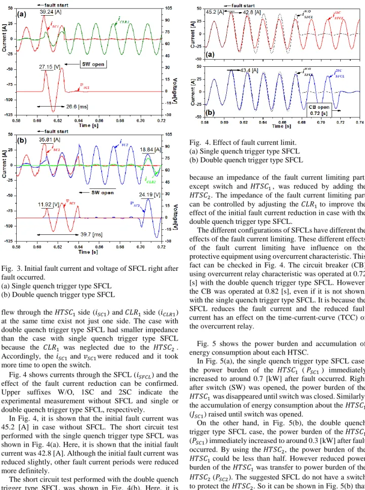
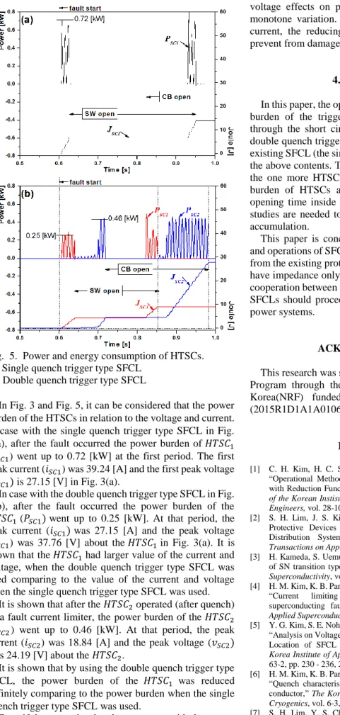
Abstract - This paper analysed a protective equipment in power distribution system linked distribution power system when a superconducting fault

The series connection-type SFCL designed with the additive polarity winding was shown to perform more effective fault current limiting and load voltage

Through the short-circuit tests, the flux-lock type SFCL using transformer winding was shown to perform more effective fault current limiting operation compared

The flux-lock type SFCL designed with the additive polarity winding was shown to perform more effective fault current limiting and load voltage sag