```
1. INTRODUCTION
The continuous increase of electric power due to the industrial development and the expansion of distributed power facilities have increased the fault current. A fault caused by a fault current exceeding the interruption tolerance of a circuit breaker in an electric power system may cause severe damage to a power facility. Various methods have been employed to decrease fault current, including substitution of high-capacity circuit breakers, installation of high-impedance and series reactors, and separation of bus bars.
Superconducting fault current limiters (SFCL) are emerging as an efficient means of reducing fault current, using the characteristic properties of superconductors.
Many studies have been conducted worldwide to apply SFCLs to the limiting of fault current and to actual power systems [1-6].
A transformer type SFCL consists of a transformer and a superconductor element. When a fault occurs, the fault current can be limited by the resistance generated by the superconductor element. The use of a transformer allows an avoiding of direct conduction of the fault current to the superconductor and the setting up of operation conditions by adjusting the transformation ratio of the operational current to the limiting impedance [7-10].
This paper proposes a transformer type SFCL configured by adding a third winding to the iron core of an SFCL model using a double quench of a superconductor element.
A short-circuit simulation experiment was performed to
investigate the fault current limiting characteristics of the double quench by varying the winding ratio of the second winding to the third winding as a key design parameter affecting the fault current limiting characteristics of the proposed SFCL. Based on the results of the simulation experiment, fault current limiting and power burden characteristics of the superconductor element were determined.
2. OPERATIONAL PRINCIPLE AND EXPERIMENTAL METHODS
2.1. Structure and Operational Principle
In conventional transformer type SFCLs, the iron core is connected with a first winding (N1) and a second winding (N2), and a superconductor element (SC1) is connected to the second winding (N2). Fig. 1 shows the structure of the transformer type SFCL proposed in this paper, where a third winding is added.
The operation of the transformer type SFCL with an added third winding may be explained with two states: the normal state and the fault state. In the normal state, the two superconductor elements have zero resistance in the superconducting state, and the magnetic flux generated at the first winding is offset by the magnetic flux generated at the two windings, the second and the third windings, resulting in generation of no voltage from either winding.
In a fault state, with the increase of the fault current at each winding, the current flowing through the superconductor element also increases. When a fault (Received 22 July 2019; revised or reviewed 25 September 2019; accepted 26 September 2019)
Abstract
To protect the power systems from fault current, the rated protective equipment should be installed. However growth of power system scale and concentration of loads caused the large fault current in power transmission system and distribution system. And capacities of installed protective equipment have been exceeded the due to increase of fault current. This increase is not temporary phenomenon but will be steadily as long as the industry develops. The power system need a counter measurement for safety, so superconducting fault current limiter (SFCL) has been received attention as an effective solutions to reduce the fault current. For the above reasons various type SFCL is studied recently. In this paper, the operational characteristics and power burden of trigger type SFCL is studied. The trigger type SFCL has been used for real system research in many countries. And another trigger type SFCL (double quench trigger type SFCL) is also studied. For this paper, short circuit test is performed.
Keywords: double quench, fault current limiting characteristics, superconducting fault current limiter (SFCL), third winding
* Corresponding author: [email protected]
Fig. 1. Schematic configuration of transformer type SFCL with third winding circuit.
current exceeding the critical current flows, the superconductor element causes a quench, which generates resistance at the superconductor element and limits the fault current. When resistance is generated at the superconductor element, the voltage of the superconductor element increases, changing the winding voltage of each winding. The time difference of voltage generation is dependent on the winding ratio between the second and third windings (N2/N3).
The winding of the second and third windings at the transformer type SFCL with an added third winding was in subtractive polarity winding mode. The winding voltage and winding current of the second winding are expressed in Equations (1) and (2):
3 2 1
2 SC SC N
N
V V V
V
(1)2 1
2 SC SC
N
i i
i
(2)2.2. Design and Methods of Experiment
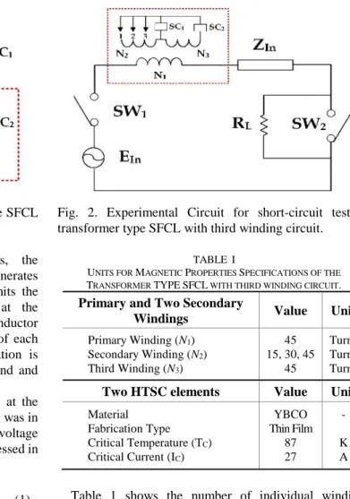
Fig. 2 provides a schematic diagram of the simulation circuit of a transformer type SFCL with an added third winding. An yttrium barium copper oxide (YBCO) thin film having a critical temperature of 87 K and a critical current density (Ic) of 27[A] was used in the experiment as a superconductor element. The superconductor elements were respectively connected to the second and third windings. The transformer type SFCL was connected to the circuit consisting of an alternating current power source voltage of 60 Hz (EIn=120 V), a line impedance (Zln = Rln + jXln = 0.42 + j0.066 [Ω]), and a load resistance (RL = 5 [Ω]).
The winding number of the first (N1) and third windings (N3) included in the transformer type SFCL with added third winding was fixed at 45 turns. The fault current was measured by varying the winding number of the second winding (N2) at 15, 30, and 45 turns.
After adding a switch (SW1), another switch (SW2) was operated at a fault angle of 0° in 5 fault cycles to cause a short-circuit. Simulation short-circuit experiment was performed by measuring the current flowing through each coil and the voltage induced through the current transformer (CT) and the potential transformer (PT).
Fig. 2. Experimental Circuit for short-circuit test of transformer type SFCL with third winding circuit.
TABLE I
UNITS FOR MAGNETIC PROPERTIES SPECIFICATIONS OF THE
TRANSFORMER TYPESFCL WITH THIRD WINDING CIRCUIT. Primary and Two Secondary
Windings Value Unit
Primary Winding (N1) Secondary Winding (N2) Third Winding (N3)
45 15, 30, 45
45
Turns Turns Turns Two HTSC elements Value Unit Material
Fabrication Type Critical Temperature (TC) Critical Current (IC)
YBCO Thin Film
87 27
-
K A
Table 1 shows the number of individual windings included in the transformer type SFCL with added third winding, the shape of the superconducting module, and the critical values.
3. RESULTS AND DISCUSSION
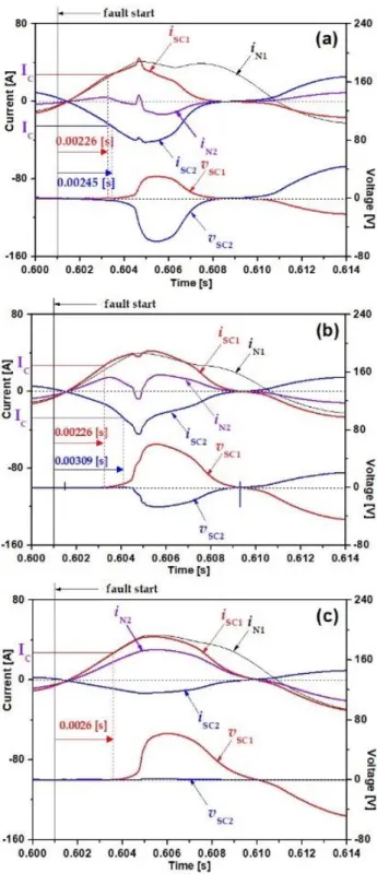
Fig. 3 shows the fault current limiting characteristics of the transformer type SFCL with third winding. Fig. 3(a) shows the current and voltage waveforms when the winding ratio of the second winding to the third winding (N2/N3) was 0.33. The current flowing to the first superconductor element (iSC1) exceeded the critical current density immediately after occurrence of a fault, causing a quench at 0.00226 (s). The current to the second superconductor element (iSC2) caused a quench at 0.00245 (s). The quench time difference between the two superconductor elements was 0.00019 (s).
Fig. 3(b) shows the current and voltage waveforms when the winding ratio (N2/N3) was 0.66. Immediately after the occurrence of a fault, a quench occurred at 0.00226 (s) in the first superconductor element (SC1) and at 0.00309 (s) in the second superconductor element (SC2). The quench time difference between the two superconductor elements was 0.00083 (s). This result shows that the quench time difference increased as the winding ratio increased.
Fig. 3(c) shows the current and voltage waveforms when the winding ratio (N2/N3) was 1. Immediately after the
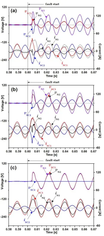
waveform induced at each winding depending on the winding ratio of the second winding to the third winding (N2/N3) in the transformer type SFCL with added third winding.
Fig. 4(a) shows the voltage current characteristics at the winding ratio (N2/N3) of 0.33. A quench occurred in both of the superconductor elements immediately after the fault occurred. The induced voltage generated at each superconductor element limited the fault current. The induced voltage was higher in the second superconductor element (SC2) than in the first superconductor element (SC1). The second winding voltage was the same as that of the first superconductor element (SC1). In addition, the results show that the fault current dramatically increased immediately after the fault occurred. After a 1/2 cycle, the device current decreased due to the quenches in the two superconductor elements.
Fig. 4(b) shows the case in which the winding ratio (N2/N3) was 0.66. The fault current dramatically increased immediately after the fault occurred. Voltage was induced by the quenches generated in the two superconductor elements. The magnitude of the induced voltage was greater in the first superconductor element (SC1) than in the second superconductor element (SC2). This may be because the number of turns was higher in the second winding.
Fig. 4(c) shows the case in which the winding ratio (N2/N3) was 1.0. The fault current dramatically increased immediately after the fault occurred.
The fault current was limited in the first superconductor element (SC1) by the quench. In the second superconductor element (SC2), a partial quench occurred and then recovered, resulting in no induced current. Therefore, the voltage was the same in the first superconductor element (SC1), the second winding, and the third winding in parallel connection.
Finally, Fig. 5 shows the generated resistance and the power burden depending on the winding ratio of the two superconductor elements included in the proposed transformer type SFCL with third winding.
As can be seen in Fig. 5(a), when the winding ratio (N2/N3) was 0.33, resistance was generated in the two superconductor elements by quenches immediately after the fault. The magnitude of the resistance during the fault was greater in the second superconductor element (SC2).
In addition, the power burden was also greater in the second superconductor element (SC2) than in the first superconductor element (SC1).
Fig. 3. Transient fault current limiting characteristics of transformer type SFCL with third winding circuit. (a) Winding ratio N2/N3 is 0.33. (b) Winding ratio N2/N3 is 0.66. (c) Winding ratio N2/N3 is 1.0.
As can be seen in Fig. 5(b), when the winding ratio (N2/N3) was 0.66, resistance was generated in the two superconductor elements by quenches immediately after the fault. In contrast to the case shown in Fig. 5(a), the resistance and the power burden were greater in the first superconductor element (SC1).
As can be seen in Fig. 5(c), when the winding ratio (N2/N3) was 1.0, resistance was generated in the first superconductor element (SC1) by quench. As discussed
Fig. 4. Fault current limiting characteristics of transformer SFCL with third winding circuit. (a) Winding ratio N2/N3 is 0.33. (b) Winding ratio N2/N3 is 0.66. (c) Winding ratio N2/N3 is 1.0.
above about the fault current limiting characteristics depending on the winding ratio, when the winding ratio (N2/N3) was small, double quench occurred in both superconductor elements, and the power burden was greater in the superconductor element connected with the third winding. As the winding ratio increased, double quench occurred in both superconductor elements, but the power burden was greater in the superconductor element connected with the second winding. When the winding ratio was 1.0, a quench occurred only in the superconductor
Fig. 5. Resistances and power burdens of two HTSC elements comprising transformer type SFCL with third winding circuit. (a) Winding ratio N2/N3 is 0.33. (b) Winding ratio N2/N3 is 0.66. (c) Winding ratio N2/N3 is 1.0.
element connected with the second winding, limiting the fault current.
4. CONCLUSIONS
In this study, the fault current limiting and power burden characteristics were compared and analyzed in a transformer type SFCL with an added third winding and found to depend on the winding ratio of the second winding
the first superconductor element. When the winding ratio was 0.66, the resistance and the power burden were greater in the first superconductor element than in the second superconductor element. When the winding ratio was 1.0, quench occurred only in the first superconductor element.
Analysis of the experimental results shows that fault current may be limited according to the design condition of number of turns of second winding. The usefulness of the SFCL proposed in this paper was verified through analysis of the transient current limiting characteristics.
ACKNOWLEDGMENT
This research was supported by Basic Science Research Program through the National Research Foundation of Korea(NRF) funded by the Ministry of Education (2018R1D1A1A09083558)
REFERENCES
[1] E. Thuries, V. D. Pham, Y. Laumond, T. Verhaege, A. Fevrier, M.
Collet, and M. Bekhaled, “Towards the Superconducting Fault Current Limiter,” IEEE Trans. Power Delivery, vol. 6, no. 2, pp.
801-808, 1991.
2002.
[6] S. Lee, J. Yoon, B. Yang, Y. Moon, and B. Lee, “Analysis model development and specification proposal of 154 kV SFCL for the application to a live grid in South Korea,” Physica C, 504, pp.
148–152, 2014.
[7] H. Yamaguchi, T. Kataoka, K. Yaguchi, S. Fujita, K. Yoshikawa, and K. Kaiho, “Characteristics Analysis of Transformer Type Superconducting Fault Current Limiter,” IEEE Trans. Appl.
Supercon., vol. 14, no. 2, pp. 815-818, 2004.
[8] T. Janowski, S. Kozak, B, Kondratowicz-Kucewicz, G.
Wojtasiewicz, and J. Kozak, “Analysis of Transformer Type Superconducting Fault Current Limiters,” IEEE Trans. Appl.
Supercon., vol. 17, no. 2, pp. 1788-1790, 2007.
[9] H. Hatta, T. Nitta, S. Muroya, T. Oide, Y. Shirai, M. Taguchi, and Y.
Miyato, “Study on Recovery Current of Transformer Type Superconducting Fault Current Limiter,” IEEE Trans. Appl.
Supercon., vol. 13, no. 2, pp. 2096-2099, 2003.
[10] S. T. Lim, S. H. Lim, and T. H. Han, “Analysis on operation characteristics and power burdens of the double quench trigger type SFCLs,” Progress in Superconductivity and Cryogenics, vol. 19, no. 2, pp. 33-37, 2017.