Preliminary Design of GBAS Onboard Test Equipment
8
0
0
전체 글
(2) 42. J. Korean GNSS Society 2(1), 41-48 (2013). Therefore, in order to smoothly perform the ground and flight testing and evaluation that will be carried out from the latter half of this year to the first half of next year, customized equipment is required which can be loaded on a car and an aircraft and can evaluate the GBAS ground and flight testing and evaluation items stipulated by the International Civil Aviation Organization (ICAO) (ICAO Doc 8071 Vol. II 2007, ICAO Annex 10 Vol. I 2006, EUROCAE ED-114 2003, FAA-order-8200.1C 2005). In this paper, the hardware and software design of GBAS onboard test equipment is described which was specially customized for the GBAS ground and flight testing and evaluation.. 2. OVERVIEW ON GBAS ONBOARD TEST EQUIPMENT T h e p u r p o s e o f G B A S o n b o a rd t e s t e q u i p m e n t development is to evaluate the functions and performance required for the equipment, prior to commissioning, after the installation of GBAS ground subsystem at the airport. At the pre-commissioning phase, the functions and performance required for the GBAS ground subsystem should be evaluated through the ground and flight testing and evaluation items stipulated by the ICAO 8071 Vol. II as shown in Table 1. Therefore, for the hardware and software design of GBAS onboard test equipment, the hardware components and software functional requirements necessary for the test were obtained by examining the Table 1. GBAS functional requirements (ICAO Doc 8071 Vol. II 2007). Parameter Position domain accuracy (functional test) Pseudorange domain accuracy Continuity (GBAS ground system) Ground Pseudorange Uncertainty Tropospheric delay and residual tropospheric Uncertainty GCID indication Residual ionospheric uncertainty Reference antenna phase centre position accuracy FAS data points accuracy Integrity monitoring for GNSS ranging sources Resistance to interference (range signal) Procedure validation Runway surface coverage Message block header Data content VDB coverage Carrier frequency /Carrier frequency stability Monitering TDMA slot monitoring VDB transmitter power monitor Power in adjacent channels. Annex 10 vol. I Testing 3.7.2.4.1 & Table F/G 3.7.2.4-1 App. B 3.6.7.1.1 G App. B 3.6.7.1.3 G App. B 3.6.7.2.2.4 G App. B 3.6.7.2.3.1 G App. B 3.6.7.2.3.2 App. B 3.6.7.2.3.5 App. B 3.6.7.2.3.3 App. B 3.6.7.2.4.1 App. B 3.6.7.2.6 App. B 3.7 3.7.3.5.3.2 App. B 3.6.3.4.1 App. B 3.6.4. F/G G G G F F/G F G G F/G. 3.7.3.5.4.1 App. B 3.6.7.3 App. B 3.6.7.3.1.2 App. B 3.6.7.3.1.3 3.7.3.5.4.5. G. http://dx.doi.org/10.11003/JKGS.2013.2.1.041. G G G. testing and evaluation items stipulated by the ICAO 8071 Vol. II. As for the GBAS ground and flight testing and evaluation items shown in Table 1, the testing and evaluation is broadly divided into GBAS position accuracy evaluation, continuity evaluation, consistency evaluation of VHF Data Broadcast (VDB) message, VDB field strength evaluation, signal interference evaluation of VDB and Global Positioning System (GPS), and validity evaluation of approach procedure. Therefore, the major functional requirements for the GBAS onboard test equipment to perform the test are as follows. Reception of GPS satellite signal, GBAS VDB signal, and DGPS correction signal Generation of aircraft navigation data, landing guidance data, and flight trajectory data Gathering and analysis of VDB and GPS radio wave output Simple performance monitoring for GBAS navigation and landing guidance data Display and storage for the input/output data of measuring devices On the other hand, as the GBAS onboard test equipment will be used for both the ground testing and evaluation and flight testing and evaluation, the equipment was designed to be operated independently on a car and an aircraft by constructing a customized independent system as shown in Fig. 1. Also, based on the previously obtained functional requirements, the onboard test equipment was designed so that it can output and display aircraft navigation data(position, velocity, and time), approach guidance data, and VDB field strength and signal interference data by receiving the VDB signal transmitted from GBAS ground subsystem and the GPS satellite signal, and that it can store all the collected data for post processing. Moreover, the equipment was designed to have a monitoring function for its own GBAS navigation and approach data so that it can perform simple performance evaluation in real time.. 3. HARDWARE DESIGN 3.1 Hardware components and functions As shown in Table 2, the hardware of GBAS onboard test equipment is composed of controller, measuring devices, power supply, display unit, antennas, and rack. The measuring devices are again composed of MultiMode Receiver (MMR), RF power meter, Differential GPS.
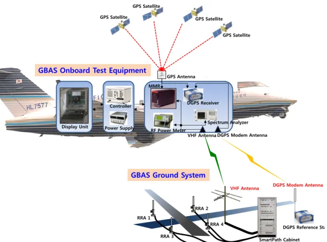
(3) Myeong-Sook Jeong et al. Preliminary Design of GBAS Onboard Test Equipment. 43. GPS Satellite GPS Satellite. GPS Satellite GPS Satellite. GBAS Onboard Test Equipment. GPS Antenna MMR. DGPS Receiver. Controller. Display Unit. Spectrum Analyzer Power Supply. RF Power Meter. VHF Antenna DGPS Modem Antenna. GBAS Ground System VHF Antenna. DGPS Modem Antenna. RRA 2 RRA 1 RRA 4 RRA 3. DGPS Reference Station SmartPath Cabinet. Fig. 1. Concept of GBAS onboard test equipment operation.. Table 2. Equipment component list. Level 1. GBAS onboard test equipment. Level2. Level3. Computer ARINC 429 interface card Controller Analog/Digital interface card Chassis MMR RF power meter Measuring devices DGPS receiver (equipped DGPS modem) Spectrum analyzer Power distributor Power supply DC to AC converter Battery Monitor/Keyboard Display unit Notebook GPS antenna DGPS modem antenna Antennas VHF antenna Splitter Rack. (DGPS) receiver, and spectrum analyzer. The controller controls and stores the input/output data of MMR, RF power meter, spectrum analyzer, and DGPS receiver which are the measuring devices, the display unit displays the data. outputted from the controller for user, and the power supply provides the power necessary for the controller, measuring devices, and display unit. The measuring devices generate various measurement data needed for GBAS performance evaluation by receiving the GPS signal, VDB signal, and DGPS correction signal. The antennas consist of 1 GPS antenna, 1 VHF antenna, and 1 DGPS modem antenna, and provide a signal to each measuring device via each splitter. The rack fastens each component, and protects from external shock. As for the detailed function of each measuring device, the MMR generates the aircraft navigation data and landing guidance data by receiving the GPS signal and GBAS VDB signal which are received via the GPS antenna and VHF antenna. The RF power meter measures the VDB field strength, the spectrum analyzer measures the GPS and VDB signal interference, and the DGPS receiver generates the precision navigation data using a Real Time Kinematic (RTK) survey technique. The position data, which is outputted from the DGPS receiver, is used as the reference trajectory of an aircraft and a car, and will be utilized for the accuracy of GBAS position data outputted from the MMR and the various performance monitoring functions.. http://www.gnss.or.kr.
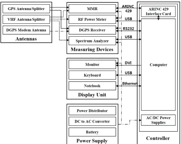
(4) 44. J. Korean GNSS Society 2(1), 41-48 (2013). Fig. 2. Hardware interface of the GBAS onboard test equipment.. Fig. 3. Software functional requirements.. http://dx.doi.org/10.11003/JKGS.2013.2.1.041.
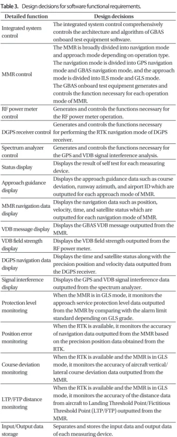
(5) Myeong-Sook Jeong et al. Preliminary Design of GBAS Onboard Test Equipment. 3.2 Hardware interface. Table 3. Design decisions for software functional requirements. Detailed function. Fig. 2 shows the interface among each component of GBAS onboard test equipment, and the controller was designed to transmit and receive the control command and output data for each measuring device. The controller uses the ARINC 429 communication to transmit and receive the input/output data for the MMR, the USB communication for the RF power meter and spectrum analyzer, and the RS232 communication for the DGPS receiver.. Integrated system control. MMR control. RF power meter control. 4. SOFTWARE DESIGN. DGPS receiver control. 4.1 Software functional requirements. Spectrum analyzer control. The functional requirements of GBAS onboard test equipment software for performing the ground and flight testing and evaluation on the GBAS ground subsystem were designed so that they are broadly divided into system control function, output data display function, simple performance monitoring function for the GBAS navigation and approach data, and input/output data storage function for each component of measuring device as shown in Fig. 3, and the detailed design decisions for the functional requirements were defined as shown in Table 3.. Status display. 4.2 Design of software architecture. Signal interference display. The onboard test equipment software operates on the controller of onboard test equipment as shown in Fig. 4. The software controls each measuring device and outputs the navigation and landing guidance data, the VDB message and VDB field strength data, and the status of GPS satellite in real time. The software was designed to have a separate control module for each measuring device to enable independent control and operation of each measuring device. When the RTK is available, the software performs the comparison operation for the two navigation data outputted from the MMR and DGPS receiver, and through this process, performs the simple performance monitoring function for the GBAS navigation data. Also, the onboard test equipment software is able to check the status of each measuring device with the self test function, and immediately outputs the fault data to operator when there is a problem. For each measuring device, the control input data and output data are separated and stored.. 45. Approach guidance display MMR navigation data display VDB message display VDB field strength display DGPS navigation data display. Protection level monitoring. Position error monitoring. Course deviation monitoring. LTP/FTP distance monitoring Input/Output data storage. Design decisions The integrated system control comprehensively controls the architecture and algorithm of GBAS onboard test equipment software. The MMR is broadly divided into navigation mode and approach mode depending on operation type. The navigation mode is divided into GPS navigation mode and GBAS navigation mode, and the approach mode is divided into ILS mode and GLS mode. The GBAS onboard test equipment generates and controls the function necessary for each operation mode of MMR. Generates and controls the functions necessary for the RF power meter operation. Generates and controls the functions necessary for performing the RTK navigation mode of DGPS receiver. Generates and controls the functions necessary for the GPS and VDB signal interference analysis. Displays the result of self test for each measuring device. Displays the approach guidance data such as course deviation, runway azimuth, and airport ID which are outputted for each approach mode of MMR. Displays the navigation data such as position, velocity, time, and satellite status which are outputted for each navigation mode of MMR. Displays the GBAS VDB message outputted from the MMR. Displays the VDB field strength outputted from the RF power meter. Displays the time and satellite status along with the precision position and velocity data outputted from the DGPS receiver. Displays the GPS and VDB signal interference data outputted from the spectrum analyzer. When the MMR is in GLS mode, it monitors the approach service protection level data outputted from the MMR by comparing with the alarm limit standard depending on GLS grade. When the RTK is available, it monitors the accuracy of navigation data outputted from the MMR based on the precision position data obtained from the RTK. When the RTK is available and the MMR is in GLS mode, it monitors the accuracy of aircraft vertical/ lateral course deviation data outputted from the MMR. When the RTK is available and the MMR is in GLS mode, it monitors the accuracy of the distance data from aircraft to Landing Threshold Point/Fictitious Threshold Point (LTP/FTP) outputted from the MMR. Separates and stores the input data and output data of each measuring device.. 4.3 Software CSCI For the GBAS onboard test equipment software, an architectural analysis/design technique was applied which. http://www.gnss.or.kr.
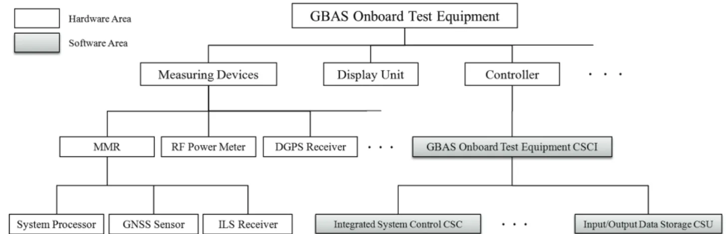
(6) 46. J. Korean GNSS Society 2(1), 41-48 (2013). Fig. 4. Connection architecture of hardware and software.. Fig. 5. CSCI of GBAS onboard test equipment.. performs the modular design by matching the function and characteristic for each Computer Software Unit (CSU) of Computer Software Configuration Item (CSCI) considering the scalability and maintainability. The CSCI of GBAS onboard test equipment software was designed as shown in Fig. 5 based on the detailed software functional. http://dx.doi.org/10.11003/JKGS.2013.2.1.041. requirements defined in Fig. 3.. 4.4 Execution concept of software Fig. 6 shows the execution concept diagram of onboard test equipment software. When the onboard test equipment.
(7) Myeong-Sook Jeong et al. Preliminary Design of GBAS Onboard Test Equipment. 47. Fig. 6. Execution concept of software.. CSCI execution file is performed after applying the power to the onboard test equipment, an integrity system control program controls each measuring device by calling the self test function, MMR control function, RF power meter control function, DGPS receiver control function, and spectrum analyzer control function, and simultaneously stores the input and output data of each measuring device by calling the input/output data storage function. The self test function and each measuring device control function, which were called, again display the output data by calling the status display function, MMR navigation data display function, approach guidance data display function, VDB message display function, VDB field strength display function, DGPS navigation data display function, and signal interference display function. And when the MMR and DGPS receiver are available, the protection level monitoring function, position error monitoring function, course deviation monitoring function, and LTP/FTP distance monitoring function are also called.. 5. CONCLUSIONS When the GBAS ground subsystem is installed at the airport, the functions and performance of the system should be evaluated at the pre-commissioning phase. Therefore, this paper examined the GBAS onboard test equipment which was designed to independently perform the GBAS ground testing and flight testing on a car and an aircraft. In this paper, the hardware components necessary for the GBAS onboard test equipment were presented, and the function of each component and the hardware interface among each component were described. Regarding the software, the software functions required for the testing and evaluation were summarized, and the software CSCI and execution concept which were designed based on the functional requirements were described. The GBAS onboard test equipment is currently being manufactured based on the design described in this paper, and the ground testing and evaluation for the Honeywell SLS-4000 installed at the Gimpo International Airport will be carried out using the equipment in the latter half of this year.. http://www.gnss.or.kr.
(8) 48. J. Korean GNSS Society 2(1), 41-48 (2013). ACKNOWLEDGMENTS. Myeong-Sook Jeong received her B.S., and M.S. degree in School of Aerospace and Mechanical. This research was funded by the Ministry of Land, Transport, and Maritime Affairs through the project, “Development of GBAS Operational Technology”, and the authors are grateful for the grant.. Engineering from Korea Aerospace University, Korea, in 2007 and 2009, respectively. She was with Agency for Defense Development, Korea, as a research engineer from 2010 to 2011. Since 2011, she has been in the CNS/ATM department at Korea Aerospace Research Institute at Daejeon, where she is. REFERENCES. currently a researcher. Her research interests include satellite navigation and GNSS signal processing.. Alvarez, J. M. & Callejo, P. 2012, GBAS Implementation Status and GBAS Activities in Aena, 13th International GBAS Working Group, Langen, Germany. Bae, J., Jun, H. S., Kim, D. M., & Yeom, C. H. 2011, Overview of Worldwide GBAS R&D and Implementation, Current Industrical and Technological Trends in Aerospace, 9, 187-195. Dunkel, W. 2012, DFS GBAS Status, 13th International GBAS Working Group, Langen, Germany. EURO C AE ED-114, 2003, Minimum Operational Performance Specification for Global Navigation Satellite Ground Based Augmentation System Ground Equipment to Support Category I Operations, ed. EUROCAE. FAA-order-8200.1C, 2005, United States Standard Flight Inspection Manual, 4th ed. ICAO Annex 10 Vol. I, 2006, Annex 10 to the Convention o n Int e r nat i o na l C i v i l Av i at i o n : Ae ro nau t i ca l Telecommunications. Volume I - Radio Navigation Aids, 6th ed. ICAO Doc 8071 Vol. II, 2007, Manual on Testing of Radio Navigation Aids, Volume II: Testing of Satellite-based Radio Navigation Systems, 5th ed. Jeong, M. S., Choi, C. H., Ko, W. J., Ko, Y. R., Bae, J. W., et al. 2012, Analysis of GPS Signal Environment for GBAS siting in Gimpo International Airport, 41, 70-78. Jun, H. S., Kim, D. M., & Yeom, C. H. 2010, Study on the Envi ro nm ent Bui ld i ng f or G BAS Approval System Technology Development, Korean Society for Aeronautical Science and Space Sciences Fall Conference, pp. 1554-1557. Weber, O. 2011, Flight Test Report for Bremen SLS-4000, DFS, 2010-271-04. Weber, O. & Dunkel, W. 2011, Ground Test Report for Bremen SLS-4000, DFS, 2010-271-03.. Wan-Jin Ko received his B.S., and M.S. degree in School of Electronics, Telecommunication & Computer Engineering from Korea Aerospace University, Korea, in 2009 and 2011, respectively. He is presently working at Korea Aerospace Research Institute at Daejeon, where he is currently a researcher. His research interests include satellite navigation and reliable embedded system design. Joong Won Bae received his B.S., and M.S. degree in Control and Instrumentation Engineering from Hanyang University, Korea, in 1995 and in 1997 respectively. He is presently working toward a Ph.D. degree at Chungnam National University. He was with Korea Aerospace Industries, Ltd, Korea, as a senior research engineer from 1997 to 2004. Since 2004, he has been in the CNS/ATM department at Korea Aerospace Research Institute at Daejeon, where he is currently an senior researcher. His research interests include Global Navigation Satellite System (GNSS) and its application such as Ground Based Augmentation System(GBAS) and safety assurance for air navigation system. Hyang Sig Jun received his B.S., M.S., and Ph.D. degrees in Electrical Engineering from Pusan National University in Korea, in 1988, 1992, and 2010 respectively. He was with Daewoo Heavy Industries Ltd., as a senior researcher from 1991 to 1999. He was with Korea Aerospace Industries Ltd., as a senior researcher from 2000 to 2003. Since 2004, he has been in Korea Aerospace Research Institute, where he is currently a head of CNS/ATM team and a project manager of GBAS program. He has been involved in several CNS/ATM and Avionics program as a researcher and as a project manager. His research interests include CNS/ATM, GNSS and Avionics.. http://dx.doi.org/10.11003/JKGS.2013.2.1.041.
(9)
수치
+2

관련 문서
t-test and F-test were employed to find out the influence of child gender, birth of order and family atmosphere on parent communication style and child
The labial surfaces of 24 extracted bovine incisors were used. For the ground enamel, flat enamel surfaces at labial aspect were ground. However, for
2. The finite element is calculating using tension test of uni-direction 0° and 90°, compression test of uni-direction 0° and 90° and shear test results and, the results
– Example, for a desert project, the engineer might have to go as high as 6% above the optimum water content as a target for all water application calculations so that
- Spring is any natural occurrence where water flows on to the surface of the earth from below the surface (aquifer surface meets the ground surface)5. - Ground
Near Nong Khai, on a terrace of the Mae Nam Khong, adequate water from shallow dug wells, 30 to 50 feet deep in alluvial sand and gravel, supply municipal
Basic aspects of AUTOSAR architecture and methodology Safety mechanisms supported by AUTOSAR.. Technical safety concepts supported by AUTOSAR Relationship to ISO
1 John Owen, Justification by Faith Alone, in The Works of John Owen, ed. John Bolt, trans. Scott Clark, "Do This and Live: Christ's Active Obedience as the
