공학석사 학위논문
인간의 움직임을 적용한 인체크기의
이족보행로봇 설계 및 기구학 해석
Design and Kinematics Analysis of a Human-Sized Biped
Walking Robot applied to Motion of Human
지도교수 최 형 식
2008 년 2 월
한국해양대학교 대학원
기 계 공 학 과
本 論文을 李宗勳의 工學碩士 學位論文으로 認准함.
위 원 장 왕 지 석 (인)
위 원 최 형 식 (인)
위 원 조 종 래 (인)
2008 년 2 월
한국해양대학교 대학원
목 차
Abstract
기 호 설 명
그 림 목 차
표 목 차
제 1 장 서론 ...1 제 2 장 이족보행로봇의 구성 ...3 2.1 이족보행로봇 전체시스템 구성 ...5 2.2 이족보행로봇 머리 기구부 구성 ...8 2.3 이족보행로봇 허리 기구부 구성 ...10 2.4 이족보행로봇 팔 기구부 구성...11 2.5 이족보행로봇 하체 기구부 구성 ...15 2.6 이족보행로봇 제어시스템 구성 ...20 제 3 장 이족보행로봇의 기구학 해석 ...22 3.1 이족보행로봇 D-H 구성...22 3.2 이족보행로봇 머리 기구학 해석 ...27 3.3 이족보행로봇 팔 기구학 해석...30 3.4 이족보행로봇 다리 기구학 해석 ...35 3.5 이족보행로봇의 기구학적 상호관계 적용...40 제 4 장 이족보행로봇의 관절 구동기 해석...41 4.1 4절 링크의 관절 관계식...41 4.2 4절 링크 구조의 관절 구동기 부하토크 해석 ...47 4.3 4절 링크 구조의 관절 구동기 해석 데이터...52 제 5 장 이족보행로봇의 기구부 구조해석 ...55 5.1 유한요소 모델...55 5.2 유한요소 해석...57 제 6 장 이족보행로봇의 외장케이스 설계 ...63 6.1 외장케이스의 3D 설계와 금형 제품 ...636.2 외장케이스의 경량화 ...65 제 7 장 결론 ...66
Design and Kinematics Analysis of a Human-Sized
Biped Walking Robot applied to Motion of Human
Jong-Hoon Lee
Department of Mechanical Engineering
Graduate School, Korea Maritime University
Abstract
This thesis is about 27 degree-of-freedom humanoid robot named KUBIR-3 which has height of 170cm and weight of 72kgf. KUBIR-3 is composed of four parts: the head, body, arms and legs. The head part is composed of two degree-of-freedom which are directly connected by the actuator motor and speed reducer. The body was designed to have one degree-of-freedom to give roll motion of the robot. The arms were designed to have six d.o.f where three joints are composed of the four-bar-link joint actuator and the other were designed to have the actuator motor with the speed reducer as the harmonic driver. The legs were designed to have six d.o.f. where three joints are composed of the four-bar-link joint actuator and the other were designed to have the actuator motor with the speed reducer as the harmonic driver. At the shoulder, elbow, and wrist joints of arms and at the thigh, knee, and ankle joints of legs, the four-bar link joint actuator was applied to transfer the heavy loads.
To analyze the kinematics of KUBIR-3, the D-H convention was applied to the joints of the robot. For this, the center of the robot body was selected as the base coordinate. Based on this, the relative positions of the arms and legs were defined. Also, using this, the inverse kinematics analysis was made.
made by the FEM analysis using the CATIA. To do these, modeling of the arm and leg was made. The results of the simulation showed the safe design of the link of the arm and leg.
For the analysis of the four-bar link joint of KUBIR-3, static force equation according to the load torque was analyzed. The analyzed data of this equation showed the validity of the appropriate choosing of the actuator motors for supporting heavy loads. The case molding of the KUBIR-3 was designed and constructed based on the 3D modeling using the CATIA
기 호 설 명
iA
각 관절의 i 좌표계에 대한 동차 변환 행렬 j iT
각 기구부의 i 좌표계에 대한 j 좌표계까지의 동차 변환 행렬 iθ
각 기구부의 회전 관절 i 번째의 관절 변수 ip
각 기구부 i 의 말단 위치벡터 il
4절 링크의 i 의 링크길이φ
4절 링크의 관절 변형량 각d
4절 링크의 미끄럼 변형량 iM
4절 링크에 작용하는 기구부 i 의 자중 iF
각 관절에 가해지는 i 의 미끄럼 방향의 힘 iτ
각 관절의 회전중심에 작용하는 i 의 토크그 림 목 차
Fig. 2.1 Structure of KUBIR-1 ...4
Fig. 2.2 Structure of KUBIR-2 ...4
Fig. 2.3 Structure of KUBIR-3 ...4
Fig. 2.4 Structure of four bar link ...5
Fig. 2.5 Front and side view of the head ...8
Fig. 2.6 Rotation range of the head ...8
Fig. 2.7 The waist frame and joint ...10
Fig. 2.8 Gravity compensator of the waist joint ...10
Fig. 2.9 3D model of the shoulder joint ...11
Fig. 2.10 Rotation range of the shoulder pitch joint...11
Fig. 2.11 Shoulder joint ...11
Fig. 2.12 3D model of the elbow joint...12
Fig. 2.13 Rotation range of the elbow pitch joint ...12
Fig. 2.14 Elbow joint...12
Fig. 2.15 3D model of the wrist joint ...13
Fig. 2.16 Rotation range of the wrist pitch and yaw joint ...13
Fig. 2.17 Wrist joint...13
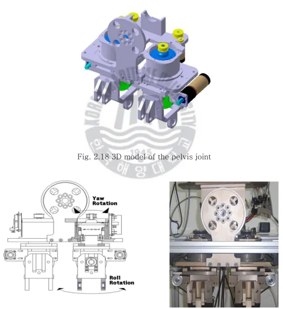
Fig. 2.18 3D model of the pelvis joint...15
Fig. 2.19 Rotation range of the pelvis yaw and roll joint ...15
Fig. 2.20 Pelvis joint...15
Fig. 2.21 3D model of the thigh joint ...16
Fig. 2.22 Rotation range of the thigh pitch joint...16
Fig. 2.23 Thigh joint ...16
Fig. 2.24 3D model of the knee joint ...17
Fig. 2.25 Rotation range of the knee pitch joint ...17
Fig. 2.26 Knee joint ...17
Fig. 2.27 3D model of the ankle joint...18
Fig. 2.28 Rotation range of the ankle pitch and roll joint...18
Fig. 2.29 Ankle joint ...18
Fig. 2.30 Motor Controller ...20
Fig. 2.32 Total control system of the KUBIR-3 ...21
Fig. 3.1 D-H coordinates for the KUBIR-3 ...24
Fig. 3.2 D-H coordinates for the head ...27
Fig. 3.3 D-H coordinates for the arm ...30
Fig. 3.4 D-H coordinate for the leg ...35
Fig. 4.1 Four-bar link structure...41
Fig. 4.2 Four-bar link modeling for the shoulder joint ...43
Fig. 4.3 Four-bar link modeling for the elbow joint...44
Fig. 4.4 Four-bar link modeling for the wrist joint ...44
Fig. 4.5 Four-bar link modeling for the thigh joint ...45
Fig. 4.6 Four-bar link modeling for the knee joint...45
Fig. 4.7 Four-bar link modeling for the ankle joint...46
Fig. 4.8 Torque analysis of the shoulder joint...47
Fig. 4.9 Torque analysis of the elbow joint ...48
Fig. 4.10 Torque analysis of the wrist joint ...48
Fig. 4.11 Torque analysis of the thigh joint ...49
Fig. 4.12 Torque analysis of the knee joint...49
Fig. 4.13 Torque analysis of the ankle joint ...50
Fig. 4.14 Torque analysis of the shoulder joint...52
Fig. 4.15 Torque analysis of the elbow joint ...52
Fig. 4.16 Torque analysis of the wrist joint ...53
Fig. 4.17 Torque analysis of the thigh joint ...53
Fig. 4.18 Torque analysis of the knee joint...54
Fig. 4.19 Torque analysis of the ankle joint ...54
Fig. 5.1 Finite element model of the arm product ...55
Fig. 5.2 Finite element model of the leg product ...56
Fig. 5.3 Displacement of the KUBIR-3 arm...58
Fig. 5.4 FEM stress result of the KUBIR-3 arm ...59
Fig. 5.5 FEM displacement result of the KUBIR-3 arm ...59
Fig. 5.6 Displacement of the KUBIR-3 leg ...61
Fig. 5.7 FEM stress result of the KUBIR-3 leg...62
Fig. 5.8 FEM displacement result of the KUBIR-3 leg ...62
Fig. 6.1 3D model of the KUBIR-3 cases ...63
표 목 차
Table 2.1 Specification of KUBIR-series ...3
Table 2.2 Specification of KUBIR-3 ...6
Table 2.3 Degree of freedom of KUBIR-3 ...7
Table 2.4 Specification of the joint actuator for head part ...9
Table 2.5 Specification of the joint actuator for arm part ...14
Table 2.6 Specification of the joint actuator for leg part...19
Table 3.1 Link parameter for the KUBIR-3 head...25
Table 3.2 Link parameter for the KUBIR-3 arm ...25
Table 3.3 Link parameter for the KUBIR-3 leg ...26
Table 4.1 Length of the link...43
Table 4.2 Constants of the load torque in each joint ...51
Table 5.1 Material property ...56
Table 5.2 Element type and number ...56
Table 5.3 Displacement and stress of the KUBIR-3 arm...57
Table 5.4 Displacement and stress of the KUBIR-3 leg...60
제 1 장 서론
오늘날 로봇은 로봇공학이라 하여 기구학(kinematics), 동역학(dynamics), 제어 (control)와 같이 다양한 분야가 서로 상호 작용하는 최첨단 분야이다. 그렇기에 로봇 에 관한 연구는 다양한 분야에 종사하는 연구원들이 서로 협력하여야 최고 목표점에 도달 할 수가 있다. 현재 로봇에 관한 연구 분야는 산업용 자동화 로봇, 극한 환경의 탐사 로봇, 가정용 생활 로봇, 인간을 모방한 이족보행로봇 등 다양한 목적으로 세계에서 연구가 진행 중 에 있다. 그리고 인간의 실생활에 직접적으로 편의를 제공할 수 있는 로봇 개발의 노 력도 꾸준히 진행되어 왔는데, 그 연구의 중심이 바로 이족보행로봇이다[14]. 2000년 에 개발된 혼다(Honda)-아시모(Asimo)의 발표가 이족보행로봇에 대한 연구개발의 촉 진제로 보며 여러 단체에서 로봇에 대한 관심이 부각되기 시작 하였다. 이족보행로봇 에 대한 연구는 현재까지 단연 일본이 선두이며, 이를 연구하는 기관도 혼다(Honda), 소니(Sony), 가와다(Kawada), 후지쓰(Fujitsu), 도요타(Toyota), AIST, 동경대, 와세다 대 등 기업 및 대학에 이르기까지 폭 넓은 기관에서 연구가 되고 있다[1-3,13]. 물론 한국 대표 연구기관인 KAIST에서의 휴보(HUBO)가 있다. 이렇게 국내에서도 뒤늦게 여러 기업 및 대학에서 활발히 로봇의 연구개발이 진행되고 있다. 로봇 기술력도 일본 못지않게 세계적으로 인정을 받고 있는 현실에 있다. 보행로봇 기술의 연구는 1960년 대 후반 Vokobratovic의 이족보행로봇에 관한 모델링을 제안한 이후 많은 연구가 진 행되어 왔다. 동적 보행 시 로봇 걸음새 동작의 특성을 파악하고 이를 제어하는 연구 [4], 3자유도 이족보행로봇의 토크를 줄이기 위하여 경로 계획을 이용한 제어[5], 5자 유도의 이족보행로봇의 운동방정식을 비선형 디커플링 방법에 의해 선형화시켜 거동을 제어하는 연구[6], 토크 센서를 이용하여 9자유도의 로봇의 보행 제어[7], 로봇 운동 패턴학습[15], 보행동작의 모델링과 선형화 제어로 인한 상태공간의 안정도 해석[8], 5자유도 로봇의 모델링과 슬라이딩모드 제어를 통한 보행궤적 추적제어에 관한 연구들 이 수행되었다[9, 10]. 본 논문 연구배경은 기술적 측면과 산업적 측면에서 접근하였다. 기술적 측면은 볼 나사 및 4절 링크를 새로운 메커니즘 구동으로 적용하였다. 이는 소형경량의 고토크 관절 구동기로 휴머노이드 개발기술을 확보하고자 하였다. 그리고 산업적 측면으로는 고중량물 이송가능한 로봇으로 극한 환경이나 산업현장에 적용하여 작업능률 향상에 도움이 되고자 한 것이다. 또한 인간과 유사한 동작의 구현 및 친숙한 이미지의 이족보행로봇의 개선에 초점을 두었다. 그래서 기계공학을 기준으로 한 로봇 설계와 기구 학 해석을 다루고자 한다. 지금까지 개발된 이족보행로봇의 메커니즘(mechanism)은 구동기(actuator)와 관절과의 운동관계가 직결 타입의 구동이지만 본 논문에서 개발된 이족보행로봇은 구동 메커니즘(mechanism)이 다른 고중량물 이송능력을 갖춘 4절 링 크 구조의 관절타입을 소개 할 것이다. 그리고 기존에 연구되었던 KUBIR-1과 2에서 의 동작속도와 중량, 관절의 유격현상 등의 문제점들을 보완하여 기구부의 설계에 대 해 설명하였다. 따라서 본 논문의 2장에서는 개선된 KUBIR-3의 전체 시스템과 기구 부의 구성 및 제원에 대하여 설명하였다. 3장에서는 KUBIR-3의 기구학 해석을 수행하 여 구동에 따른 각 말단장치(end-effector)의 기구학 방정식을 유도하였다. 4장에서는 개발된 로봇 관절 구동기에 작용하는 힘들을 도식화하여 일반적인 방정식을 유도하였 다. 그리고 각 관절에 사용된 구동기의 부하토크를 해석하여 이론과 실제적용의 타당 성을 검토하였다. 5장에서는 자체 중량 및 외부하중에 대한 기구적인 구조해석을 실시 하여 설계의 타당성을 검토하였고, 6장에서는 KUBIR-3의 외장 케이스의 금형 소개와 경량의 외장 케이스 제작에 대해 소개하였다. 마지막으로 7장에서는 결론에 대하여 설 명하였다.
제 2 장 이족보행로봇의 구성
사절 링크 구조를 가진 이전의 이족보행로봇인 KUBIR-1 및 KUBIR-2들은 여러 가 지 문제점을 가지고 있었다. 아래 Fig. 2.1 의 KUBIR-1 과 같은 경우는 사절 링크 구 조 설계의 복잡함과 운동 반경의 제한으로 관절의 동작속도가 저속이었다. 그리고 중 량이 무거운 문제도 있었다. 이를 일부 해결한 후속 모델 Fig. 2.2 의 KUBIR-2는 보 다 고성능의 구동기(Actuator)를 장착하였고, 사절 링크를 모듈화하여 보다 나은 외형 디자인으로 제작하였다. 또한 불필요한 무게의 최소화와 무게중심 면에도 안정감을 구 사하였다. 그러나 관절의 이음의 유격 및 로봇 움직임의 부자연스러움 등의 KUBIR-2 의 단점이 있었기에 이를 더 보강한 모델이 본 논문에서 제시한 Fig. 2.3 의 KUBIR-3 이다. KUBIR-3는 이전까지 실험에 의해 발견된 각 부 관절과의 조인트의 유격완화, 링크 부분의 내구성 강화, 로봇 팔의 인간과 유사한 운동 구현 등의 문제점을 해결하 였다. 또한 매끈한 외장 케이스를 설치 함으로써 한층 더 부드러운 이미지로 사람들에 게 친근한 로봇으로 변신하였다. Table 2.1 은 KUBIR 로봇들의 제원을 나타내고 있다.Table 2.1 Specification of KUBIR-series
Height (cm)
Frame weight (kgf)
DOF Actuator
KUBIR-1 172 92 25 60W DC Servo motor
KUBIR-2 168 92 29 150W DC Servo motor
Fig. 2.1 Structure of KUBIR-1
Fig. 2.2 Structure of KUBIR-2
2.1 이족보행로봇 전체시스템 구성
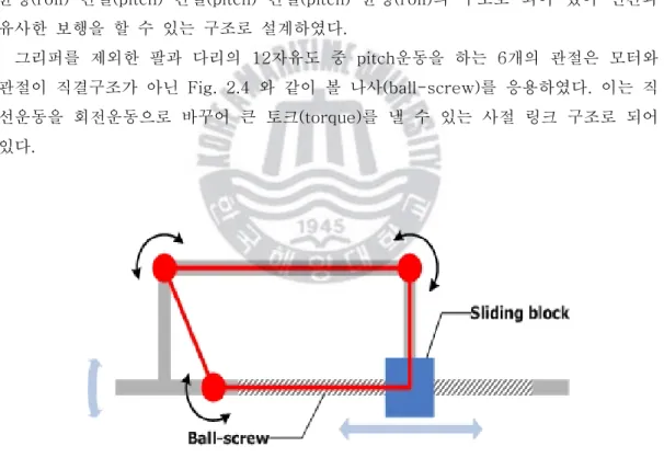
새롭게 개발된 KUBIR-3의 전체시스템 구성은 Table 2.2 와 Table 2.3 과 같다. 전 체 로봇의 신장은 170cm, 몸무게는 72kgf이다. 머리 2자유도, 한 팔당 6자유도, 허리 1자유도, 한 다리당 6자유도의 총 27자유도를 가지는 휴머노이드 이족보행로봇이다. 로봇의 머리에는 눈에 해당하는 CCD 카메라 2대가 장착되어 있으며 머리는 yaw와 pitch운동이 가능하다. 팔의 6자유도는 어깨부터 회전(yaw)-관절(pitch)-관절(pitch)-관절(pitch)-균형(roll)의 구조와 말단장치인 그리퍼(gripper)가 사람의 손 역할로 장착 되어 물건을 잡을 수 있다. 허리의 1자유도는 로봇의 보행 및 하중의 부하에 의한 무 게 중심을 제어하는 역할을 담당하고 있다. 마지막으로 다리의 6자유도는 회전(yaw)-균형(roll)-관절(pitch)-관절(pitch)-관절(pitch)-균형(roll)의 구조로 되어 있어 인간과 유사한 보행을 할 수 있는 구조로 설계하였다. 그리퍼를 제외한 팔과 다리의 12자유도 중 pitch운동을 하는 6개의 관절은 모터와 관절이 직결구조가 아닌 Fig. 2.4 와 같이 볼 나사(ball-screw)를 응용하였다. 이는 직 선운동을 회전운동으로 바꾸어 큰 토크(torque)를 낼 수 있는 사절 링크 구조로 되어 있다.
Table 2.2 Specification of KUBIR-3
Height 170 [㎝]
Weight 72 [kgf]
DC Servo motor + Harmonic speed reducer Arm
Leg
Waist DC Servo motor +
Ball Screw Actuator
Head DC motor
Main controller Embedded Single-board Computer Control unit
Joint controller TMS320LF2407 + Driver6
Power capacity 24V / 50AH
Sensory device
2 CCD camera / Image grabber Tilt sensor, FSR sensor Magnetic sensor, Proximity sensor
Table 2.3 Degree of freedom of KUBIR-3
Head 2 DOF
Left 6 DOF
(shoulder 2 + elbow 1 + wrist 2 + hand 1) Arm
Right 6 DOF
(shoulder 2 + elbow 1 + wrist 2 + hand 1)
Waist 1 DOF
Left 6 DOF
(pelvis 2 + thigh 2 + knee 1 + ankle 1) Leg
Right 6 DOF
(pelvis 2 + thigh 2 + knee 1 + ankle 1)
2.2 이족보행로봇 머리 기구부 구성
이족보행로봇의 머리는 Fig. 2.5 와 같이 2자유도를 가지고 있으며, 인간의 눈과 같 은 역할을 하는 2대의 CCD 카메라가 장착되어 있어 로봇 전방의 물체를 인식하는 역 할을 한다. Table 2.4 와 같이 2개의 모터가 감속기와 풀리로 직결로 연결된 관절을 구성하고 있다. 그리고 Fig. 2.6 과 같이 전방을 기준으로 상하 좌우 45°의 운동범위를 가지고 있다.Fig. 2.5 Front and side view of the head
Table 2.4 Specification of the joint actuator for head part
Axis Motion Motor power [W]
Pulley ratio Ratio of speed reducer
0 yaw 1.5 1:2.85 1:104
2.3 이족보행로봇 허리 기구부 구성
이족보행로봇의 허리는 모터와 감속기가 총 1:645로 직결 연결된 구조로 1자유도를 가진다. 그리고 Fig. 2.7 과 같이 감속기 앞에 중력 완충장치가 장착되어 스프링의 탄 성력으로 로봇의 상체가 중력에 의해 기울어지는 현상을 사전에 방지 가능하다. 그리 고 로봇보행 시 안정적 움직임을 구현 할 수 있다.Fig. 2.7 The waist frame and joint
2.4 이족보행로봇 팔 기구부 구성
이족보행로봇의 양팔은 총 12자유도를 가지고 있다. 4개의 직결구조 회전(yaw)축과 6개의 4절 링크 구조 관절(pitch)축, 그리고 2개의 말단장치인 그리퍼 1축으로 구성되 어 있다. 아래 Fig. 2.9 는 어깨부분 직결구조의 회전(yaw)축이 팔 전체를 회전할 수 있도록 된 관절 구조이다. 그리고 다음 2개의 관절(pitch)축이 아래에 위치하고 있다. 어깨부분의 회전(yaw)운동은 몸체와 35°로 기울어져 있어 회전축으로 180° 운동이 가 능하다. 첫 번째 관절(pitch)축은 Fig. 2.10 과 같이 로봇몸체로부터 안쪽으로 6°, 바깥 쪽으로 30°의 운동범위를 갖는다.Fig. 2.9 3D model of the shoulder joint
6° 30°
6° 30°
Fig. 2.10 Rotation range of the
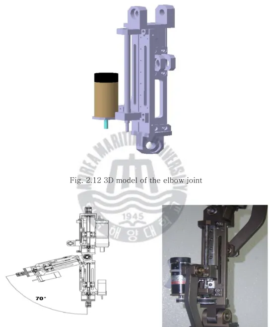
팔꿈치관절은 Fig. 2.14 와 같은 구조이며, 어깨의 두 번째 관절(pitch)축으로 Fig.2.13 과 같이 몸체의 앞쪽으로 70°의 운동범위를 갖는다.
Fig. 2.12 3D model of the elbow joint
70° 70°
Fig. 2.13 Rotation range of the elbow
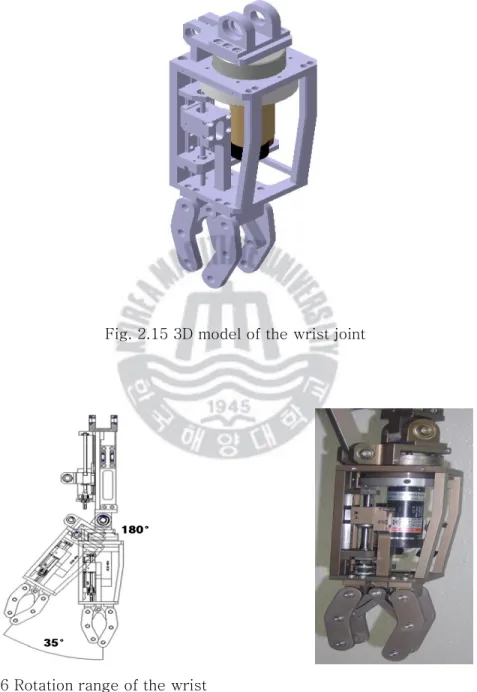
손목부분은 Fig. 2.17 과 같이 손목의 균형(roll)축과 말단장치인 그리퍼의 1축 이렇 게 2개의 관절로 구성된다. 균형(roll)축은 180°의 운동범위를 가지며, 팔꿈치의 세 번 째 관절(pitch)축으로 Fig. 2.16 과 같이 안쪽 35°의 범위에서 운동이 이루어진다.
Fig. 2.15 3D model of the wrist joint
35°
180°
35°
180°
Fig. 2.16 Rotation range of the wrist
Table 2.5 는 양팔에 사용된 관절 구동기의 사양을 나타낸다.
Table 2.5 Specification of the joint actuator for arm part
Axis Type of actuator Motion Motor power [W] Pulley ratio Ratio of speed reducer Ball screw lead[㎜] 0 Directly connected yaw 60 - 1 : 160 - 1 4 bar-link pitch 150 1 : 1 1 : 4.3 2 2 4 bar-link pitch 60 1 : 4.8 - 1 3 4 bar-link pitch 60 1 : 1.75 - 1 4 Directly connected yaw 60 - 1 : 100 - 5 4 bar-link gripper 18 1 : 1.75 - 1
2.5 이족보행로봇 하체 기구부 구성
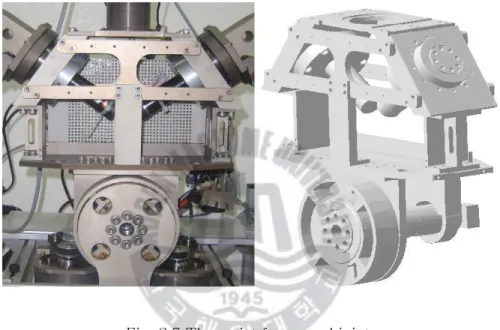
골반 관절은 보행 시 로봇의 무게 중심이동과 방향전환에 영향을 미치는 중요한 관 절이다. 골반관절은 Fig. 2.19 와 같이 양쪽 다리의 회전(yaw)운동, 균형(roll)운동으로 4자유도로 구성되며 회전(yaw)운동은 로봇의 회전역할을 하고, 균형(roll)운동은 보행 시 로봇의 균형역할을 한다.
Fig. 2.18 3D model of the pelvis joint
Yaw Rotation Roll Rotation Yaw Rotation Roll Rotation
Fig. 2.19 Rotation range of the pelvis
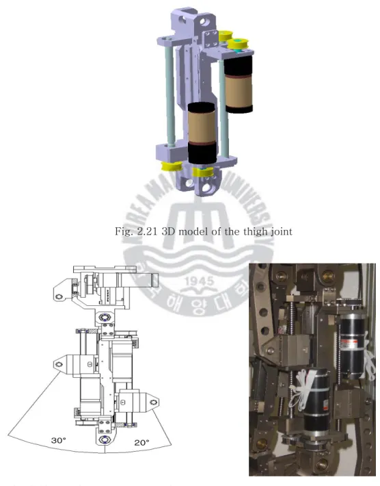
이족보행로봇의 다리구조는 허벅지관절, 무릎관절 그리고 발목관절로 이루어져 있다. 허벅지관절은 2축 구동기로 Fig. 2.23 와 같다. 다음은 3D 모델과 앞으로 30°, 뒤로 20°의 운동범위를 나타내고 있다.
Fig. 2.21 3D model of the thigh joint
30° 20° 30° 20°
Fig. 2.22 Rotation range of the thigh
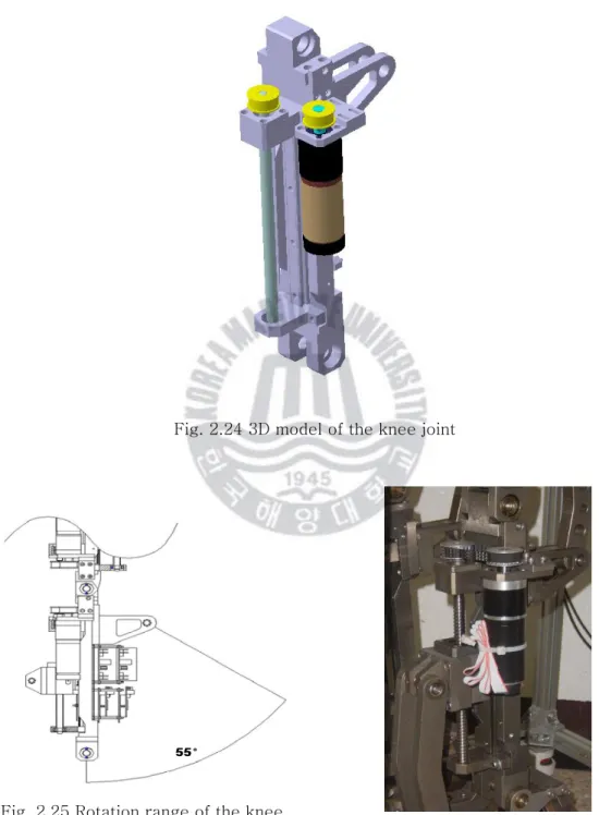
무릎관절은 Fig. 2.26 와 같고, 다음은 3D 모델과 뒤로 55°의 운동범위를 나타내고 있다.
Fig. 2.24 3D model of the knee joint
55° 55°
Fig. 2.25 Rotation range of the knee pitch joint
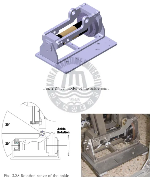
발목관절은 Fig. 2.29 와 같고, 균형(roll)운동으로 로봇보행 시 로봇 전체균형을 담 당하는 역할을 한다. 다음은 3D 모델과 앞뒤 30° 및 좌우 회전 운동범위를 나타내고 있다.
Fig. 2.27 3D model of the ankle joint
30° 30° Ankle Rotation 30° 30° Ankle Rotation
Fig. 2.28 Rotation range of the ankle pitch and roll joint
Table 2.6 은 하체에 사용된 관절 구동기의 사양을 나타낸다.
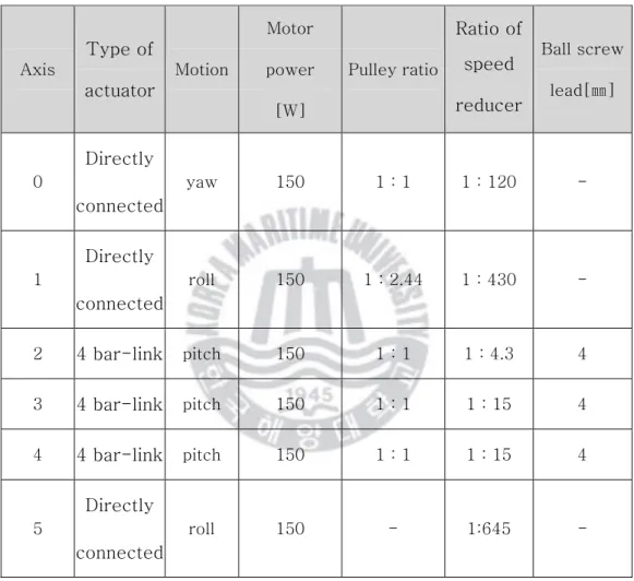
Table 2.6 Specification of the joint actuator for leg part
Axis Type of actuator Motion Motor power [W] Pulley ratio Ratio of speed reducer Ball screw lead[㎜] 0 Directly connected yaw 150 1 : 1 1 : 120 - 1 Directly connected roll 150 1 : 2.44 1 : 430 - 2 4 bar-link pitch 150 1 : 1 1 : 4.3 4 3 4 bar-link pitch 150 1 : 1 1 : 15 4 4 4 bar-link pitch 150 1 : 1 1 : 15 4 5 Directly connected roll 150 - 1:645 -
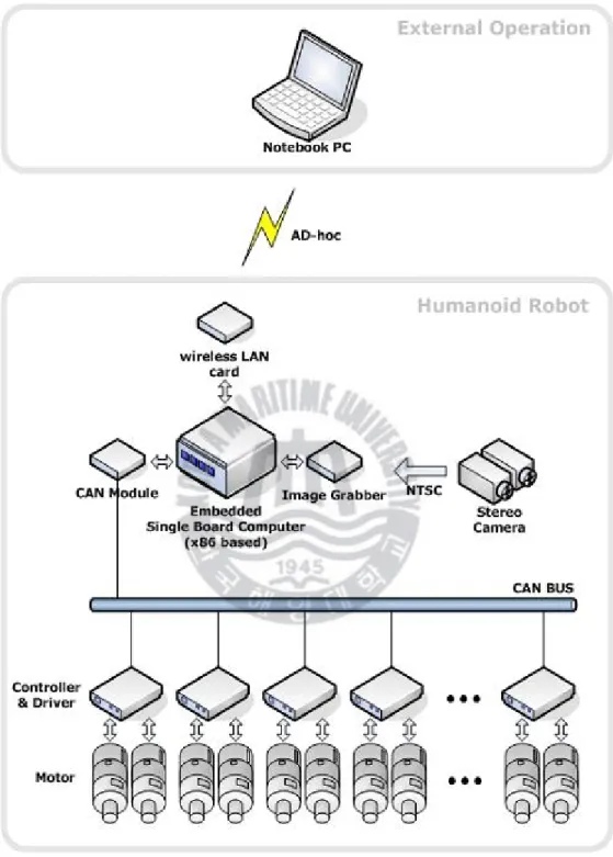
2.6 이족보행로봇 제어시스템 구성
개발된 로봇은 27개의 관절과 모터를 가지고 있다. 아래 Fig. 2.32 는 이전 로봇의 제어 시스템으로 향후에 장착 할 로봇의 전체 제어시스템을 나타내고 있다. KUBIR-3 에는 상업용 로봇 제어기가 아닌 자체 개발된 제어 시스템을 사용하여 2개의 모터는 Fig. 2.30 인 하나의 컨트롤러(controller)와 Fig. 2.31 인 드라이버로 구성된 관절제어 기로 제어되고, 여러 개의 관절제어기는 CAN(Controller Area Network)으로 연결되어 있다. 관절제어기의 상위에는 로봇의 주제어기인 임베디드용 소형 컴퓨터가 있어 각 관절의 구성조건에 따른 연산을 하고, 관절제어기로 제어명령을 내리게 된다. 이로써 이족보행로봇의 전체 관절이 제어되어 로봇 움직임을 만들 수 있게 된다. 개발에 사용된 컴퓨터에는 무선 랜카드가 장착되어 있어 외부에서 로봇으로 명령을 내릴 수 있다. 반대로 관절 각 및 에러 등과 같은 로봇의 현재상태를 외부로 알릴 수 도 있다. 또한 로봇의 머리 부분에 설치된 2대의 CCD 카메라로부터 들어오는 아날로 그 영상신호를 획득하여 이진화하기 위해 주제어기에는 이미지 그래버가 설치되어 있 으며 로봇은 영상처리를 통해 입력된 영상에서 특정 물체를 검출하여 관절제어에 적용 할 수 있도록 되어 있다.
Fig. 2.30 Motor Controller
제 3 장 이족보행로봇의 기구학 해석
로봇의 안정된 보행을 위해서는 로봇 하체의 관절에 대해 기구학(kinematics) 해석 이 필요하다. 본 논문에서는 로봇의 보행과 카메라로 사물을 인식하여 팔로 사물을 잡 는 동작이 주안점이다. 그래서 로봇 전체시스템에 대하여 기구학적 해석을 하였다. 로 봇의 허리 중심부를 모든 로봇관절의 기준점으로 머리의 카메라를 2축, 다리를 6축 그 리고 팔을 6축으로 매니퓰레이터(manipulator)로 적용하였고, 다시 다리 기구학 해석에 서 기준 좌표계와 말단장치(end effecter)의 관계인 동차 변환을 역으로 기구학을 해석 하여 로봇 전체시스템의 기구학적 호환이 가능하게 해석하였다.3.1 이족보행로봇 D-H 구성
로봇의 기구학을 해석하기 위해서는 각 링크의 좌표계를 체계적으로 선택할 수 있어 야 한다. 그래서 기구학에서 사용하는 동차 변환(Homogeneous Transform)을 이용하 면 간편하다. 로봇의 각 관절에 각도가 주어 졌을 때 말단장치의 위치와 방향을 결정 하기 위한 이족보행로봇의 순 기구학 방정식은 보편적으로 많이 사용하는 좌표계 선정 방법이 Denavit-Hartenberg (D-H) 규약이다. . 좌표계 설정 시 D-H 규약은 다음과 같다. (D-H 1)x
1 축은 0z
축과 수직이다. (D-H 2)x
1 축은z
1 축과 수직이다.D-H 규약은 4개의 기본 변환 행렬의 곱으로 각 관절의 동차 변환 행렬
A
i로 표현 한다. i i i i zd xa x zi
Rot
Trans
Trans
Rot
A
=
,θ , , ,α⎥
⎥
⎥
⎥
⎦
⎤
⎢
⎢
⎢
⎢
⎣
⎡
−
⎥
⎥
⎥
⎥
⎦
⎤
⎢
⎢
⎢
⎢
⎣
⎡
⎥
⎥
⎥
⎥
⎦
⎤
⎢
⎢
⎢
⎢
⎣
⎡
⎥
⎥
⎥
⎥
⎦
⎤
⎢
⎢
⎢
⎢
⎣
⎡
−
=
1
0
0
0
0
0
0
0
0
0
0
1
1
0
0
0
0
1
0
0
0
0
1
0
0
0
1
1
0
0
0
1
0
0
0
0
1
0
0
0
0
1
1
0
0
0
0
1
0
0
0
0
0
0
i i i i i i i i i iC
S
S
C
a
d
C
S
S
C
α
α
α
α
θ
θ
θ
θ
=⎥
⎥
⎥
⎥
⎦
⎤
⎢
⎢
⎢
⎢
⎣
⎡
⋅
⋅
−
⋅
⋅
⋅
⋅
−
1
0
0
0
0
i i i i i i i i i i i i i i i i id
C
S
S
a
S
C
C
C
S
C
a
S
S
C
S
C
α
α
θ
α
θ
α
θ
θ
θ
α
θ
α
θ
θ
(3.1.1) 여기서θ
i,a
i,d
i,α
i는 링크i
와 관절i
의 4개의 파라미터(parameter)이다. 이 파라미터들은 일반적으로a
i 는 길이(length),α
i 는 비틀림(twist),d
i 는 오프셋 (offset),θ
i는 각도(angle)로 불린다. 행렬A
i는 단일변수의 함수이기 때문에 위의 4 개의 파라미터 중 3개는 상수이고, 1개만이 변수이다. 즉, 회전관절에서는θ
i가, 직선 관절에서는d
i가 관절변수이다.아래 Fig. 3.1 은 KUBIR-3 로봇 전체 D-H 좌표계이다. 설정된 매개변수는 머리, 팔, 다리로 나누면 Table 3.1~3.3 과 같다. 1 z 1 x 1 o 1 y 2 o 2 x 2 y 2 z 4 x 4 o 4 y 4 z 5 x 5 o 5 y 5 z 3 o 3 x 3 y z3 6 o 6 y 6 z x6 7 x 7 o 7 y 7 z 2 o 2 x 2 y 2 z 0 x 0 o 0 y 0 z 3 o 3 x 3 y 3 z 1 x 1 o 1 y 1 z 1 x 1 o 1 y 1 z 2 o 2 y 2 z x2 3 o 3 x 3 y z3 4 o 4 x 4 y z4 5 o 5 x 5 y z5 7 x 7 o 7 y 7 z 6 x 6 o 6 y 6 z 1 z 1 x 1 o 1 y 1 z 1 x 1 o 1 y 2 o 2 x 2 y 2 z 2 o 2 x 2 y 2 z 4 x 4 o 4 y 4 z 4 x 4 o 4 y 4 z 5 x 5 o 5 y 5 z 5 x 5 o 5 y 5 z 3 o 3 x 3 y z3 3 o 3 x 3 y z3 6 o 6 y 6 z x6 6 o 6 y 6 z x6 7 x 7 o 7 y 7 z 7 x 7 o 7 y 7 z 2 o 2 x 2 y 2 z 2 o 2 x 2 y 2 z 0 x 0 o 0 y 0 z 0 x 0 o 0 y 0 z 3 o 3 x 3 y 3 z 3 o 3 x 3 y 3 z 1 x 1 o 1 y 1 z 1 x 1 o 1 y 1 z 1 x 1 o 1 y 1 z 1 x 1 o 1 y 1 z 2 o 2 y 2 z x2 2 o 2 y 2 z x2 3 o 3 x 3 y z3 3 o 3 x 3 y z3 4 o 4 x 4 y z4 4 o 4 x 4 y z4 5 o 5 x 5 y z5 5 o 5 x 5 y z5 7 x 7 o 7 y 7 z 7 x 7 o 7 y 7 z 6 x 6 o 6 y 6 z 6 x 6 o 6 y 6 z
Table 3.1 Link parameter for the KUBIR-3 head link
a
iα
id
iθ
i 1 0 90° 0 1θ
2 0 -90° 2d
θ
2 3 3a
0 0θ
3Table 3.2 Link parameter for the KUBIR-3 arm
link
a
iα
id
iθ
i 1 1a
90° 0θ
1 2 0 -90° 2d
θ
2 3 3a
90° 0θ
3 4 4a
-90° 0θ
4 5 0 90° 0 5θ
6 0 -90° 6d
θ
6 7 7a
0 0θ
7Table 3.3 Link parameter for the KUBIR-3 leg link
a
iα
id
iθ
i 1 1a
90° 0θ
1 2 0 -90° 2d
θ
2 3 3a
90° 0θ
3 4 4a
0 0θ
4 5 5a
0 0θ
5 6 6a
-90° 0θ
6 7 7a
0 0θ
73.2 이족보행로봇 머리 기구학 해석
로봇 머리 부분의 D-H 좌표계를 자세히 나타내면 Fig. 3.2 와 같다. 2 o 2 x 2 y 2 z 0 x 0 o 0 y 0 z 3 o 3 x 3 y 3 z 1 x 1 o 1 y 1 z 2 o 2 x 2 y 2 z 2 o 2 x 2 y 2 z 0 x 0 o 0 y 0 z 0 x 0 o 0 y 0 z 3 o 3 x 3 y 3 z 3 o 3 x 3 y 3 z 1 x 1 o 1 y 1 z 1 x 1 o 1 y 1 zFig. 3.2 D-H coordinates for the head
A
행렬들은 식 (3.1.1) 과 Table 3.1 의 매개변수들로부터 다음과 같이 얻어진다.⎥
⎥
⎥
⎥
⎦
⎤
⎢
⎢
⎢
⎢
⎣
⎡
−
=
1
0
0
0
0
0
1
0
0
0
0
0
1 1 1 1 1θ
θ
θ
θ
C
S
S
C
A
⎥
⎥
⎥
⎥
⎦
⎤
⎢
⎢
⎢
⎢
⎣
⎡
−
−
=
1
0
0
0
0
1
0
0
0
0
0
2 2 2 2 2 2d
C
S
S
C
A
θ
θ
θ
θ
⎥
⎥
⎥
⎥
⎦
⎤
⎢
⎢
⎢
⎢
⎣
⎡
−
=
1
0
0
0
0
1
0
0
0
0
3 3 3 3 3 3 3 3 3θ
θ
θ
θ
θ
θ
S
a
C
S
C
a
S
C
A
(3.2.1) 따라서 변환행렬T
는 다음과 같이 주어진다.⎥
⎥
⎥
⎥
⎦
⎤
⎢
⎢
⎢
⎢
⎣
⎡
=
=
1
0
0
0
33 32 31 23 22 21 13 12 11 3 2 1 3 , 0 z y x headP
r
r
r
P
r
r
r
P
r
r
r
A
A
A
T
(3.2.2) 3 1 3 2 1 11c
θ
c
θ
c
θ
s
θ
s
θ
r
=
−
3 1 3 2 1 12c
θ
c
θ
s
θ
s
θ
c
θ
r
=
−
−
2 1 13c
θ
s
θ
r
=
−
2 1 3 3 1 3 3 2 1c
a
c
s
a
s
s
d
c
P
x=
θ
θ
θ
−
θ
θ
+
θ
3 1 3 2 1 21
s
θ
c
θ
c
θ
c
θ
s
θ
r
=
+
3 1 3 2 1 22s
θ
c
θ
s
θ
c
θ
c
θ
r
=
−
+
2 1 23s
θ
s
θ
r
=
−
2 1 3 3 1 3 3 2 1c
a
c
c
a
s
c
d
s
P
y=
θ
θ
θ
+
θ
θ
−
θ
3 2 31s
θ
c
θ
r
=
3 2 32s
θ
s
θ
r
=
−
2 33c
θ
r
=
3 3 2θ
θ
a
c
s
P
z=
그러므로 로봇 머리의 말단 위치벡터 headP
는 다음과 같다.⎥
⎥
⎥
⎦
⎤
⎢
⎢
⎢
⎣
⎡
−
+
+
−
=
⎥
⎥
⎥
⎦
⎤
⎢
⎢
⎢
⎣
⎡
=
3 3 2 2 1 3 3 1 3 3 2 1 2 1 3 3 1 3 3 2 1θ
θ
θ
θ
θ
θ
θ
θ
θ
θ
θ
θ
θ
θ
c
a
s
d
c
s
a
c
c
a
c
s
d
s
s
a
s
c
a
c
c
P
P
P
P
z y x head (3.2.3)3.3 이족보행로봇 팔 기구학 해석
로봇 팔 부분의 D-H 좌표계를 자세히 나타내면 Fig. 3.3 와 같다. 1 z 1 x 1 o 1 y 2 o 2 x 2 y 2 z 4 x 4 o 4 y 4 z 5 x 5 o 5 y 5 z 3 o 3 x 3 y z3 6 o 6 y 6 z x6 7 x 7 o 7 y 7 z 0 x 0 o 0 y 0 z 1 z 1 x 1 o 1 y 1 z 1 x 1 o 1 y 2 o 2 x 2 y 2 z 2 o 2 x 2 y 2 z 4 x 4 o 4 y 4 z 4 x 4 o 4 y 4 z 5 x 5 o 5 y 5 z 5 x 5 o 5 y 5 z 3 o 3 x 3 y z3 3 o 3 x 3 y z3 6 o 6 y 6 z x6 6 o 6 y 6 z x6 7 x 7 o 7 y 7 z 7 x 7 o 7 y 7 z 0 x 0 o 0 y 0 z 0 x 0 o 0 y 0 zFig. 3.3 D-H coordinates for the arm
A
행렬들은 식 (3.1.1) 과 Table 3.2 의 매개변수들로부터 다음과 같이 얻어진다.⎥
⎥
⎥
⎥
⎦
⎤
⎢
⎢
⎢
⎢
⎣
⎡
−
=
1
0
0
0
0
0
1
0
0
0
1 1 1 1 1 1 1 1 1θ
θ
θ
θ
θ
θ
S
a
C
S
C
a
S
C
A
⎥
⎥
⎥
⎥
⎦
⎤
⎢
⎢
⎢
⎢
⎣
⎡
−
−
=
1
0
0
0
0
1
0
0
0
0
0
2 2 2 2 2 2d
C
S
S
C
A
θ
θ
θ
θ
⎥
⎥
⎥
⎥
⎦
⎤
⎢
⎢
⎢
⎢
⎣
⎡
−
=
1
0
0
0
0
0
1
0
0
0
3 3 3 3 3 3 3 3 3θ
θ
θ
θ
θ
θ
S
a
C
S
C
a
S
C
A
⎥
⎥
⎥
⎥
⎦
⎤
⎢
⎢
⎢
⎢
⎣
⎡
−
−
=
1
0
0
0
0
0
1
0
0
0
4 4 1 4 4 4 1 4 4θ
θ
θ
θ
θ
θ
S
a
C
S
C
a
S
C
A
⎥
⎥
⎥
⎥
⎦
⎤
⎢
⎢
⎢
⎢
⎣
⎡
−
=
1
0
0
0
0
0
1
0
0
0
0
0
5 5 5 5 5θ
θ
θ
θ
C
S
S
C
A
⎥
⎥
⎥
⎥
⎦
⎤
⎢
⎢
⎢
⎢
⎣
⎡
−
−
=
1
0
0
0
0
1
0
0
0
0
0
6 6 6 6 6 6d
C
S
S
C
A
θ
θ
θ
θ
⎥
⎥
⎥
⎥
⎦
⎤
⎢
⎢
⎢
⎢
⎣
⎡
−
=
1
0
0
0
0
1
0
0
0
0
7 7 7 7 7 7 7 7 7θ
θ
θ
θ
θ
θ
S
a
C
S
C
a
S
C
A
(3.3.1) 따라서 변환행렬T
는 다음과 같이 주어진다.⎥
⎥
⎥
⎥
⎦
⎤
⎢
⎢
⎢
⎢
⎣
⎡
=
=
1
0
0
0
33 32 31 23 22 21 13 12 11 7 6 5 4 3 2 1 7 , 0 z y x armP
r
r
r
P
r
r
r
P
r
r
r
A
A
A
A
A
A
A
T
(3.3.2)7 5 3 1 3 2 1 5 4 2 1 4 3 1 3 2 1 7 6 4 2 1 4 3 1 3 2 1 6 5 3 1 3 2 1 5 4 2 1 4 3 1 3 2 1 11
)
)
(
)
)
((
(
)
)
)
(
(
)
)
(
)
)
((((
θ
θ
θ
θ
θ
θ
θ
θ
θ
θ
θ
θ
θ
θ
θ
θ
θ
θ
θ
θ
θ
θ
θ
θ
θ
θ
θ
θ
θ
θ
θ
θ
θ
θ
θ
θ
θ
θ
θ
θ
θ
θ
θ
θ
θ
s
c
c
s
s
c
c
s
s
s
c
c
s
s
c
c
c
c
s
c
s
c
s
s
s
c
c
c
c
s
c
s
s
c
c
c
s
s
c
c
s
s
c
c
c
r
−
−
+
−
−
−
+
−
−
−
+
−
−
+
−
−
=
7 5 3 1 3 2 1 5 4 2 1 4 3 1 3 2 1 7 6 4 2 1 4 3 1 3 2 1 6 5 3 1 3 2 1 5 4 2 1 4 3 1 3 2 1 12)
)
(
)
)
((
(
)
)
)
(
(
)
)
(
)
)
((((
θ
θ
θ
θ
θ
θ
θ
θ
θ
θ
θ
θ
θ
θ
θ
θ
θ
θ
θ
θ
θ
θ
θ
θ
θ
θ
θ
θ
θ
θ
θ
θ
θ
θ
θ
θ
θ
θ
θ
θ
θ
θ
θ
θ
θ
c
c
c
s
s
c
c
s
s
s
c
c
s
s
c
c
c
s
s
c
s
c
s
s
s
c
c
c
c
s
c
s
s
c
c
c
s
s
c
c
s
s
c
c
c
r
−
−
+
−
−
−
+
−
−
−
+
−
−
+
−
−
−
=
6 4 2 1 4 3 1 3 2 1 6 5 3 1 3 2 1 5 4 2 1 4 3 1 3 2 1 13)
)
(
(
)
)
(
)
)
(((
θ
θ
θ
θ
θ
θ
θ
θ
θ
θ
θ
θ
θ
θ
θ
θ
θ
θ
θ
θ
θ
θ
θ
θ
θ
θ
θ
c
c
s
c
s
s
s
c
c
c
s
s
c
s
s
c
c
c
s
s
c
c
s
s
c
c
c
r
−
−
−
+
−
−
+
−
−
−
=
7 5 3 1 3 2 1 5 4 2 1 4 3 1 3 2 1 7 6 4 2 1 4 3 1 3 2 1 6 5 3 1 3 2 1 5 4 2 1 4 3 1 3 2 1 21)
)
(
)
)
((
(
)
)
)
(
(
)
)
(
)
)
((((
θ
θ
θ
θ
θ
θ
θ
θ
θ
θ
θ
θ
θ
θ
θ
θ
θ
θ
θ
θ
θ
θ
θ
θ
θ
θ
θ
θ
θ
θ
θ
θ
θ
θ
θ
θ
θ
θ
θ
θ
θ
θ
θ
θ
θ
s
c
c
c
s
c
s
s
s
s
s
c
s
c
c
c
s
c
s
c
s
s
s
s
c
c
c
s
c
s
c
c
s
c
s
c
s
s
s
c
s
c
c
c
s
r
+
−
+
−
+
−
+
−
−
−
+
+
−
+
−
−
=
7 5 3 1 3 2 1 5 4 2 1 4 3 1 3 2 1 7 6 4 2 1 4 3 1 3 2 1 6 5 3 1 3 2 1 5 4 2 1 4 3 1 3 2 1 22)
)
(
)
)
((
(
)
)
)
(
(
)
)
(
)
)
((((
θ
θ
θ
θ
θ
θ
θ
θ
θ
θ
θ
θ
θ
θ
θ
θ
θ
θ
θ
θ
θ
θ
θ
θ
θ
θ
θ
θ
θ
θ
θ
θ
θ
θ
θ
θ
θ
θ
θ
θ
θ
θ
θ
θ
θ
c
c
c
c
s
c
s
s
s
s
s
c
s
c
c
c
s
s
s
c
s
s
s
s
c
c
c
s
c
s
c
c
s
c
s
c
s
s
s
c
s
c
c
c
s
r
+
−
+
−
+
−
+
−
+
−
+
+
−
+
−
+
−
=
6 4 2 1 4 3 1 3 2 1 6 5 3 1 3 2 1 5 4 2 1 4 3 1 3 2 1 23)
)
(
(
)
)
(
)
)
(((
θ
θ
θ
θ
θ
θ
θ
θ
θ
θ
θ
θ
θ
θ
θ
θ
θ
θ
θ
θ
θ
θ
θ
θ
θ
θ
θ
c
c
s
s
s
s
c
c
c
s
s
s
c
c
s
c
s
c
s
s
s
c
s
c
c
c
s
r
−
+
−
+
−
−
+
−
+
−
=
7 5 3 2 5 4 2 4 3 2 7 6 4 2 4 3 2 6 5 3 2 5 4 2 4 3 2 31
)
)
(
(
)
)
(
)
)
(((
θ
θ
θ
θ
θ
θ
θ
θ
θ
θ
θ
θ
θ
θ
θ
θ
θ
θ
θ
θ
θ
θ
θ
θ
θ
θ
θ
s
c
s
s
s
s
c
c
c
s
c
s
c
c
s
c
s
c
s
s
s
c
s
c
c
c
s
r
−
+
−
+
+
−
+
−
+
=
7 5 3 2 5 4 2 4 3 2 7 6 4 2 4 3 2 6 5 3 2 5 4 2 4 3 2 32)
)
(
(
)
)
(
)
)
(((
θ
θ
θ
θ
θ
θ
θ
θ
θ
θ
θ
θ
θ
θ
θ
θ
θ
θ
θ
θ
θ
θ
θ
θ
θ
θ
θ
c
c
s
s
s
s
c
c
c
s
s
s
c
c
s
c
s
c
s
s
s
c
s
c
c
c
s
r
−
+
−
+
+
−
+
−
+
−
=
6 4 2 4 3 2 6 5 3 2 5 4 2 4 3 2 33)
(
)
)
((
θ
θ
θ
θ
θ
θ
θ
θ
θ
θ
θ
θ
θ
θ
θ
θ
c
c
c
s
c
s
s
s
s
s
c
s
c
c
c
s
r
+
−
+
−
+
−
=
1 1 2 1 3 3 1 4 4 2 1 4 4 3 1 3 2 1 6 5 3 1 3 2 1 5 4 2 1 4 3 1 3 2 1 7 7 5 3 1 3 2 1 5 4 2 1 4 3 1 3 2 1 7 7 6 4 2 1 4 3 1 3 2 1 6 5 3 1 3 2 1 5 4 2 1 4 3 1 3 2 1)
(
]
)
(
}
)
[{(
]
)
(
}
)
{(
[
]
}
)
(
{
}
)
(
}
)
[{{(
θ
θ
θ
θ
θ
θ
θ
θ
θ
θ
θ
θ
θ
θ
θ
θ
θ
θ
θ
θ
θ
θ
θ
θ
θ
θ
θ
θ
θ
θ
θ
θ
θ
θ
θ
θ
θ
θ
θ
θ
θ
θ
θ
θ
θ
θ
θ
θ
θ
θ
θ
θ
θ
θ
θ
θ
θ
θ
θ
θ
θ
θ
θ
θ
θ
θ
θ
θ
θ
θ
θ
θ
θ
θ
c
a
d
s
c
a
s
s
a
s
c
c
a
s
s
c
c
c
d
c
c
s
s
c
c
s
s
s
c
c
s
s
c
c
c
c
a
c
c
s
s
c
c
s
s
s
c
c
s
s
c
c
c
c
a
s
c
s
c
s
s
s
c
c
c
c
s
c
s
s
c
c
c
s
s
c
c
s
s
c
c
c
P
x+
+
−
−
−
+
−
−
−
−
−
+
−
−
+
−
−
−
+
−
−
−
+
−
−
+
−
−
=
1 1 2 1 3 3 1 4 4 2 1 4 4 3 1 3 2 1 6 5 3 1 3 2 1 5 4 2 1 4 3 1 3 2 1 7 7 5 3 1 3 2 1 5 4 2 1 4 3 1 3 2 1 7 7 6 4 2 1 4 3 1 3 2 1 6 5 3 1 3 2 1 5 4 2 1 4 3 1 3 2 1)
(
]
)
(
}
)
[{(
]
)
(
}
)
{(
[
]
}
)
(
{
}
)
(
}
)
[{{(
θ
θ
θ
θ
θ
θ
θ
θ
θ
θ
θ
θ
θ
θ
θ
θ
θ
θ
θ
θ
θ
θ
θ
θ
θ
θ
θ
θ
θ
θ
θ
θ
θ
θ
θ
θ
θ
θ
θ
θ
θ
θ
θ
θ
θ
θ
θ
θ
θ
θ
θ
θ
θ
θ
θ
θ
θ
θ
θ
θ
θ
θ
θ
θ
θ
θ
θ
θ
θ
θ
θ
θ
θ
θ
θ
s
a
d
c
c
a
c
s
a
s
s
c
a
s
c
c
c
s
d
c
c
c
s
c
s
s
s
s
s
c
s
c
c
c
s
c
a
c
c
c
s
c
s
s
s
s
s
c
s
c
c
c
s
c
a
s
c
s
s
s
s
c
c
c
s
c
s
c
c
s
c
s
c
s
s
s
c
s
c
c
c
s
P
y+
−
+
−
+
+
+
−
−
−
+
+
+
−
+
−
+
−
+
−
+
−
+
+
−
+
−
+
=
4 4 2 4 4 3 2 6 5 3 2 5 4 2 4 3 2 7 7 5 3 2 5 4 2 4 3 2 7 7 6 4 2 4 3 2 6 5 3 2 5 4 2 4 3 2
}
)
{(
}
)
(
{
]
)
(
}
)
[{(
θ
θ
θ
θ
θ
θ
θ
θ
θ
θ
θ
θ
θ
θ
θ
θ
θ
θ
θ
θ
θ
θ
θ
θ
θ
θ
θ
θ
θ
θ
θ
θ
θ
θ
θ
θ
θ
θ
θ
θ
θ
s
a
c
c
a
c
s
d
c
s
s
s
s
c
c
c
s
c
a
c
s
s
s
s
c
c
c
s
c
a
s
c
c
s
c
s
c
s
s
s
c
s
c
c
c
s
P
z+
+
+
+
+
−
+
−
+
+
−
+
−
+
=
그러므로 로봇 팔의 말단 위치벡터 armP
는 다음과 같다.⎥
⎥
⎥
⎥
⎥
⎥
⎥
⎦
⎤
⎢
⎢
⎢
⎢
⎢
⎢
⎢
⎣
⎡
=
z y x armP
P
P
P
(3.3.3)3.4 이족보행로봇 다리 기구학 해석
로봇 다리 부분의 D-H 좌표계를 자세히 나타내면 Fig. 3.4 와 같다. 0 x 0 o 0 y 0 z o1 x1 1 y 1 z 2 o 2 y 2 z x2 3 o 3 x 3 y z3 4 o 4 x 4 y z4 5 o 5 x 5 y z5 6 x 6 o 6 y 6 z 0 x 0 o 0 y 0 z 0 x 0 o 0 y 0 z o1 x1 1 y 1 z 1 x 1 o 1 y 1 z 2 o 2 y 2 z x2 2 o 2 y 2 z x2 3 o 3 x 3 y z3 3 o 3 x 3 y z3 4 o 4 x 4 y z4 4 o 4 x 4 y z4 5 o 5 x 5 y z5 5 o 5 x 5 y z5 6 x 6 o 6 y 6 z 6 x 6 o 6 y 6 zFig. 3.4 D-H coordinate for the leg