Internal Flow Characteristics in the Draft Tube of a Francis Turbine
Qingsheng Wei
1
․Baoshan Zhu2
․Young-Do Choi†(Received June 14, 2012; Revised July 9, 2012; Accepted July 9, 2012)
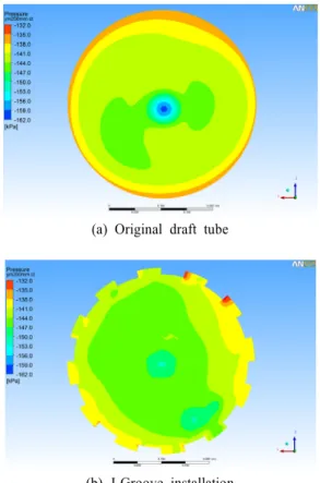
Abstract: Suppression of abnormal flow phenomena in the Francis hydro turbine is very important to improve the turbine performance. Especially, as cavitation and cavitation surge makes serious problems when the turbine is operated in the range of partial flow rate, optimum method of suppressing the abnormal flow characteristics is required necessarily. Moreover, as swirl flow in the draft tube of the Francis turbine decreases pressure at the inlet of the draft tube, suppression of the swirl flow can be an useful method of suppressing the occurrence of cavitation. In order to clarifying the possibility of suppressing the swirl flow by J-Groove in the draft tube, a series of CFD analysis has been conducted in the range of partial load, designed condition and excessive flow rate of a Francis turbine. A kind of J-Groove is designed and applied to the draft tube of the Francis hydro turbine model. The pressure contours, circumferential velocity vectors and vortex core regions in the draft tube are compared by the conditions with or without J-Groove.
In addition, a group of data about the velocity in the draft is presented to show the influence of J-Groove.
Key w ords: Francis hydro turbine, Swirl flow, J-Groove, Draft tube, Performance
†
Corresponding author (Department of Mechanical Engineering, Mokpo National University, E-mail: [email protected], Tel: 061-450-2419)
1 Graduated School, Mokpo National University, E-mail: [email protected], Tel: 061-450-2419 2 Department of Thermal Engineering, Tsinghua University, E-mail: [email protected]
Nomenclatur
D outlet
D W L R r N Ave.v θ
H η θ Q
Inlet diameter of draft tube [m]
Outlet diameter of draft tube [m]
Length of draft tube [m]
Depth of J-Groove [m]
Width of J-Groove [m]
Length of J-Groove [m]
Radius of cross section plane [m]
Local radius of test location [m]
Rotating speed [ min -1 ]
Circumferential averaged velocity [m/s]
Effective head [m]
Efficiency
Expansion angle of draft tube [deg.]
Flow rate [m 3 /s]
1. Introduction
Draft tube surge, one-dimensional pressure pulsations in the draft tube of a Francis Turbine, causes electric power fluctuation. It is resulted from a rotating vortex structure, which caused by the unstable swirl flow from the runner outlet into the draft tube[1]. Some studies have been carried out to suppress the pressure pulsations. But conventional methods are complex and difficult to realize in the case of a large size turbine, Therefore, a common and simple method has been required.
To avoid the detrimental effect of swirl flow,
Kurokawa et al[2, 3]. have conducted a series of
experiments and proposed shallow grooves, which
is named as “J-Groove”, mounted on a casing wall
of turbomachinery, to suppress the cavitation to
some extents. On the other hand, recent results of
experiments verified that J-Groove can increase the pressure in the low pressure region by carrying the high pressure fluid to the low pressure region[4].
Previous studies show that the pressure in the draft tube increase from inlet to outlet, which indicated that if the characteristics of J-Groove can applied to the draft tube, suppression of the surge can be achieved.
Susan-Resiga et al. [5] took a deep sight into the vortex in the simplified discharge cone of a Francis Turbine. It is shown that both RSM and RKE (turbulence models they used) lead to similar shape and size of the recirculation bubble, which is developed as a result of the flow deceleration along the axis. In addition, the central recirculation bubble developed as a result of the vortex breakdown, which contributes to the draft tube surge.
There are two main approaches. One is to act on the axial momentum of the flow, such as Falvey et al. [6] filling the stagnant of reverse flow region with a solid body of rotation, Thicke [7] using rather small conical or cylindrical extensions. The second approach is to reduce the swirl intensity in the cone. Nishi et al. [8] proposed fins to hinder the circumferential flow mainly in the neighborhood of the cone wall but it introduces additional losses and it cannot be adjusted with the operating point.
The approach of this study belongs to the second approach based on the experiments of Kurokawa et al.
The purpose of this study is to examine the possibility of suppressing the draft tube surge in the draft tube of a Francis Turbine by using J-Groove without decrease of the turbine efficiency.
There are several factors to be concerned: vortex, circumferential velocity and efficiency et al. First, the performance characteristics of a Francis turbine model are studied. Then the effectiveness of J-Groove on the suppressing the swirl flow in the draft tube is investigated with the variation of guide vane opening.
2. Turbine model and J-Groove configuration
2.1 Turbine modele
Figure 1 shows the schematic view of the Francis turbine model which is used for CFD analysis in this study, whose runner outlet diameter D e is 0.350m. The number of the blades is 17, and that of guide vanes is 16, whose opening varies from 6.9mm (10%) to 37.8mm (54.5%), while it fully opened to 69.4mm (100%).
The rotating speed of runner, effective head and flow rate at the design point are N=900min-1, H=
60.73m and Q= 0.46m3/s, respectively.
Moreover, Table 1 shows cases of CFD analysis by the variation of guide vane angle.
Figure 1: Schematic view of Francis turbine model
Table 1: Cases of CFD analysis by guide vane angle Analysis
case Guide vane angle
[%] Mass flow rate [×10 -2 m 3 /s]
case 1 10.0 15.1
case 2 19.5 27.0
case 3 23.4 30.3
case 4 31.2 10.0
case 5 35.0 44.2
case 6 38.9 46.0
case 7 46.7 56.6
case 8 50.6 59.9
case 9 54.5 62.6
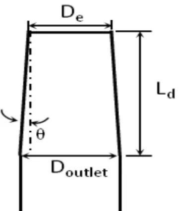
Figure 2: Dimensions of draft tube
2.2 Shape of draft tube
The shape of draft tube is a very important factor to keep the stable flow condition as well as to suppress the occurrence of draft surge at the region. Therefore, many researchers have been tried to design optimum shape of the draft tube.
Kirschner e. al [9] has tried to control vortex with an axial jet in the draft tube. Maiwald e. al[10] has tried to use 13 segments instead of 8 segments in the design of elbow, and build the diffuser with 4 transition and 4 final diffuser segments while the base line is made of 3 transition segments and 1 final segment.
In this study, the shape of draft tube is determined by taking into account of combination with J-Groove. According to the following equation (1), the dimension of expansion angle of draft tube is determined.
L d ≥ 6(D outlet -D e ) (1) where D outlet is diameter of cone base of the draft tube, and D e is the diameter of the inlet of draft tube. And the L d refers to the length of the cone.
As shown in the Figure 2, the angle θ should be less than 4.76 deg. to satisfy the equation (1).
Moreover, previous study results point out that the ideal value of the core angle, which equals to 2θ, is between 5deg. and 9deg. and thus, 3deg. is chosen to the value of θ at last. From the cone
base to the outlet of the draft tube, circular pipe with same diameter is attached.
2.3 Shape of J-Groove
Figure 3 shows the dimensions of J-Groove installed in a draft tube of Francis turbine. In order to suppress the surge caused by the swirl flow in the draft tube, a series of J-Groove are mounted on the wall of the inlet of draft tube with the size 280mm × 45.8mm × 14mm (length L × width W × depth D) while the diameter of inlet of draft tube D e is 350mm.
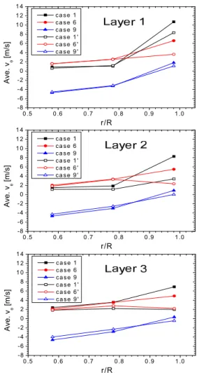
Measuring points in the draft tube are fixed in the directions both by vertical location from the draft tube inlet and radial non-dimensional location from the center of draft tube at each vertical location. Three planes are setup to measure the related data in the draft tube. Y is the vertical axis to measure the locations of the planes from the inlet of the draft tube.
As shown in Figure 4, the vertical measuring locations of the planes (Layer 1, Layer 2 and Layer 3) are Y = - 0.100m, -0.175m and -0.250m, while the value of y axis of the inlet of draft tube is Y =
- 0.075m.
Radial locations are determined by r/R, r is the local radial distance from the center axis to an arbitrary location on the planes, and R is the radius of each section plane cross the draft tube. Three kinds of non-dimensional radial locations are chosen by r/R = 0.58, 0.78 and 0.98.
Figure 3: Dimensions of J-Groove installed in a draft
tube of Francis turbine
Figure 4: Measurement layers and local radius
3. Numerical Methods
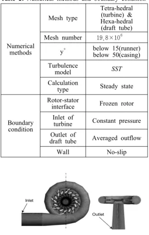
This study employs a commercial code of ANSYS CFX ver.12.0 to conduct CFD analysis [11] and Table 2 shows numerical methods and boundary condition applied to this study.
Table 2: Numerical methods and boundary condition
Numerical methods
Mesh type
Tetra-hedral (turbine) &
Hexa-hedral (draft tube) Mesh number 19.8×10 6
y + below 15(runner) below 50(casing) Turbulence
model SST
Calculation
type Steady state
Boundary condition
Rotor-stator
interface Frozen rotor Inlet of
turbine Constant pressure Outlet of
draft tube Averaged outflow
Wall No-slip
Inlet
Outlet
Figure 5: Numerical mesh of Francis turbine model
As shown in Figure 5, numerical grids of about 19.8×10 6 are adopted for the analysis of the
calculation domain including inlet pipe, casing, runner and draft tube. Relatively dense tetra-hedral grids are applied to the runner. Fine hexahedral numerical grids are employed for the draft tube of the turbine to ensure the high accuracy of calculated results. The value of y+, which means non-dimensional distance from wall, is determined to below 15 for runner and below 50 for the other parts of the turbine in consideration of the shape of turbine passage. SST model is adopted as turbulence model because of its relatively good convergence in the complicated flow field of turbomachinery in comparison with the other models [12]. Constant pressure at the inlet and averaged outflow at the outlet of the calculation domain are the used boundary conditions. All the calculations are conducted under the conditions of steady state.
4. Results and Discussion
4.1 Performance curves
The flow field is investigated when the swirl
enters the draft tube both in the cases of no
J-Groove installation and cases of J-Groove
installation. Figure 6 shows the performance curves
of the Francis Turbine model, including efficiency
curves and mass flow rate curve. The curve without
mark is obtained from experiments without
J-Groove [13]. Efficiency curve of no J-Groove
cases by CFD analysis is marked with ▲, while
the efficiency curve with J-Groove mounted on the
wall of draft tube is marked with △. The
experimental efficiency curve with a little
decrement when the guide vane angle deviates from
designed point (case 6) indicates the Francis turbine
working in good condition. Moreover, two
efficiency curves by experiment and CFD analysis
in case of no J-Groove installation are almost
coincident with small deviation in the ranges of the
partial and excessive flow rates, which makes the
computational results reliable. Moreover, when the
J-Groove is installed, little difference of efficiency is shown in comparison with the case of no J-Groove installation.
0 5 10 15 20 25 30 35 40 45 50 55 60
0 10 20 30 40 50 60 70 80 90 100
0 10 20 30 40 50 60 70 80 90 100
Mas s Flow Rate [ × 10
-2m
3/s ]
Ef fic ien cy [%]
Guide Vane Angle [%]
ηexperiment ηCFD without J-Groove ηCFD withJ-Groove