Shape Effect of Inlet Nozzle and Draft Tube on the Performance and Internal Flow of Cross-Flow Hydro Turbine
Young-Do Choi†․Sung-Woo Son1
(Received Octomber 28, 2011; Revised January 17, 2012; Accepted February 27, 2012)
Abstract:Small hydropower is a reliable energy technology to be considered for providing clean electricity generation. Producing electrical energy by small hydropower is the most efficient contribution to renewable energy. Cross-flow turbine is adopted primarily because of its simple structure and high possibility of applying to small hydropower. The purpose of this study is to investigate the effect of inlet nozzle shape on the performance and internal flow of a cross-flow turbine for small hydropower by CFD analysis. Moreover, the shape effect of draft tube has been investigated according to modified shapes of the length and the diffuse angle. The results show that relatively narrow and converging inlet nozzle shape gives better effect on the performance of the turbine.
Key words:Small hydropower, Cross flow turbine, Inlet nozzle shape, Draft tube, Performance
†Corresponding author (Department of Mechanical Engineering, Mokpo National University, E-mail:[email protected], Tel: 061-450-2419)
1 Graduated School, Department of Mechanical Engineering, Mokpo National University
1. Introduction
Recently, small hydropower attracts attention because of its clean, renewable and abundant energy resources to develop. However, suitable turbine type is not determined yet in the range of small hydropower and it is necessary to study for the effective turbine type. Moreover, relatively high manufacturing cost by the complex structure of the turbine is the highest barrier for developing the small hydropower turbine. Therefore, a cross-flow turbine is adopted because the turbine has relatively simple structure and high possibility of applying to small hydropower.
Previous studies by researchers for the cross-flow turbine have been tried to determine the optimum configuration of the turbine by experimental and numerical methods. Mockmore et al. [1] have used the methods of one-dimensional theoretical analysis
and experiment. Khosrowpanah et al. [2], Fiuzat et al. [3] and Desai et al. [4] have tried experimentally to improve the turbine performance by modifying the shape of flow passages or by applying devices to the turbine. Moreover, Fukutomi et al. [5-8] has demonstrated the effect of component parts of the turbine on the turbine performance by series of studies using experimental and numerical methods. In particular, Choi et al.
[9,10] have shown that air layer effect in the runner passage increases the turbine performance considerably.
In the present study, the relations not only between the performance and internal flow of a cross-flow turbine model, but also between velocity and pressure distributions at the flow passage are examined with the variations of the inlet nozzle shape and, the length and diffuse angle of draft
tube using CFD analysis. Output power evaluated locally from the calculated local torque on the runner blade is analyzed by CFD in order to examine the shape effect on the turbine performance.
2. Turbine model and Numerical Method
2.1 Cross-Flow Hydro Turbine Model
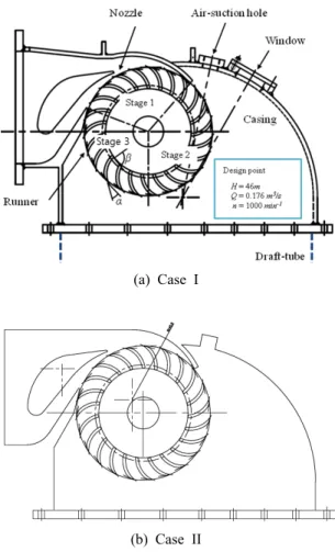
Figure 1 shows the schematic view of a cross-flow turbine models which are used for CFD analysis in this study. Two kinds of inlet nozzle shape (Cases I and II) are adopted to investigate the effect on the turbine performance and internal flow. Internal flow passage of the turbine runner is divided into three stages in order to compare local output power at each local region.
As main purpose of adopting the two nozzle shapes is to check the influence of radius of nozzle curvature on the turbine performance and internal flow, upper wall of nozzle Case I has contracting passage from turbine inlet and becomes expanding passage with circular upper wall from the trailing edge region of guide vane to the nozzle exit.
However, in the case of Case II, straight nozzle upper wall locates from the turbine inlet to the region of runner shaft center horizontally and then, nozzle upper wall has curved passage to the nozzle exit. Nozzle radii of curvature at both cases in the nozzle exit region are 135.5mm (Case I) and 145.5mm (Case II), respectively.
The number of runner blade is Z=23 and the diameter of runner is d=280mm. Inlet and outlet angles of the blade are α=35° and β=100°, respectively. The widths of nozzle, runner and runner chamber are all same, b=135mm. Air suction hole is installed on the top of chamber casing but air is not input for present CFD analysis in order to examine only the hydraulic characteristics of the
turbine. Design points of present test turbine at the best efficient point are H=46m for effective head, Q=0.176m3/s for flow rate and n=1000min-1 for rotational speed. The sections of Stages 1 and 2 in Figure 1(a) are determined by the flow passage of main stream in the turbine.
Figure 2 presents two kinds of the draft tube length (Cases A and B) which are selected by changing the length of draft tube. The draft tube length of Case B is determined to be double the length of Case A.
(a) Case I
(b) Case II
Figure 1: Schematic view of cross-flow hydro turbine models with the variation of inlet guide nozzle shape.
(a) Case A (b) Case B Figure 2: Variation of draft tube length.
Figure 3: Variation of draft tube length.
Figure 3 shows the variation of diffuse angle of draft tube passage. Four kinds of diffuse angle are selected by the variation of the diffuse angle of the draft tube as shown in Figure 3
2.2 Numerical Analysis Method
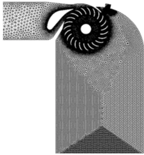
For the numerical analysis of the turbine performance and internal flow by the variation of the turbine structural configuration, a commercial code of ANSYS CFX [11] is adopted. The grid number of 313,648 nodes has been used as shown in Figure 4. Fine tetrahedral-grids are employed to
ensure relatively high accuracy of calculated results for the turbine model.
From the validation test of the numerical model using turbulence models available from the present numerical code [9], k-ω SST model shows reasonable turbine performance and good convergence of calculation. Therefore, k-ω SST model is used for single-phase flow calculation.
Constant pressure at inlet and averaged outflow at outlet are the used boundary conditions.
Table 1 shows calculation conditions for the present turbine model. CFD analysis for the test cases with the variation of turbine structure is conducted under the conditions of steady state and working fluid of water.
Figure 4: Numerical grid system of turbine model (Case I).
Table 1: Calculation conditions.
Boundary conditions
Inlet 466 kPa
Outlet
Mass flow 0.00782 m3/s
(Case I) Turbulence model k-ω SST Calculation type Steady-state
Working fluid Water
3. Results and Discussion
3.1 Output Power by Inlet Nozzle Shape
Figure 5 shows comparison of output power curve by the cases I and II with the variation of flow rate. The calculated result of output power P by Case I with contracting and narrow inlet nozzle shape generates more than that by Case II. This result implies that optimum design of the inlet nozzle shape gives considerable effect on the turbine performance.
3.2 Comparison of Draft Tube Efficiency by Draft Tube Length
Figure 6 shows the comparison of draft tube efficiency ξ by the length of draft tube. Even though Case B has double the draft tube length of Case A, draft tube efficiency, which indicates pressure recovery ratio by the length, does not change so much. This result may be caused by the relatively very high effective head at the inlet in comparison with the recovery head by the draft tube length.
3.3 Comparison of Local Output Power by Diffuse Angle of Draft Tube
Figure 7 presents the divided local output powers at each local region in the turbine runner by extension angle of draft tube. The local output power is evaluated from the calculated local output torque at each region of runner blades. Remarkable output power loss occurs in the recirculation area of Stage 3. According to the extension angle of draft tube, local output power at each region shows somewhat difference. However, the total output power by each extension angle reveals almost same.
It is conjectured that this result is also caused by the relatively very high effective head at the inlet in comparison with the recovery head of draft tube by diffuse angle.
Figure 5: Comparison of output power by inlet nozzle shape.
Figure 6: Comparison of draft tube efficiency by the length of draft tube.
Figure 7: Comparison of output power by diffuse angle of draft tube (Case I).
3.3 Velocity Vectors and Velocity Distribution
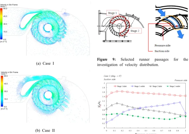
Figure 8 shows velocity vectors in the internal flow field of the turbine model by the variation of inlet nozzle shape. The velocity vectors are expressed using absolute velocity vectors in the flow field of turbine model. As a whole, fluid velocity becomes accelerated along the contracted nozzle passage from the inlet. After passing through the runner blade passage at Stage 1, cross-flow within the runner center gains accelerated velocity once more and then the flow enters into the inlet of Stage 2. Moreover, a large recirculation flow is found in the center region of the runner, especially in the region of Stage 3. The recirculation flow may generate output power loss as examined in Figure 7.
(a) Case I
(b) Case II
Figure 8: Velocity vectors by inlet nozzle shape.
In order to investigate the internal flow in detail, average tangential velocity distribution in the runner blade channel is examined. Figure 9 shows selected local runner passages by each stage for the investigation of velocity distribution.
Figure 10 indicates the average velocity distribution in the turbine blade passages of Case I at the inlet and outlet of Stages 1 and 2 when the diffuse angle of draft tube is 0 degree, which is the case of draft tube is straight vertically. Tangential velocity vθ at the inlet of Stage 1 is relatively higher compared with that of the other region.
However, after passing through the Stage 1, the velocity at the outlet of Stage 1 decreases considerably, which reveals that the angular momentum by fluid velocity is absorbed into the runner blade and changes the angular momentum to
Figure 9: Selected runner passages for the investigation of velocity distribution.
Figure 10: Average velocity distribution at each blade passage.
output power. Tangential velocity at the inlet of Stage 2 is increased when the flow passes through the runner center passage, and then also changes the kinetic energy of the flow at the inlet of Stage 2 to output power of the turbine. Tangential velocity at the outlet of Stage 2 becomes lowered after passing the passages at Stage 2.
3.4 Pressure Contours
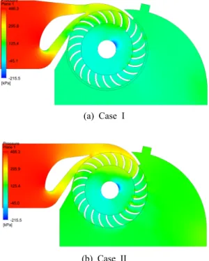
Figure 11 shows static pressure contours in the internal flow field of the turbine model by the variation of inlet nozzle shape. As a whole, turbine inlet pressure decreases along the nozzle passage but the pressure at the nozzle outlet is almost uniform. The fluid pressure passing through the passage of runner blades at Stage 1 drops rapidly.
From this result, it is assumed that the fluid pressure passing through the passage of runner blade is taken by the runner blades and changes the pressure to output power.
(a) Case I
(b) Case II
Figure 11: Pressure contours by inlet nozzle shape.
Comparing pressure contour with the inlet nozzle shape, Case 1 shows lower pressure at the nozzle outlet in comparison with that of Case II. Moreover, pressure at the Stage 1 shows lower pressure by Case I than that of Case II. This result implies that relatively narrow and contracting nozzle passage shape can be useful to the change of effective head to output power at the runner Stage 1.
In addition, relatively low pressure region is located in the center area of the runner, especially in the region of Stage 3, in which a large recirculation flow region is located as shown in Figure 8.
4. Conclusions
The effect of various turbine structures on the performance and internal flow of a cross-flow turbine model are examined by CFD analysis. From the results of the present study, the following conclusions are obtained.
Among the turbine structures examined in this study, present study results show that output power by Case I with contracting and narrow inlet nozzle shape generates more than that by Case II. This result implies that optimum design of the inlet nozzle shape gives considerable effect on the turbine performance.
The length and the diffuse angle of the draft tube in the present turbine model do not influence considerably on the turbine performance. These results may be caused by the relatively very high effective head at the inlet in comparison with the recovery head by the draft tube length.
Recirculation flow in the runner passage may cause output power loss. Therefore, optimized air suction method is required in order to suppress the recirculation region by use of air layer.
References
[1] C. A., Mockmore and F., Merryfield, “The Banki Water Turbine,” no. 25, Engineering Experiment Station, Oregon State Colleg Corvallis, Oregon, 1949.
[2] S., Khosrowpanah, A. A. Fiuzat and M. L., Albertson, “Experimental study of cross-flow turbine,” Journal of Hydraulic Engineering, vol. 114, no. 3, pp. 299-314, 1988.
[3] A. A., Fiuzat and B. P., Akerkar, “Power outputs of two stages of cross-flow turbine,”
Journal of Energy Engineering, vol. 117, no.
2, pp. 57–70, 1991.
[4] V. R., Desai, N. M., Aziz, “An experimental investigation of cross-flow turbine efficiency,”
Journal of Fluids Engineering, vol. 116, pp.
545-550, 1944.
[5] Y., Nakase, J., Fukutomi, T., Watanabe, T.
Suetsugu, T. Kubota and S., Kushimoto, “A study of cross-flow turbine (Effects of Nozzle Shape on Its Performance),” ASME Small Hydro Power Fluid Machinery, pp. 13-18, 1982.
[6] J., Fukutomi, Y. Nakase and T., Watanabe, “A numerical method of free jet from a cross-flow turbine nozzle,” Bulletin of JSME, vol. 28, no.
241, pp. 1436-1440, 1985.
[7] J., Fukutomi, Y. Senoo and Y., Nakase, “A numerical method of flow through a cross-flow runner,” JSME International Journal, Series II, vol. 34, no. 1, pp. 44-51, 1991.
[8] J., Fukutomi, Y., Nakase, M. Ichimiya and H., Ebisu, “Unsteady fluid forces on a blade in a cross-flow turbine,” JSME International Journal, Series B, vol. 38, no. 3, pp. 404-410, 1995.
[9] Y-D., Choi, J-I., Lim, Y-T. Kim and Y-H., Lee, “Performance and internal flow characteristics of a cross-flow hydro turbine by the shape of nozzle and runner blade,” Journal
of Fluid Science and Technology, vol. 3, no.
3, pp. 398-409, 2008.
[10] Y-D., Choi, B-R. Shin and Y-H., Lee, “Air layer effect on the performance improvement of a cross-flow hydro turbine,” Journal of Fluid Machinery, vol. 13, no. 4, pp. 37-44, 2010.
[11] ANSYS Inc., “ANSYS CFX Documentation,”
Ver. 12, http://www.ansys.com, 2010.
Author Profile
Young-Do Choi
He received his B.S. and M.S. degrees from Korea Maritime University, and his Dr.Eng. from Yokohama National University, Japan. Since 2009, he has been a professor at Department of Mechanical Engineering of Mokpo National University. His research interests include new & renewable energy and fluid machinery.
Sung-Woo Son
He received his B.S. and M.S. degrees in Mechanical Engineering from Mokpo National University in 2008 and 2010, respectively. Since 2010, he has been a Ph.D student at Department of Mechanical Engineering of Mokpo National University. His research interests include new & renewable energy and fluid machinery.