파우더 수송시스템의 공기입자 유동 압력강하 특성
Pressure Drop Characteristics of Air Particle Flow in Powder Transport Piping System
김종순
1
, 정성원1
, 권순구1,
박종민1,
최원식1
, 권순홍1*
Jong-Soon Kim 1 , Sung-Won Chung 1 , Soon-Gu Kwon 1 , Jong-Min Park 1 , Won-Sik Choi 1 , Soon-Hong Kwon 1
<Abstract>
The pressure drop characteristics of air particle flow in a powder transport piping system were analyzed in this study. The pressure drop characteristics of air particle flow in the piping system have not well understood due to the complexibility of particle motion mechanism. Particles or powders suspended in the air flow cause the increase of the pressure drop and affect directly transport efficiency. In this study, the pressure drop in a powder transport piping system was analyzed with interactions of air flow and particle motion in straight and curved pipes. The total pressure drop increased with pipe length, mixture ratio, and friction factor of particles because of increased friction loss of air and particles in the piping system. For the coal powders of 74 ㎛size and powder-to-air mass mixture ratio of 0.667, the total pressure drop under the consideration of powders and air flow was calculated as much as 30%
higher than that air flow only.
Keywords : Pressure Drop, Air-Particle Flow, Particle Motion, Transport Piping System
1*정회원, 교신저자, 부산대학교 바이오산업기계공학과, 교수
경남 밀양시 삼랑진읍 삼랑진로 1268-50 우편번호 50463
(E-mail: [email protected] )
1*Corresponding Author, Professor, Dept. of Bio-Industrial Machinery Eng., Pusan National Univ.,
Miryang 50463
REPUBLIC OF KOREA
(E-mail: [email protected] )
1. Introduction
This study analyzed the pressure drop characteristics for the air particle flow in a powder transport piping system, and total pressure drop was analyzed through the pressure drop analysis based on pipe length, particle mixture ratio, and particle friction factor. This study considered coal particle motion that dominantly influences the pressure drop along with the air flow that causes pressure drop. This study will contribute to the design of optimal gas particle transport systems with high transport efficiency and to the establishment of technical analysis of pressure drop by particle in the gas particle transport piping system.
Coal, cement, chemicals, and cereals are granulated in many industrial processes involving particle transport for ease of transport and suitability of the process, as a consequence, many studies about two phase flow of gas and particle in the pipeline have been conducted.
Studies on the analysis of gas particle transport systems are required, because particle transport efficiency is connected with production efficiency, quality improvement, and profitability in thermal power plants, cement industry, and milling industry. Particle transport in the air particle flow is two-phase flow, which has a problem that pressure drop lowers transport efficiency. The pressure drop is caused by geometric properties of the pipe (i.e. straight or curved shapes, the number of pipes including couple ring, length, and angle of the pipe), air
flow, and suspended particle motion.
Total pressure drop in the pipeline is caused by air flow and suspended particle motion, but it is dominantly influenced by the suspended particle motion. However, there is little research on the pressure drop caused by the characteristics of various pipelines and air particle flow. Therefore, gas-particle transport in the pipeline is analyzed by the pressure drop that considered air flow only, as a result, optimal transport conditions are not determined. Thus, pressure drop should be analyzed considering suspended particle motion in the pipeline to improve transport efficiency.
The pressure drop by air flow in a powder transport piping system is caused by acceleration force of the air and frictional force on inner pipe. Precise pressure drop cannot be calculated due to the influence of many factors such as size, shape, density of the particle in the air particle flow of the pipeline, and most analyses rely on empirical formulas. Mixture flow pattern of air and particle is important among the factors that affect pressure drop in the air particle flow of the pipeline, and the main factor that determines this is mass mixture ratio of the particle [1-3] .
Mass mixture ratio of the particle in an air coal conveying system in thermal power plants shows dilute flow pattern that is less than 10, and typical mass mixture ratio is in a range of 0.4∼1.0 [1-3] .
Many studies about analysis model relating
pressure drop for the air particle flow have
been conducted, however, good results are observed under limited conditions based on each characteristic of the analysis model.
There is little research on pressure drop analysis based on the analysis condition and factor, therefore, the quantitative analysis for that should be conducted.
2. Pressure drop mechanism for the air particle system.
2.1 Pressure drop theory
Particle transport is regarded as the process of consuming energy of air flow in the form of pressure, and total pressure drop for the air particle flow in a straight pipeline of certain length (ΔP T )is the sum of the pressure drop caused by the air flow (ΔPa), pressure drop for accelerating powdered or granular particles to a certain speed (ΔP SG ), and pressure drop applied to transport the accelerated particle at a constant rate (Δ PS)(equation(1) [3] .
(1)
Each pressure drop from equation (1) can be represented as equation (2) by using Fanning equation.
(2)
Where,
: Pressure drop
: Pipe friction factor for air or particle
: Pipe length
: Pipe diameter
: density
: velocity
2.2 Pressure drop mechanism by particle motion in the pipeline
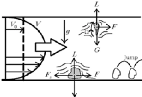
Analysis of the pressure drop mechanism due to particles in the pipeline is significantly influenced by the particle motion mechanism that causes pressure drop. Velocity changed depending on the radius in the flow of the pipeline, and velocity of the pipe wall changed significantly with turbulence. Therefore, the velocity of the particle mixed in the air flow differred according to positions from the pipe wall, and particle motion had a very complex mechanism.
Figure 1 shows the transport mechanism of the particles passing through the pipeline.
During the particle transport, particles were attached to the inner surface of the pipeline, or the particles became obstacles that resulting in pressure drop, and forces that contributed to this mechanism were the gravity (G), lift (L), pressure (F), and friction (Fs)of the particles [4] .
Figure 2 shows the aerodynamic forces and
streamlines acting on a particle, and the
particle began to move with sliding slowly
when the pressure of the particle by the
streamline near the bottom of the pipe (F)
overcame the friction of the particle as flow velocity increasing. As the flow velocity increased, lift force increased and eventually overcame the gravity of the particle. And then the particle jumped into the streamline from the bottom of the pipe. The particle followed the streamline axis unstably and dropped to the bottom, and this jump was repeated.
When the flow velocity increased more, turbulent flow was generated [4] .
Figure 3 represents the trajectory of particles in the turbulent flow of air, and each particle moved with small vibration. Circulating flow was generated in the particles themselves due to vortex generated in flows past a particle.
And streamline was combined and Magnus effect that forces acting at right angles to the flow was occurred. The particles collided with the inner wall of the pipe due to the forces acting at right angles to the direction of motion, and the friction consumed the part of kinetic energy.
Fig. 1. Transport mechanism of particles in a pipe
Fig. 2. Aerodynamic forces and streamlines acting on a particle
Fig. 3. Trajectory of particles in turbulent flow of air
It was difficult to investigate all the particle group in the analysis of the pressure drop mechanism due to each particle motion that changed according to the radial position inside the pipe. Therefore, it was calculated by obtaining average motion of the entire particle group. Air and particle were interpreted as special fluids, and the pressure drop was calculated by identifying each fluid movement.
The analysis of the pressure drop should
consider following: Flow pattern of the
particle group influenced the analysis of the
pressure drop due to the particle motion
inside the pipe, and the flow pattern of the
particle group was determined by the mixture
ratio of the particle and air [4] .
3. Pressure drop for the air-particle flow in the powder transport piping system
3.1 Pressure drop by air flow
The pressure drop due to the air flow in the powder transport piping system was occurred by acceleration of the air and friction inside the pipe. This study analyzed the pressure drop by air flow as a sum of pressure drop of straight and curved pipelines caused by the pipe friction under the assumption that accelerated air entered the pipeline and kept a constant velocity inside the pipe [5,6] .
Darcy friction factor formulae were used as shown in equations (3) and (4) to analyze the pressure drop by air flow in the straight pipe (horizontal and vertical pipes), and main factors that influenced the pressure drop were pipe friction factor (f), velocity (V), and the ratio of the diameter and length of the pipe (L/D) [5,6] .
(3)
∣
(4)
log
(5)
Where,
: Pressure drop of the horizontal pipe
∣ : Pressure drop of the vertical pipe
: flow velocity
: Pipe friction factor of air flow calculated by Cole brook equation (5)
: Height difference of the two points
: Surface roughness of the internal pipe
: Acceleration of gravity
: Reynolds number
The pressure drop of the curved pipe was analyzed using empirical equations of the flow conditions because of the analysis difficulty of factors such as turbulent flow, secondary flow depending on the radius of curvature, the ratio of the pipe radius and radius of curvature (R/r), and the angle of the curved pipe (θ). This study analyzed the pressure drop of the curved pipe using Ito equations with which Reynolds number (Re) satisfies the turbulent flow conditions of 105grade. Loss coefficient(K θ )was calculated after calculating correction factor based on angle of the curve pipe (C θ ) and loss coefficient of the curved pipe (K 90° ) with in the Reynolds number, and the pressure drop of the curved pipe was calculated using Darcy’s formula [5,6] .
(6)
(7)
×
×
×
(8)
Where,
: Pressure drop of the
curved pipe
: Loss coefficient of the curved pipe at a 90° angle curve
: Correction factor based on the angle of the curve pipe
: Loss coefficient of the curved pipe
: Angle of the curved pipe
Loss coefficient of the curved pipe at a 90 ° angle curve was calculated based on the range of the Reynolds number as shown in equations (9) and (10).
①Re⋅(r/R) 2 <91,
∙ ∙ ∙
(9)
②Re⋅(r/R) 2 >91,
∙ ∙ ∙
∙
(10)
Where,
: Radius of the pipe
: Bending radius of the curved pipe
: Friction factor by Ito equation
: Experimental factors based on angle
∙
∙
(11)
∙
(12)
Thus, total pressure drop by air flow of the powder transport piping system was calculated as a sum of pressure drops of the straight pipe and curved pipe.
3.2 Pressure drop by particle motion
The pressure drop by particle motion was analyzed by a theory which was derived in terms of energy of the two-phase air-particle flow. The causes to generate the pressure drop by particle motion were acceleration force of the particle and frictional force, buoyant force, and lifting force. This study analyzed the pressure drop considering only the constant speed section (frictional force, buoyant force, and lifting force) except acceleration force.
The friction between air and pipe wall was considered to be the same as air flow only.A decrease in the pipe cross-section by the particle was ignored, and friction loss between particle and pipe wall was analyzed under the assumption that the particle suspended within the pipe was considered as a special fluid [7] .
The pressure drop by particle friction force was calculated using Darcy’s formula as shown in equation (13).
for
(13)
Where,:
for Pressure drop by particle friction force
: Specific weight of the particle
: Particle velocity
: Acceleration of gravity
: Pipe friction factor of the particles
(Sum of the friction loss of the individual
particles)
When particles flowed uniformly, the particles constantly contacted with the front pipe wall. Therefore, λs was assumed to be a special fluid, and this study analyzed the pressure drop by particle friction force using Mathur and Klinzing’s particle friction coefficient modeling(14).
(14)
Where, : Pipe diameter
: Gas velocity
: Particle diameter
: Particle density
Bauoyant force and lifting force (floatation) also generated pressure drop, and they were influenced by several factors such as particle type, shape, and specific weight. Floatation is the force required to maintain a particle in a present position, and lifting force is the force required to lift a particle in an uprising pipe or inclined pipe. Only buoyant force was considered in the horizontal pipe for the lifting of particles, but in the vertical pipe both lifting force and buoyant force were considered for lifting particles.
Figure 4 shows forces acting on solid particles in air flow of horizontal pipe, and flotation energy (buoyant energy and lifting energy) can be calculated from the forces acting on the particles.
Based on the flow direction of air flow, particle force per unit was divided by particle velocity
and represented as /
considering all particles in the pipe under the conditions of pipe length L and rising height H. Particle force per unit that acted on the pipe length L was represented as L/
.When this force acted in the direction of gravity, considering particle gravity settling velocity, particle force per unit that acted on the pipe length L can be converted to the energy acting on the distance per unit time in the direction of gravity.
Particles
Gs(N/s) Flow Direction
→ → us(m/s)
↓Gravity
Fig. 4. Forces acting on solid particles in the air flow
This energy acted as pressure drop energy, and the pressure drop energy (ΔP s, buoyant force )by buoyant force per unit volume of air ( ) was represented as equation(15).
for
∙
∙
(15)
The force that lifted the particles to a certain height H was converted to the energy, and the pressure drop energy (ΔP s, lifting force )by lifting force per unit volume of air was represented as equation(16).
for
(16)
The pressure drop by particle floatation was analyzed as a sum of pressure drop by particle buoyant force (15) and particle lifting force.
Pressure drop by particle motion in the coal transport piping system (ΔP s ) was analyzed as a sum of pressure drop by friction force, buoyant force, and lifting force(17).
(17)
Where,
: Ratio of air velocity (
) and particle velocity(
)
Mixture ratio (m) of transport weight of air ( ) and transport weight of particle ( ) was the main factor that affected the pressure drop in the air-particle flow, and equation (17) can be represented by considering the mixture ratio as equation(18).
(18)
Curved pipe is used widely to minimize the transport distance. The fluid near the pipe wall flowed adhering to the wall surface because of inertia, but the fluid in the center line did not adhere to the wall. Therefore, the fluid in the curved pipe flowed under the action of centrifugal force, but the fluid near the center of the cross section of the pipe generated a swirling vortex of second flow by receiving force from outward direction. Due
to the influence of this phenomenon, the pressure drop of the curved pipe was higher than the one of the straight pipe. Research done by Schuchart (1969), Spronson (1973), and Morikawa et al. (1978) presented models for calculation of the pressure drop by particle in the curved pipe, however, the models are suitable for large particles having a particle size of 1∼2mm, which was difficult to apply in this study with particle having a size of 74
㎛. Thus, this study analyzed the pressure drop by converting the curved pipe into the straight pipe having the same pressure drop and same length.
3.3 Total pressure drop for the air particle flow
Total pressure drop (ΔP T ) of air-particle flow in the coal transport piping system was represented as a sum of the pressure drop by air flow (3.1) and pressure drop by particle motion (3.2) as shown in equation (19).
(19)
4. Analysis of the pressure drop in the powder transport piping system and results
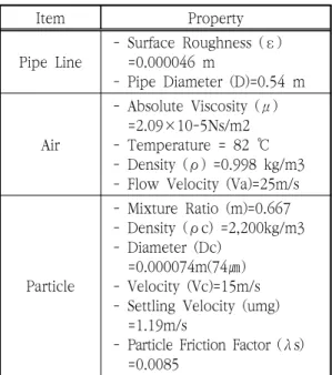
Table 1 presents the input data for the pressure drop analysis of the air particle flow in pipelines, and it shows the properties of the pipeline, air, and particles. At the temperature of 82˚C, diameter of the pipeline (D) of 0.54 m, air velocity (
) of 25m/s, mixture ratio (m) of 0.667, and coal diameter ( ) of 74 ㎛ were used as default input values under the same conditions with the coal pipeline in actual thermal power plant. Particle velocity in the air flow was 0.6 times of air particle, and coal particle velocity was calculated as 15 m/s.
Gravity settling velocity
was calculated with equation (20) because Reynolds number
was 53 which was larger than 1 and particle diameter was larger than 1 ㎛.
(20)
Where, : Drag coefficient of the particles
: Gas density
The drag coefficient of the particles ( ) was calculated with equation (21) 9) .
(21)
Table 2 provides the input data for the pressure drop analysis of air-particle flow in the coal piping system, and the piping system consisted of straight pipe and curved pipe. The length of the pipe was provided for the straight pipe; angle, number, and the ratio of radius of curvature and pipe radius (R/r) were provided for the curved pipe.
Total pressure drop in the pipeline was calculated as a sum of pressure drops by air flow and particle motion for the straight and curved pipes.
Item Property
Pipe Line
- Surface Roughness (ε) =0.000046 m
- Pipe Diameter (D)=0.54 m
Air
- Absolute Viscosity (μ) =2.09×10⁻⁵Ns/m2 - Temperature = 82 ℃ - Density (ρ) =0.998 kg/m3 - Flow Velocity (Va)=25m/s
Particle
- Mixture Ratio (m)=0.667 - Density (ρc) =2,200kg/m3 - Diameter (Dc)
=0.000074m(74㎛) - Velocity (Vc)=15m/s - Settling Velocity (umg) =1.19m/s
- Particle Friction Factor (λs) =0.0085
Table 1. Properties for the pressure drop analysis of the air particle flow in the pipe lines
Figure 5 shows the pressure drop ratio
based on particle friction factor (
)and
mixture ratio (m) under the conditions of
pipe diameter (D) of 0.54 m, air velocity (
)
of 25m/s, particle flow velocity of 15m/s, and
coal particle size of 74
. Friction increased with increasing mixture ratio, as a result, pressure drop ratio increased. Increased particle friction factor raised pressure drop ratio because of the particle kinetic energy loss caused by increased friction between particles and the internal surface of the pipe.
When transporting 74
particle size of coal under the conditions of pipe diameter of 0.54 m, air velocity of 25 m/s, mixture ratio of 2, and friction factor of 0.0085, total pressure drop increased by twice compared to the pressure drop by air flow.
Fig. 5. Analysis results of the pressure drop as a function of mixture ratio and particle friction factor for the air particle flow in the transport piping system
Fig. 6. Comparison of total pressure drop and pressure for air flow only as a function of pipe length for the air particle flow in the transport piping system
Figure 6 shows the analysis results of pressure drops based on the length of straight pipe. When transporting 74
particle size of coal under the conditions of mixture ratio of 0.667, friction factor of 0.0085, air velocity of 25 m/s, and the pipe diameter of 0.54 m, pressure drop increased with increasing length of pipe and increasing friction between air and particles. The pressure drop by air flow increased by 6.74 times of the length of the straight pipe. Total pressure drop of the pipeline increased by 8.84 times of the length of the straight pipe, and it increased by 1.31 times compared to the pressure drop by air flow. The results showed that pressure drop showed a constant proportional increase with the length of the straight pipe in the air-particle flow, and they can be utilized as the basis for the pressure drop analysis.
The pressure drop was analyzed in four different pipes with the pipe diameter of 0.54m, the air velocity of 25m/s, and the
Pipe Specification
Straight Pipe Length (m) 50 Curved Pipe
Number 1
Angle (
) 45R/r 4
Note: R/r = Ratio of Radius of Curvature (R) to Pipe Radius (r)
Table 2. Input data for the pressure drop analysis in the transport piping system
mixing ratio of 0.667 (Table 4). The pressure drop was caused by air flow and particle motion. As the length of the straight pipe and the angle and the number of the curved pipe increase, the pressure drop from air flow and particle motion increases. It results in the increase of the total pressure drop in the piping system as well. In other words, at the straight pipe the pressure drop was large at the longer pipe based on Darcy’s equation.
In addition, a curve in a pipe induces a large friction loss between air and particles, due to flow separation at the walls and a swirling secondary flow arising from the centripetal acceleration. As a result, its pressure drop is much larger than the one at the equivalent length of a straight pipe.
Pipe No.
Pressure Drop for Air Flow
Pressure Drop for
Particles Motion ΔPt (Pa) α ΔPa
(Pa) ΔPs
(Pa) ΔPc
(Pa) ΔPp
(Pa) ΔPs
(Pa) ΔPc
(Pa)
1 365.0 336.8 28.3 113.9 105.1 8.8 478.9 1.3 2 673.7 606.2 67.5 210.1 189.1 21.0 883.8 1.3 3 627.1 538.8 88.2 195.6 168.1 27.5 822.7 1.3 4 1,146.3 1,010.3 135.9 357.6 315.2 42.4 1,503.8 1.3 Table 3. Analysis results of the pressure drop as
a function of pipe form for the air particle flow in coal piping system.
5. Conclusion
The pressure drop characteristics of air particle flow in a powder transport piping system were
analyzed in this study. The pressure drop analysis was conducted by considering air flow and particle motion based on mixture ratio, particle friction factor, length of the pipe in the straight and curved pipes. When the mixture ratio and particle friction factor increased, the friction of pipe by air flow and particle motion increased, which resulted in large increase of total pressure drop compared to the one by air flow. When transporting 74 ㎛ particle size of powder under the conditions of mixture ratio of 2 and friction factor of 0.0085, the total pressure drop was increased by twice compared to the pressure drop by air flow. From the results of pressure drops based on the length of straight pipe, the pressure drop increased with increasing length of pipe and increasing friction between air and particles.
When transporting 74 ㎛ particle size of powder under the conditions of mixture ratio of 0.667 and friction factor of 0.0085, the total pressure drop of the pipeline was increased by 8.84 times of the length of the straight pipe. In addition, it was increased by 1.31 times compared to the pressure drop by air flow. This study developed an analysis program for pressure drop of the air particle flow in a powder transport piping system, and the results can be utilized for the optimal design of various powder transport piping systems.
Acknowlegement
This work was supported by a 2-Year
Research Grant of Pusan National University.
Reference