http://dx.doi.org/10.7839/ksfc.2016.13.4.031
A Study on Energy Saving of IMV Circuit using Pressure Feedback
Hyoung Gyu Park 1 , Syed Abu Nahian 1 and Kyoung Kwan Anh 2*
Received: 29 Jan. 2016, Revised: 03 Aug. 2016, Accepted: 14 Oct. 2016
Key Words:Hydraulic actuator; Independent metering valve; Energy saving; Pressure feedback control.
Abstract: In recent hydraulic actuation systems, conventional hydraulic spool valves with pressure compensators are becoming less popular, after the introduction of the independent metering concept for valves. Within this concept, four valves are needed for actuating a single cylinder. Subsequently, this increases the freedom of controlling both chamber pressures of the cylinder, and it then provides for electronically-controlled pressure compensation facilities. Additionally, this has the potential to save valuable energy. The primary focus of this paper is to develop a new generation of hydraulic circuits using the independent metering valve (IMV). This configuration can function well as a conventional IMV circuit while providing better pressure control. We first describe the working principles of five distinct modes of the proposed IMV system. Then, mathematical models for each working mode are presented. Finally, we present numerical simulations that have been carried out to evaluate the system performance, in comparison with that of the conventional IMV configuration. The simulation results demonstrate that the performance of the new IMV configuration is superior to the conventional IMV system in terms of energy savings.
* Corresponding author: [email protected]
1 Graduate school of Mechanical and Automotive Engineering, University of Ulsan, Ulsan 680-749, Korea.
E-mail: [email protected]
2 Graduate school of Mechanical and Automotive Engineering, University of Ulsan, Ulsan 680-749, Korea.
Copyright Ⓒ 2016, KSFC
This is an Open-Access article distributed under the terms of the Creative Commons Attribution Non-Commercial License(http://
creativecommons.org/licenses/by-nc/3.0) which permits unrestricted non-commercial use, distribution, and reproduction in any medium, provided the original work is properly cited.
1. Introduction
Hydraulic systems are usually used on a large scale throughout the industry for its high power to size ratio.
They are widely used in excavation, construction and agriculture systems, etc. In hydraulic actuation systems, motion controlling is one of the most important tasks.
Generally, the conventional hydraulic system is controlled by direct-acting, pilot-controlled, or electro hydraulically-controlled directional spool valve.
However, conventional electro-hydraulics typically increase machine costs, have difficulty controlling systems which contain control valves. High performance of a hydraulic system can be obtained by using a typical four-way proportional directional valve.[1][13]
Hence, the reference papers shown that the valve can
meet high performance requirements of hydraulic
systems. However, it has one degree of freedom. It
depends on metering in and metering out opening area
which is the position of the spool and only one
chamber’s pressure can be controlled. Hence it cannot
provide precise motion control while controlling
pressure in both actuator chambers. This means that its
potential for energy savings is low. Moreover, almost
traditional hydraulic systems that work this kind of
technology only sense the pressure in the inlet chamber
of the actuator, while being unknown to the pressure in
the other chamber and it uses pressure compensators to
keep a constant pressure margin across the spool valve
inlet and thus achieve a linear relationship between the valve opening and flow. The technical solution is that the Pressure Compensated Load Sense (PCLS) systems are blind to the pressure in the return chamber and it will drive the supply pressure high even when not needed, which means more energy consumption.
Therefore, if the drawback of typical four way directional control valves is broken then the flexibility of the valve could be drastically increased, making the way for significant improvements in hydraulic efficiency in [2]. The technique of breaking the mechanical linkage between the meter-in and meter-out orifice is well known and has been used in heavy industrial applications for several years. The technology is called the independent metering hydraulic circuit. Nowadays, hydraulic industry has a common trend how to design a valve that is applicable to various systems.[3]
In this trend, to achieve a linear relationship between the valve opening and flow, a constant pressure margin across the spool valve inlet and outlet is required. To solve this problem, pressure compensators are used in [4]. But the traditional pressure compensated load sensing system has a major disadvantage due to its blindness to pressure in the return chamber. This can be a major reason of inefficiency in [5]. Notwithstanding the smallest improvement in efficiency can offer a significant economic impact on the total cost. So energy saving on hydraulic actuation systems is one of the most important concerns of current researches. To achieve the desired performance in terms of cost and energy saving, independent metering valves were introduced for achieving higher system efficiency. Some researchers were able to achieve independent metering by adding an extra control dimension in hydraulic valves. This idea has been used for several years in the hydraulic industry. By using two conventional proportional directional control valves, one for meter in control and another one for the meter out control, partial independent metering can be achieved in [6].
Nevertheless, replacing one valve with two same kinds of valves is an expensive solution and also, full independent metering cannot be achieved.
Replacing the typical four-way servo valve with
four-poppet type valves that can be controlled separately is another solution. Kramer et. al. in [7] developed a system and a control method to achieve independent metering. The authors proved that it has potential to control the pressure of both cylinder chambers. HUSCO in [8] also developed this kind of valve which is called electro-hydraulic poppet valve (EHPV). Jansson et al.
in [9] demonstrated another hydraulic system using four valves with independent metering. Using this four-valve configuration, each two valves are actuated regarding a specific function, allows achieving independent metering and energy regeneration. Amir Shenouda and Tien in [10] and [14] developed a quasi-static control system to achieve independent metering for four-valve assembly and then verified it by simulations as well as experiments. This system has the potential of reducing flow requirement from the pump so that, valuable energy can be saved. Flow requirement is minimized by recirculating fluid from one chamber to another chamber that is referred as a regenerative flow. Tabor in [11]
and [12] developed mathematical models of a hydraulic actuator using four-valve independent metering. And this model was validated by experiments.
In this paper, a new generation of independent metering hydraulic circuit is proposed. Three EHPV valves and a simple directional control valve are used to reduce the system cost and energy consumption. This configuration has potential to overcome the control difficulties of the typical four-valve circuits while it provides the same number of metering modes.
Moreover, regenerative flow and high pressure flow
from the pump do not connect directly so it is possible
to save more energy by flow regeneration. The force
feedback technique is used to develop the mathematical
modeling to make this system capable of reacting faster
and more accurately even facing with disturbances. The
control equations for each metering mode are developed
in such a way that these can be expressed as a simple
orifice equation based on equivalent valve conductance
and equivalent pressure concepts. Then equation for
determining the supply pressure is also derived. The
remained things are then organized as follows: Section
2 gives a brief overview of the conventional
independent metering hydraulic circuit; the concept and working principle of the new configuration is introduced in section 3 and mathematic model developed for each metering mode of this circuit is derived in Section 4;
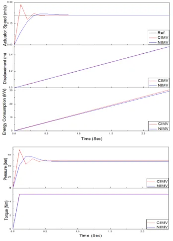
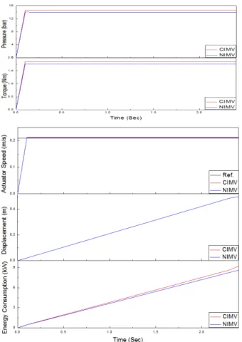
Simulations are carried out in Section 5 to investigate the performance of the proposed system in comparison with the conventional IMV system; Finally, concluding remarks are presented in Section 6.
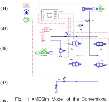
2. Conventional Independent Metering with Four Valves
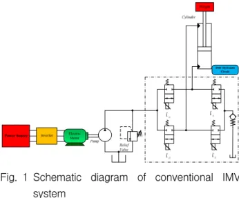
The conventional IVM (CIMV) circuit mainly includes four electrohydraulic poppet valves (EHP) and one check valve. By using the typical independent metering concept, the four-valve configuration with five distinct metering modes in [12], [13] and [14]
can drive the cylinder to the desired trajectories. It allows energy regeneration and reduces the required pump energy subsequently, saves valuable energy. In this concept, two valves are used to connect between two ports of the cylinder to the supply line, the other ones are to connect to the return line as depicted in Fig. 1.The five working modes of this system can be listed down as
Power Extension Mode (PE) Power Retraction Mode (PR)
High Side Regeneration Extension Mode (HSRE) Low Side Regeneration Extension Mode (LSRE) Low Side Regeneration Retraction Mode (LSRR)
K
b tK
a tK
saK
sbFig. 1 Schematic diagram of conventional IMV system
The first two modes, PE and PR, are conceptually same as the operation of a cylinder driven by a conventional proportional directional control valve. But these modes have a benefit of independent metering which cannot be achieved by the directional control valve. During operations with powered load, the directional control valve causes energy loss due to the valve restriction in the return line. This drawback can be minimized by independent metering concept. In HSRE mode, the potential to save energy can be achieved by recirculating the flow to the high pressure side, which could not be obtained by using the directional control valve. On the contrary, the other two modes, LSRE and LSRR, recirculates the flow to the low pressure side and then, save additionally energy. In both modes, the check valve is used to build up necessary pressure for performing regenerative actions.
However, the use of this check valve causes power loss.
Besides, controlling these four valves to obtain the optimal performance is also difficult due to increase of nonlinearities of the hydraulic system. In addition, energy saving is lower than expected because of direct connection in between recirculating flow and supply flow as a result pressure difference is low. Finally, the use of four electrohydraulic poppet valves (EHP) increases the system cost.
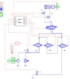
3. New Independent Metering Configuration
To overcome the shortcoming of conventional independent metering (CIMV), the new configuration of NIMV is proposed with three EHP valves along with one directional control valve to perform all modes that are available in the CIMV configuration. The NIMV schematic is shown in Fig. 2. Here, three EHP valves allow to obtain independent metering and the directional control valve is for getting the same number of working modes as the CIMV configuration. Reduction of the number of working valves indicate downward slope of cost. Subsequently, controlling the NIMV system is easier than the conventional one.
The five distinct metering modes of the NIMV are
described as follows.
Power Source Electric Motor Inverter
Pump Relief
Valve
Cylinder
IMV Hydraulic Circuit
K
a bK
saK
sbK
spWeight
IMV Hydraulic Circuit
Fig. 2 Schematic diagram of proposed IMV system
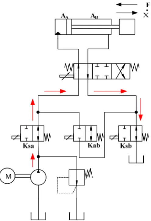
3.1 Power Extension Mode (PE)
Regarding the hydraulic actuator controlled by the CIMV, this mode is not conceptually different and described in Fig. 3 (the arrows showing the direction of force and velocities). The directional control valve is energized on the left side. The supply oil travels through the SA valve into the head side of the cylinder and the oil forced out from the rod side travels through the SB valve to the return line. In this configuration, SA and SB can be controlled independently same as in the PE mode of CIMV. Thus flow to the tank does not need to be always restricted. So if an overrunning load is not present, the outlet valve can be fully opened. For preventing cavitation problem, the NIMV system can
Fig. 3 Power Extension Mode (PE)
reduce selectively the outlet valve coefficient. In addition, a fixed margin pressure does not need to be maintained across the active valves.
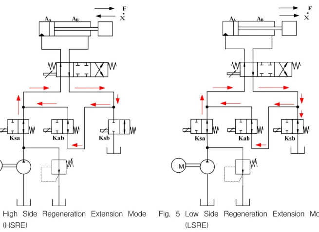
3.2 High Side Regeneration Extension Mode (HSRE)
High side regeneration extension mode is quite similar to power extension mode except this mode has energy regenerative capacity. A schematic that describes this mode is shown in Fig. 4. In this mode, the directional control valve is energized on the left side and, the other two valves: SA and AB are employed.
The supply oil flows through the SA valve to the head side of the cylinder and consequently, the pressurized oil from the rod side of the cylinder is recirculated through the AB valve to the pump high pressure side.
High side refers to the high pressure or pump side of the assembly and, regeneration refers to the oil transferring from one side of the actuator to the other side. To reduce the line losses, it is better to design the circuit with putting the valve physically closer to the respective actuator.
However, due to the difference between areas of
chambers, A and B, the flow from chamber B is less
than the flow needed for chamber A to obtain certain
velocity. Hence, an additional oil amount is needed
from the pump to move the actuator. By doing the
recirculation, this HSRE mode has the potential to save
energy. By using the same amount of oil compare to
the conventional proportional directional control valve, it
is possible to obtain higher speed if the load is not so
high. The HSRE mode is more suitable for a multi
actuator system that one actuator has to move large
load thus demand high pressure and another may be
moving smaller load. As a high pressure is already
available for operating former actuator from pump
supply, it would save oil flow if latter actuator is
operated by HSRE mode because this mode has
potential to save oil flow by recirculating. As a result,
it will minimize the total energy consumption. Besides,
the recirculating flow is higher than that of the CIMV
configuration due to the higher-pressure difference
between the recirculating flow and the supply flow.
Fig. 4 High Side Regeneration Extension Mode (HSRE)
3.3 Low Side Regeneration Extension Mode (LSRE) Another regenerative mode can be achieved by this NIMV assembly is low side regeneration extension mode. Fig. 5 displays the operating concept of this mode. This mode is used to handle over running load during lowering. Same as the HSRE, the directional control valve is energized on the left side while the two valves, SA and AB are used to perform this operation.
During the actuator extension, the low side generation is performed by circulating the low pressure oil at the rod chamber of the cylinder to its head chamber through valve AB. As discussed in the HSRE mode, the additional flow needs to be supplied by the pump to fulfill the flow requirement due to the cylinder chamber volume difference. In the conventional actuator using solenoid controlled valve, an outlet restriction is added in the design of the spool valve to prevent the system from falling at uncontrollable speeds, which causes energy loss. This loss can be minimized by using the NIMV with the LSRE mode. Moreover comparing with the CIMV, there is no check valve needed for pressure build up. Therefore, this configuration has the potential to save more energy.
Fig. 5 Low Side Regeneration Extension Mode (LSRE)
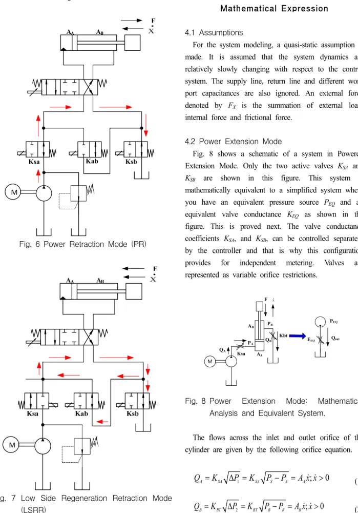
3.4 Power Retraction Mode (PR)
This working mode is also conceptually same as the PR of CIMV. Fig 6 displays the NIVM operation in PR mode. Firstly, the directional control valve is energized on the right side. Oil flow from the pump enters into the rod side of the actuator thorough the SA valve and then, the oil in the head side is forced out to the tank through the SB valve. These two valves can be independently controlled. Therefore in this mode, the same controlling capability is available as the power extension mode.
3.5 Low Side Regeneration Retraction Mode (LSRR) This mode is applicable for overrunning load, which, for example, happens when lowering a load with gravity assistance. The principle is same as the LSRE mode except the oil flow direction. Here, the directional control valve is energized on the right side as in Fig. 7.
The oil flow coming out from the head chamber is
circulated through valve AB into the rod chamber to
cause the piston to retract. The extra oil flow due to
the chamber volume difference then goes to tank
through valve SB. This mode has high potential for
saving energy because no pump flow is needed. Hence, it is called low side regeneration retraction mode.
M
F A A A B
Ksa Kab Ksb
Fig. 6 Power Retraction Mode (PR)
Fig. 7 Low Side Regeneration Retraction Mode (LSRR)
4. Quasi-static System Modeling of Independent Metering Valve with
Mathematical Expression
4.1 Assumptions
For the system modeling, a quasi-static assumption is made. It is assumed that the system dynamics are relatively slowly changing with respect to the control system. The supply line, return line and different work port capacitances are also ignored. An external force denoted by F X is the summation of external load, internal force and frictional force.
4.2 Power Extension Mode
Fig. 8 shows a schematic of a system in Powered Extension Mode. Only the two active valves K SA and K SB are shown in this figure. This system is mathematically equivalent to a simplified system where you have an equivalent pressure source P EQ and an equivalent valve conductance K EQ as shown in the figure. This is proved next. The valve conductance coefficients K SA , and K SB , can be controlled separately by the controller and that is why this configuration provides for independent metering. Valves are represented as variable orifice restrictions.
X
Fig. 8 Power Extension Mode: Mathematical Analysis and Equivalent System.
The flows across the inlet and outlet orifice of the cylinder are given by the following orifice equation.
1 ; 0
A SA SA S A A
Q K P K P P A x x (1)
2 ; 0
B BT BT B R B
Q K P K P P A x x (2)
By rearranging Eqs. (1, 2)
2 2 A
A S
SA
P P Q
K
(3)
2 2 B
B R
BT
P Q P
K
(4)
Considering the sum of forces is equal to F X , the following equation can be written as:
X B B A A
F P A P A (5)
By substituting Eqs. (3,4) into the Eq. (5) we obtain
2 2
2 2 0
A B
S A R B X
SA BT
Q Q
P A P A F
K K
(6)
The following equation is formed after rearranging the Eq. (6)
3 3
2
2 2 0
A B
S A R B X
SA BT
A A
P A P A x F
K K
(7)
By introducing the ratio of areas as Eq. (8) Tabor in [11] showed that the equivalent valve conductance will be same as Eq. (9)
A
B
R A
A
(8)
2SA BT3 2
0
EQ
SA BT
K K K
K R K
(9)
Eqs. (8,9) are introduced into the Eq. (7) for eliminating F X
2 2
2B
0
S R A B
EQ
RP P x A RP P
K
(10)
Eq. (10) is then rearranged for getting the Eq. (11) below
; 0
B B EQ S A B R
Q xA K R P P P P x (11)
By comparing the Eq. (11) with the single orifice equation, the term under the square root will be the pressure term. Therefore, this term can be defined as equivalent pressure P EQ
EQ S A B R
P R P P P P (12)
For obtaining the flow equation for predicting the flow, Eqs. (12,2) are to be substituted into Eq. (11)
; 0
B EQ EQ B
Q K P xA x (13)
For controlling purpose the velocity represents as commanded velocity, which is represented as x c
; 0
c B B
EQ c
EQ EQ
x A
K Q x
P P
(14)
As both Eqs. (13,14) are linearly proportional to the K EQ , Eq. (11) or Eq. (14) can be used for calculating the K EQ . That is:
2 2
_ 2
A B R B
S SET
EQ
RP P P x A
P R RK
(15)
For optimization of valve coefficient selection to minimize the velocity error Tabor in [12] used the magnitude of the gradient of K EQ with respect to K A
and K B . He showed that for calculating numerical solution for valve conductance coefficient, the ratio of the area R could be represented as:
SA 3/4
BT
K R
K
(16)
For calculating each valve conductance Eq. (16) is
substituted into Eq. (9) and following valve conductance
equations are obtained. By using those control equations
it is possible to control the opening of the each valve
with respect to equivalent pressure and equivalent valve
conductance.
3/2 3
SA EQ
K K R R (17)
1 3/2
BT EQ
K K R (18)
4.3 Power Retraction Mode
For modeling power retraction mode, same assumptions are used. By considering orifice equation and summing the acting force to F X similarly as power extension mode the following Eqs. (19, 20) are obtained. The schematic diagram for modeling is shown in Fig. 9.
X
Fig. 9 Power Retraction Mode: Mathematical Analysis and Equivalent System.
X B B A A
F P A P A (19)
3 3
2
2 2 0
B A
R A S B X
SA BT
A A
P A P A x F
K K
(20)
The bracketed term in Eq. (20) is then rearranged to get the equation for equivalent valve conductance K EQ.
Then we found,
2 3 2
3 3
3
2 2 2 2
BT SA
B A
B
SA BT SA BT
K R K A A
K K A K K
(21)
The square root of the reciprocal of the last bracketed expression in Eq. (21) is defined as the equivalent valve conductance in Eq. (22)
3 2 2
SA BT EQ
SA BT
K K K
R K K
(22)
After substituting Eqs. (8,19,22) into Eq. (20) then rearranged to get the following flow equation can be obtained
; 0
B B EQ A R S B
Q xA K R P P P P x (23)
Now comparing Eq. (23) with orifice equation equivalent pressure i.e. driving pressure is obtained as
EQ A R S B
P R P P P P (24)
For control purposes this power retraction mode Eq.
(23) can be simplified as the equation below where x c is the commandant velocity by a user through the joystick.
; 0
c B B
EQ c
EQ EQ
x A
K Q x
P P
(25)
Thus, the cylinder, two active valves, load, supply and return pressures are modeled by the Eq. (25). Now the Eq. (16) substituted into the Eq. (22) to calculate the each valve conductance with respect to equivalent valve conductance for controlling the opening of the two active valves which can be formulated as,
9 2 1
SA EQ
K K R (26)
1/2 3 2
BT EQ
K K R R (27)
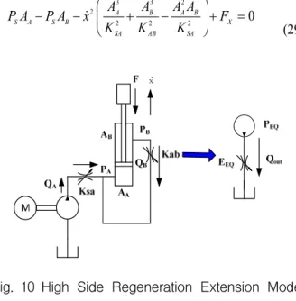
4.4 High Side Regeneration Extension Mode A similar derivation approach like the one for Power Extension mode can be done the High Side Regeneration Extension mode and a schematic diagram is shown in Fig. 10. To derive the mathematical model quasi-static assumptions are made again as previous.
The summation of forces acting on each side of the
cylinder is quasi-statically equal to a force denoted by F X can be calculated as,
X B B A A
F P A P A (28)
Now considering similar orifice equations applied in inlet an outlet orifice of power extension mode and then substituting into Eq. (28) the equation below is obtained,
3 3 2
2
2 2 2 0
A B A B
S A S B X
SA AB SA
A A A A
P A P A x F
K K K
(29)
X
Fig. 10 High Side Regeneration Extension Mode:
Mathematical Analysis and Equivalent System.
After rearranging, the bracketed part of the Eq. (29) equivalent valve conductance K EQ is found as following equation
2
(
3 2)
2SA AB EQ
SA AB
K K K
K R R K
(30)
Substituting Eqs. (8,28,30) into Eq. (29) then rearranging that equation leads,
; 0
B B EQ S A B S
Q xA K R P P P P x (31)
Eq. (31) is similar to the orifice equation so the part under the square root considered as equivalent pressure P EQ. That means:
EQ S A B S
P R P P P P (32)
So for controlling purpose Eqs. (31,32) are combined to get the subsequent equation
; 0
c B B
EQ c
EQ EQ
x A
K Q x
P P
(33)
where, x c is commandant velocity as previously described in the power extension mode. Recalling Eqs.
(16,30), calculation of each valve conductance can be described by,
3/2 3 2
SA EQ
K K R R R (34)
3/2 1/2
AB EQ 1
K K R R (35)
4.5 Low Side Regeneration Retraction Mode Using a similar type of schematic diagram and quasi-static assumptions simplified Low Side Regeneration Retraction mode can be modeled.
Considering inlet and outlet valve as a variable orifice can be written by the orifice equation as follows,
1 ; 0
B SA SA S B B
Q
K
P
K P
P
A x x
(36)
2 ; 0
A AB AB A B A
Q
K
P
K P
P
A x x
(37)
Eq. (38) and Eq. (39) are rearranged and substituted into the force summing equation then rearranged again for getting the following Eq. 38
3 3 2
2
2 A B 2 B 2 A 0
S A S B X
AB SA SA
A A A A
P A P A x F
K K K
(38)
For defining equivalent valve conductance similar calculation as previous mode is done and finally equivalent valve conductance K EQ is,
3 2 2
( )
SA AB EQ
SA AB