• 검색 결과가 없습니다.

Analysis on the Dosimetric Characteristics of Tangential Breast Intensity Modulated Radiotherapy

N/A
N/A
Protected

Academic year: 2021

Share "Analysis on the Dosimetric Characteristics of Tangential Breast Intensity Modulated Radiotherapy"

Copied!
10
0
0

로드 중.... (전체 텍스트 보기)

전체 글

(1)

Submitted August, 24, 2012, Accepted November, 5, 2012

Corresponding Author:Ju-Young Song, Department of Radiation Oncology, Chonnam National University Medical School, 8, Hak-dong, Dong-gu, Gwangju 510-840, Korea

Tel: 061)379-7224, Fax: 061)379-7249 E-mail: [email protected]

Analysis on the Dosimetric Characteristics of Tangential Breast Intensity Modulated Radiotherapy

Mee Sun Yoon, Yong-Hyeob Kim, Jae-Uk Jeong, Taek-Keun Nam, Sung-Ja Ahn, Wong-Ki Chung, Ju-Young Song

Department of Radiation Oncology, Chonnam National University Medical School, Gwangju, Korea The tangential breast intensity modulated radiotherapy (T-B IMRT) technique, which uses the same tangential fields as conventional 3-dimensional conformal radiotherapy (3D-CRT) plans with physical wedges, was analyzed in terms of the calculated dose distribution feature and dosimetric accuracy of beam delivery during treatment.

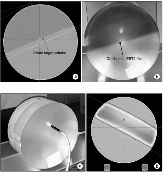
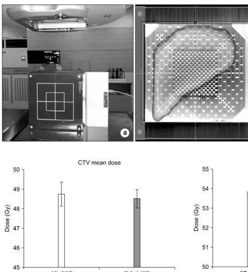
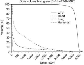
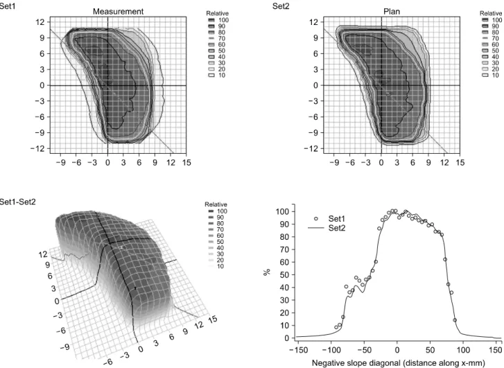
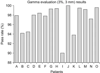
T-B IMRT plans were prepared for 15 patients with breast cancer who were already treated with conventional 3D-CRT. The homogeneity of the dose distribution to the target volume was improved, and the dose delivered to the normal tissues and critical organs was reduced compared with that in 3D-CRT plans. Quality assurance (QA) plans with the appropriate phantoms were used to analyze the dosimetric accuracy of T-B IMRT. An ionization chamber placed at the hole of an acrylic cylindrical phantom was used for the point dose measurement, and the mean error from the calculated dose was 0.7±1.4%. The accuracy of the dose distribution was verified with a 2D diode detector array, and the mean pass rate calculated from the gamma evaluation was 97.3±2.9%.

We confirmed the advantages of a T-B IMRT in the dose distribution and verified the dosimetric accuracy from the QA performance which should still be regarded as an important process even in the simple technique as T-B IMRT in order to maintain a good quality.

󰠏󰠏󰠏󰠏󰠏󰠏󰠏󰠏󰠏󰠏󰠏󰠏󰠏󰠏󰠏󰠏󰠏󰠏󰠏󰠏

Key Words: Tangential breast IMRT, Dose homogeneity index, Dose verification

INTRODUCTION

A 3-dimensional conformal radiotherapy (3D-CRT) plan us- ing 2 tangential fields is commonly applied for the treatment of breast cancer patients. The wedge technique is used to cor- rect the heterogeneous dose distribution in the target volume, which can be caused by difference in tissue thickness within the breast. The physical wedge technique increases the monitor units (MU), introducing more scatter dose to the normal tissue.

1,2)

Furthermore, the insertion of the wedge during the treatment process increases the treatment time and requires ex- tra care to prevent wedge slippage. Although virtual or dynam- ic wedge treatment using the Y-jaw movement during beam ir- radiation can provide a solution to this problem, the shielding

shape of the multi-leaf collimator (MLC) is not suitable owing to the potential for collimator rotation.

To overcome the problems associated with the wedge tech- niques, a simple intensity modulated radiotherapy (IMRT) me- thod that uses the same tangential fields as conventional 3D- CRT was developed and has been effectively applied in clin- ical treatment. The tangential breast IMRT (T-B IMRT) techni- que delivers intensity modulated beams that are calculated by inverse planning to achieve a homogeneous dose distribution in the target. Several studies have demonstrated the advantages of T-B IMRT in terms of the homogeneity of the dos dis- tribution in the target volume and the reduction of the dose delivered to the normal tissues and organ at risk (OAR) in comparison with conventional 3D-CRT using the wedge technique.

3-10)

The present study analyzed the suitability and effectiveness

of T-B IMRT by comparison with the calculated dose data for

3D-CRT using the wedge technique. In addition, the dose ac-

curacy of T-B IMRT was examined by measuring dose distri-

(2)

were measured using T-B IMRT quality assurance (QA) plans generated with the specialized phantoms and compared with calculated data to verify the dosimetric accuracy during the process of beam delivery.

MATERIALS AND METHODS

1. Plan comparison between 3D-CRT and T-B IMRT T-B IMRT plans were specifically generated for the 15 breast cancer patients who were treated with the breast con- serving surgery and already treated with conventional 3D-CRT using the wedge technique.

The 3D-CRT plans were created in the Eclipse system (Varian, PaloAlto, CA, USA) and the pencil beam convolution algorithm was used for dose calculation. The energy of photon was 6 MV and the applied fields were tangential fields with the insertion of physical wedge. The angle of the physical wedge was 30

o

or 45

o

, and only the lateral field was installed with the wedge, considering the less scattered dose to the con- tralateral breast.

The T-B IMRT plans were prepared with the direct aperture optimization algorithm

11-13)

in the Panther (Prowess, Concord, CA, USA) radiation treatment planning (RTP) system, and the dedicated linear accelerator (LINAC) for the plan was ARTISTE (Siemens, Erlangen, Germany). The CT and structure data for target and OARs were transferred using the DICOM RT for- mat, and the same gantry angles were maintained for the tan- gential fields. The prescription dose for the clinical target vol- ume (CTV) was 50 Gy applied in 25 fractions, and the beam intensity was modulated in each field by using 5 step and shoot subfields of different segment shapes. The CTV was de- lineated for the whole breast not including internal mammary nodes.

The optimization constraints for CTV were that 95% isodose (prescription) surface had to cover 95% of the CTV and no portion of the CTV could receive more than 110% of the pre-

lineated using a dummy structure in a normal tissue after the first dose calculation of T-B IMRT, and the dose constraint for the dummy structure was set at no more than 100% of the prescription dose.

The calculated dose data of T-B IMRT were compared with those of 3D-CRT, and each plan was normalized with the con- straint that 90% of the isodose surface should cover 90% of the CTV to enable the objective analysis of the dose data in the 2 plans. The mean dose, maximum dose and homogeneity index (HI)

14)

of the CTV were compared to analyze the appro- priateness and homogeneity of the dose distribution in the CTV. The mean dose of the lung and the hot-spot dose in normal tissue were analyzed to minimize the irradiated dose to the OARs and normal structures. The total MUs were also compared to evaluate the treatment time and effectiveness of the beam delivery.

HI = (D

2

-D

98

)

× 100% (1)

(D

prescription

)

D

2

: the dose to the 2% of the target volume, as displayed on the DVH

D

98

: the dose to the 98% of the volume as displayed on the cumulative DVH

D

prescription

: the prescription dose

2. Verification of dosimetric accuracy of T-B IMRT

The effectiveness of T-B IMRT with regard to the homoge-

neity of dose distribution in the target volume was analyzed

with the home-made cylindrical acrylic (density: 1.18 g/cm

3

)

phantom. Two cylindrical phantoms (20 cm in diameter and 5

cm thick) were combined, and the virtual breast target volume

was contoured on the CT images of the phantom as shown in

Fig. 1a. Conventional 2-tangential fields were set up, and 3

plans were generated, which differed in the application of the

beam intensity modulation device to the tangential fields: an

open field plan, one that used a physical wedge in the lateral

(3)

Fig. 1. Cylindrical acrylic phantom for the evaluation of the T-B IMRT function in the correction of hetero- geneous dose distribution. (a) vir- tual breast target volume contoured in the phantom. (b) EBT2 film inserted within the phantoms.

Fig. 2. Cylindrical acrylic phantom with the inserted ionization chamber for the absolute dose measure- ment in the QA process of T-B IMRT. (a) setup of the phantom system for the measurement of absolute dose at the calculated point.

(b) example of the created QA plan with the phantom in Panther RTP system.

field, and a T-B IMRT plan. The calculated dose distribution in each plan was compared with the dose measurement ob- tained using Gafchromic EBT2 film (International Specialty Products, Wayne, NJ, USA) inserted between the 2 cylindrical phantoms as shown in Fig. 1b. This was done to verify that a physical wedge and T-B IMRT could provide a solution to the heterogeneous dose distribution of the open-field plan. All the plans were created in the Panther system, and the ARTISTE LINAC was used for beam delivery.

The dosimetric accuracy of T-B IMRT was analyzed using QA plans that were created with the appropriate phantoms.

Two QA plans were created for each T-B IMRT patient to verify the absolute point dose and the dose distribution, result- ing in the generation and implementation of 30 QA plans for 15 patients for dose measurement.

For the measurement of point dose, a whole was drilled in

the cylindrical acrylic phantom for the insertion of the ioniza- tion chamber as shown in Fig. 2. The A1SL ion chamber (Standard Imaging, Middleton, WI, USA) was used, and the CT images were acquired and applied for the creation of QA plans with the Panther RTP system. An A1SL ion chamber with 0.057 cm

3

of air volume and a DOSE1 (IBA Dosimetry, Schwarzenbruck, Germany) electrometer were used for the measurement of point dose. The relative calibration process for the measurement of a point dose was performed in the con- ditions of 10×10 cm

2

field size, 100 cm SAD (source to axis distance) and 5 cm depth. The location of measured point was designated to the target center area which showed homoge- neous dose distribution.

The accuracy of dose distribution was analyzed with

MapCHECK (SunNuclear, Melbourne, FL, USA), a 2D diode

detector array that was inserted into the MapPHAN (SunNu-

(4)

MapCHECK, with MapPHAN phan- tom for the evaluation of dose dis- tribution in the QA process of T-B IMRT. (a) placement of MapCHECK system for the measurement of sagittal dose distribution. (b) ex- ample of the calculated dose dis- tribution in the plane of the de- tector array.

Fig. 4. Comparison of the average value of CTV mean dose between 3D-CRT and T-B IMRT.

Fig. 5. Comparison of the average value of CTV maximum dose between 3D-CRT and T-B IMRT.

clear, Melbourne, FL, USA), a water equivalent solid phantom, and the CT images were acquired with the placement of diode array's plane in the sagittal direction. The QA plans were cre- ated in the Panther RTP system, and the measurements of the beam delivery were performed in the same phantom position as that used for CT image acquisition, which is shown in Fig.

3. The coincidences in dose distribution were analyzed with the gamma evaluation method, and the selected tolerance pa- rameters for the gamma index were 3% dose difference and 3 mm distance to agreement between the calculated dose and the dose measured with the MapCHECK.

RESULTS

The comparisons of the plan output between 3D-CRT using a lateral physical wedge and T-B IMRT are shown in Fig. 4 to 9. Fig. 10 shows an example of dose volume histogram cal- culated from T-B-IMRT plan.

The average CTV mean doses for each plan are shown in

Fig. 4, which demonstrates that adequate mean doses were

produced by the 2 plans that were similar to the prescribed

dose of 50 Gy. However, the 3D-CRT plan produced a dose

of 48.7 Gy, which is slightly higher than the 48.5 Gy pro-

duced by T-B IMRT. Fig. 5 shows the results of the compar-

ison of maximum doses in the CTV, and shows that the

(5)

Fig. 6. Comparison of the average homogeneity index (HI) in CTV between 3D-CRT and T-B IMRT.

Fig. 7. Comparison of the average value of lung mean dose between 3D-CRT and T-B IMRT.

Fig. 8. Comparison of the average value of the hot-spot dose in a normal tissue between 3D-CRT and T-B IMRT.

Fig. 9. Comparison of the average calculated monitor unit between 3D-CRT and T-B IMRT.

3D-CRT plan produced a higher average maximum dose (53.8 Gy) than the T-B IMRT plan (52.9 Gy). The HI of the CTV was higher for 3D-CRT, with an average value of 0.35 com- pared with 0.28 in T-B IMRT, as shown in Fig. 6. A lower HI value indicates a more homogeneous dose distribution;

therefore, the present results demonstrate that the homogeneity of dose distribution in the CTV was higher in the T-B IMRT plans than in the 3D-CRT plans.

The average values of the lung mean dose was 3.8 Gy for 3D-CRT plans and 3.2 Gy for T-B IMRT, as shown in Fig. 7.

Fig. 8 shows that the average hot-spot dose in normal tissue in the 3D-CRT plans (54.5 Gy) was higher than that in T-B IMRT plans (53.6 Gy). These results demonstrates that T-B IMRT plans were superior to 3D-CRT plans in terms of re-

ducing the dose to the normal tissues and OARs.

The average of irradiated MUs for each treatment was 320.5 for 3D-CRT and 257.9 for T-B IMRT, as shown in Fig. 9, which indicates that T-B IMRT was more effective with re- gard to the time and work requirements during the treatment.

The effect of T-B IMRT on the correction of the heteroge-

neous dose distribution and the role of a physical wedge in

3D-CRT were shown in Fig. 11. The dose distributions ob-

tained by the irradiating films inserted between the cylindrical

phantoms suggest that higher doses were delivered to the ante-

rior part of the phantom, which is characterized by reduced

thickness in the direction of the beam angle when only open

fields were applied. The problem of inhomogeneous dose dis-

tributions could be solved by applying the physical wedge and

(6)

Fig. 10. Example of the dose volume histogram (DVH) calculated from T-B-IMRT plan.

Fig. 11. Film analysis results for the verification of the T-B IMRT function to make correction of the inhomogeneous dose distribution.

(a) dose distribution applying the open fields. (b) dose distribution applying the physical wedge. (c) dose distribution applying the T-B IMRT.

QA plans for T-B IMRT was 0.7±1.4%, confirming the accu- racy of the dose calculation with respect to the delivered dose in T-B IMRT.

Fig. 13 shows an example of the dose distribution analysis

that was performed with the MapCHECK, 2D diode detector

array. The mean pass rate in the gamma evaluation between

the measured dose distribution and the dose calculated with

the 15 QA plans for T-B IMRT was 97.3±2.9%, as shown in

Fig. 14, which confirmed the accuracy of the T-B IMRT dose

distributions.

(7)

Fig. 12. Absolute dose difference between the calculated doses in the QA plans for T-B IMRT and the measurement ones.

Fig. 13. Example of the dose distribution analysis which shows the difference between the calculated data in the plan and the measured data with the MapCHECK.

DISCUSSION

The results of our analyses showed that T-B IMRT can de- liver a more homogeneous dose to the target volume and min- imize the dose to normal tissues and OARs around the target compared with 3D-CRT using a physical wedge, thus confirm- ing the results of previous studies on T-B IMRT.

Although the use of only 2 tangential fields in T-B IMRT

results in a limited capacity to fit the prescribed isodose sur-

face to the target shape, unlike conventional IMRT, which

uses more than 5 fields, the removal of fields in the direction

of the lung enables the reduction of the irradiated dose to this

important OAR. However, the limited beam angle of the tan-

gential fields can result in the generation of a hot-spot in the

(8)

Fig. 14. Pass rate calculated in the gamma evaluation for the comparison of the calculated dose distributions in the QA plans for T-B IMRT with the measured data by the MapCHECK.

normal tissue in the posterior axillary region. A constraint re- garding the removal of the hot-spot was applied in the opti- mization process in the present study, and the high dose could be reduced to relatively lower values. This was the only con- straint for OARs in this study. Although additional constraints for other OARs, such as the lung, heart, and humerus, can be applied to the optimization process, this may make it difficult to reach the appropriate dose owing to the limited number of fields in T-B IMRT. Therefore, the number of OARs in the optimization process should be kept low considering the diffi- culty in achieving the dose requirement and the simple plan- ning process because T-B IMRT was already shown to pro- duce a low dose in OARs without the specified constraints in the optimization.

Although T-B-IMRT produced the better dose distribution in the analysis of DVH, the results were not considered statisti- cally significant. However, T-B-IMRT was proved as a effec- tive treatment method which can replace the conventional 3D-CRT and even more it showed the certain advantages in the process of treatment in the aspect of removing the time consuming wedge insertion and decrease of total monitor unit.

The QA for conventional IMRT should be performed before the treatment to verify the accuracy of the delivered dose com- pared with the calculated data in the RTP system. QA studies are not commonly performed for T-B IMRT because the meth- od is based on relatively simple beam modulation using a lim-

cylindrical acrylic phantom, which enabled the simulation of the geometry of the breast. In the second process, the dose distribution was analyzed using the 2D diode detector array, MapCHECK.

The measured point doses and the dose distribution data for the 15 T-B IMRT patients obtained using the QA showed good agreement with the calculated data in the RTP system, which verified the accuracy of the Panther RTP and ARTISTE LINAC systems for T-B IMRT delivery.

Although the dose distribution is usually assessed using film measurements, 2D diode detector array was used to minimize expenses and because the MapCHECK is an effective method for the analysis of the pass rate values from the gamma evalu- ation process. The MapCHECK was placed in the sagittal di- rection of detector arrays in this study because it enabled the analysis of the wider dose distributions caused by the tangen- tial fields of T-B IMRT.

Although the results of the present study confirmed the ac- curacy of T-B IMRT using QA plans, there was a variation in the accuracy of dose distribution between the patients. This in- dicates that QA should be performed before the administration of T-B IMRT in every patient. If performing QA for all the patients is not feasible, it should be done periodically with a randomly selected plan, to maintain the quality of the T-B IMRT systems.

T-B IMRT can be more sensitive to setup error because of the difficulty in the geometrical repeatibility due to the soft tissue feature of breast. It can be also influenced with the breast motion owing to respiration than conventional 3D-CRT in terms of dosimetric variation.

15-17)

Image guided radiation therapy (IGRT) should therefore be performed before beam de- livery to correct the setup error, and an appropriate method for reducing the effects of respiratory organ motion, such as respi- ratory gated radiation therapy,

18,19)

should be considered to en- sure the accuracy of T-B IMRT.

The respiratory target motional effect can introduce some er-

(9)

ror in the real breast treatment, which should be considered in the future study with the analysis of dosimetric errors in T-B-IMRT compared with the conventional 3D-CRT under the respiratory motional conditions.

CONCLUSIONS

The present study confirmed that T-B IMRT could produce equal or better results with regard to a homogeneous dose dis- tribution in the target volume and reduction of the dose to the OARs compared with conventional 3D-CRT with a physical wedge. Although the results were not considered statistically significant, T-B-IMRT was proved as an effective treatment method which can replace the conventional 3D-CRT in the as- pect of removing the time consuming wedge insertion and de- crease of total monitor unit. The agreement between the calcu- lated data from RTP and the measurement data from T-B IMRT was confirmed using QA plans, which are important to maintain the quality of T-B IMRT treatment.

REFERENCES

1. Woo TC, Pignol JP, Rakovitch E, et al: Body radiation ex- posure in breast cancer radiotherapy: impact of breast IMRT and virtual wedge compensation technique. Int J Radiat Oncol Biol Phys 65:52-58 (2006)

2. Borghero YO, Salehpour M, McNeese MD, et al: Multileaf field-in-field forward-planned intensity-modulated dose com- pensation for whole-breast irradiation is associated with reduced contralateral breast dose: a phantom model comparison.

Radiother Oncol 82:324-328 (2007)

3. Hong L, Hunt M, Chui C, et al: Intensity-modulated tangen- tial beam irradiation of the intact breast. Int J Radiat Oncol Biol Phys 44:1155-1164 (1999)

4. Van Asselen B, Raaijmakers CP, Hofman P, et al: An improved breast irradiation technique using three-dimensional geometrical information and intensity modulation. Radiother Oncol 58:341-347 (2001)

5. Chui CS, Hong L, Hunt M, et al: A simplified intensity modulated radiation therapy technique for the breast. Med Phys 29:522-529 (2002)

6. Bhatnagar AK, Brandner E, Sonnik D, et al: Intensity modulated radiation therapy (IMRT) reduces the dose to the contralateral breast when compared to conventional tangential

fields for primary breast irradiation. Breast Cancer Res Treat 96:41-46 (2006)

7. Selvaraj RN, Beriwal S, Pourarian RJ, et al: Clinical im- plementation of tangential field intensity modulated radiation therapy (IMRT) using sliding window technique and dosimetric comparison with 3D conformal therapy (3DCRT) in breast cancer. Med Dosim 32:299-304 (2007)

8. Herrick JS, Neill CJ, Rosser PF: A comprehensive clinical 3-dimensional dosimetric analysis of forward planned IMRT and conventional wedge planned techniques for intact breast radiotherapy. Med Dosim 33:62-70 (2008)

9. Jagsi R, Moran J, Marsh R, et al: Evaluation of four techni- ques using intensity-modulated radiation therapy for compre- hensive locoregional irradiation of breast cancer. Int J Radiat Oncol Biol Phys 78:1594-1603 (2010)

10. Schubert LK, Gondi V, Sengbusch E, et al: Dosimetric comparison of left-sided whole breast irradiation with 3DCRT, forward-planned IMRT, inverse-planned IMRT, helical tomother- apy, and topotherapy. Radiother Oncol 100:241-246 (2011) 11. Shepard DM, Earl MA, Li XA, et al: Direct aperture opti-

mization: a turnkey solution for step-and-shoot IMRT. Med Phys 29:1007-1018 (2002)

12. Zhang G, Jiang Z, Shepard D, et al: Direct aperture opti- mization of breast IMRT and the dosimetric impact of respiration motion. Phys Med Biol 51:N357-369 (2006)

13. Ahunbay EE, Chen GP, Thatcher S, et al: Direct aperture optimization-based intensity-modulated radiotherapy for whole breast irradiation. Int J Radiat Oncol Biol Phys 67:1248-1258 (2007)

14. Wu Q, Mohan R, Morris M, et al: Simultaneous integrated boost intensity modulated radiotherapy for locally advanced head- and-neck squamous cell carcinomas. I: dosimetric results. Int J Radiat Oncol Biol Phys 56:573-585 (2003)

15. Cao J, Roeske JC, Chmura SJ, et al: Calculation and pre- diction of the effect of respiratory motion on whole breast radia- tion therapy dose distributions. Med Dosim 34:126-132 (2009) 16. Leonard CE, Tallhamer M, Johnson T, et al: Clinical ex-

perience with image-guided radiotherapy in an accelerated par- tial breast intensity-modulated radiotherapy protocol. Int J Radiat Oncol Biol Phys 76:528-534 (2010)

17. Sijtsema NM, Van Dijk-Peters FB, Langendijk JA, et al: Electronic portal images (EPIs) based position verification for the breast simultaneous integrated boost (SIB) technique.

Radiother Oncol 102:108-114 (2012)

18. Korreman SS, Pedersen AN, Nøttrup TJ, et al: Breathing adapted radiotherapy for breast cancer: comparison of free breathing gating with the breath-hold technique. Radiother Oncol 76:311-318 (2005)

19. Korreman SS, Juhler-Nøttrup T, Persson GF, et al: The

role of image guidance in respiratory gated radiotherapy. Acta

Oncol 47:1390-1396 (2008)

(10)

기존의 쐐기(wedge) 필터를 사용하는 접선조사(tangential irradiation) 방식의 일반적인 유방암 방사선치료와 동일한 접선 조사야(filed)를 사용하면서 쐐기 필터를 삽입하는 대신 다엽콜리메터의 움직임을 통해 치료부위의 선량분포를 균일하게 형성토록 하는 접선 세기조절 방사선치료(tangential breast Intensity modulated radiotherapy, T-B IMRT)가 유방암치료에 적용되고 있다. 본 연구에서는 T-B IMRT치료계획에서 계산된 선량분포를 기존의 쐐기 필터를 사용한 일반적인 접선조 사 방식의 치료계획과 비교하여 치료표적 및 중요장기에서의 선량분포 측면에서 T-B IMRT의 타당성을 살펴보고, 실제 T-B IMRT치료 빔 조사 시 선량 측정 및 치료계획 결과와의 오차 분석을 통해 선량 분포의 정확도를 확인하고자 하였다.

기존의 쐐기필터를 이용한 접선조사 방식으로 치료한 유방암 환자 15명을 대상으로 T-B IMRT치료계획을 세운 후, 계산 된 선량분포를 비교, 분석하였다. T-B IMRT치료계획에서 치료표적 부피 내 선량분포의 균일도가 기존의 쐐기를 사용한 접선조사 방식보다 향상된 결과를 보였으며, 주변의 정상조직과 중요장기의 선량을 상대적으로 줄일 수 있음을 확인할 수 있었다. T-B IMRT의 실제 치료조사 시 선량정확도를 분석하기 위해 적합한 팬텀을 사용하여 품질보증(QA) 치료계획 을 수립하였다. 원기둥 형태의 아크릴에 이온전리함을 삽입한 형태의 팬텀을 사용하여 치료계획과 실제 치료 빔 조사를 통해 측정된 절대선량 값을 비교하였으며, 평균 오차는 0.7±1.4%로 분석되었다. 이차원 다이오드 검출기 배열장치를 이 용한 선량분포의 정확도 분석에서는 치료계획 시 계산된 선량분포와 실제 측정된 선량분포의 gamma evaluation (3%, 3 mm 기준)를 통해 평균 97.3±2.9%의 합격률(pass rate)로 타당성 있는 정확도를 보여주었다. 본 연구를 통해 선량분포 측 면에서 기존 쐐기필터를 이용한 접선 조사방식의 방사선치료 대비 T-B IMRT의 장점을 확인할 수 있었고, T-B IMRT에 적합하게 수립된 품질보증 과정을 통해 실제 조사되는 선량의 정확도를 확인할 수 있었다.

중심단어: 접선 세기조절 방사선치료, 선량 균일 지수, 선량 확인

수치

Fig.  1.  Cylindrical  acrylic  phantom  for  the  evaluation  of  the  T-B  IMRT  function  in  the  correction  of   hetero-geneous  dose  distribution
Fig.  4.  Comparison  of  the  average  value  of  CTV  mean  dose  between  3D-CRT  and  T-B  IMRT.
Fig.  9.  Comparison  of  the  average  calculated  monitor  unit  between  3D-CRT  and  T-B  IMRT.
Fig.  10.  Example  of  the  dose  volume  histogram  (DVH)  calculated  from  T-B-IMRT  plan.
+3

참조

관련 문서

The present study evaluated the feasibility, early toxicity, initial efficacy, and cosmetic outcomes of accelerated partial breast intensity-modulated radiotherapy (IMRT) for

we performed 3D conformal radiation therapy (3D-CRT), intensity-modulated radiation therapy (IMRT), and tomotherapy on 10 patients with brain tumors in the frontal

Department of Radiation Oncology, Chonnam National University Medical School, Gwangju, Korea The applicability and feasibility of TomoTherapy in the lung

The aim of this study was to compare the dose distribution of intensity modulated radiation therapy (IMRT) with 3 dimensional conformal radiation therapy (3DCRT) in

IMRT, intensity-modulated radiotherapy; PTV, planning target volume body-PTV, whole body without PTV; p-value (x vs. y), p-value be- tween x-MV and y-MV IMRT technique. a)

IMRT: intensity-modulated radiation therapy; LAD: left anterior descending artery; LN: lymph node; OAR: organ at risk; PTV: planning target volume; RNI: regional node irradiation;

결론적으로 SCL을 포함한 유방암 방사선 치료 시 조사 야에 인접한 MLC가 접합부 선량에 미치는 영향을 확인한 결과, 접합부에 MLC가 모두 적용된 계획과 모두 Retract 한 계획

Purpose: To analyze differences in the dose uniformity for the computed breast radiation therapy planning with tangential beam between conventional RT