Correlation Analysis of Transmission and Reflection Angle of Propagation Characteristics from 13-28 GHz
Yong Won Kim*, Won Ho Jeong*, Sang Lim Ju*, and Kyung Seok Kim**
ABSTRACT
In order to derive reliable propagation models for future millimeter-wave frequency indoor pico-cellular communications systems, accurate reflectivity data of building materials is necessary. The broad variety of building materials and construction codes makes accurate attenuation prediction very difficult without the support of specific construction data or measurements.
This paper derives a transmission and reflection coefficient based on 13 GHz to 28 GHz measurement data. Transmission and reflection is measured by applying change in the reception angle of each building material, such as plasterboard. The transmission and reflection coefficient derived shows a correlation between frequency dependence and angle. As a result, as the reception angle is reduced, the reflected angle from the transmitter that could be received increases, showing that there is a correlation. In addition, the fundamental investigations carried out lay the foundation for radio channel–related research, which is essential for the development of future millimeter-wave communications systems.
Key Words : Transmission, Reflection, Correlation coefficients, Mobile communication
*Chungbuk National University, Department of Radio and Communication Engineering
**Corresponding Author, Chungbuk National University, Department of Information and Communication Engineering ([email protected]) 접수일자 : 2016년 06월 28일, 최종게재확정일자 : 2016년 06월 29일
I. Introduction
Data rates in wireless communications systems are growing steadily. Upcoming wireless personal area network standards like IEEE 802.15.3c or ECMA-387 will use the unlicensed 20 GHz band, targeting data rates of up to 6 Gbps per channel. Regarding even higher carrier frequencies, wireless transmission was demonstrated at 120 GHz, where data rates of 10 Gbps could be achieved.
This frequency range is of special interest since it contains the industrial, scientific and medical bands [1].
Material reflectivity has been studied thoroughly in the microwave and lower millimeter-wave region. For example, aspects like scattering from rough surfaces or the effect of multiple reflections have been investigated for frequencies beyond 100 GHz. However, this frequency range has still not been fully explored in terms of propagation phenomena [2]. On the one hand, there is a lack of measurement and simulation data for transmission properties when building optically thin and layered media, and only a few materials have been investigated so far.
Modeling of wave propagation through building walls has a significant impact on the planning of urban cellular telephone systems. The construction of walls is usually
based on architectural and structural considerations, and even if the types of elements used are known, their influence on electromagnetic waves is difficult to predict.
Rigorous analytical and numerical methods have been applied to studying models of nonhomogeneous building walls, but most of them have not been compared with measured data. Unused or underutilized local multipoint distribution system broadband spectrum exists at 28 GHz, and given the low atmospheric absorption compared to 60 GHz, the spectrum at 28 GHz has free-space path loss comparable to today’s 1 GHz to 2 GHz cellular bands [2].
In addition, despite myths to the contrary, rain attenuation and oxygen loss does not significantly increase at 28 GHz, and, in fact, may offer better propagation conditions, compared to today’s cellular networks, when one considers the availability of high gain adaptive antennas and cell sizes on the order of 200 meters [3].The design and optimization of future millimeter-wave mobile communications systems is highly influenced by the spatial multipath characteristics of the wireless channel. A fundamental relationship was established between the angular distribution of power in a multipath channel and narrowband fading in a local region.
Ⅱ. System Model and Methods
1. Transmission
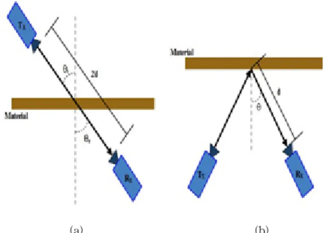
The transmitter (TX) and receiver (RX) were moved to each side of a test material while still maintaining a separation distance of 0.6 m. Both TX and RX were placed 0.3 m away from the test material with identical antenna heights of 1.2 m, as seen in Fig. 1. In all tests, vertically polarized 13-28 GHz radio waves were transmitted with directional antennas pointing at each other, normal to the test material. Measurements of penetration loss for common building materials (e.g., particleboard) were conducted at all three locations. The antenna alignment of transmission geometry is shown schematically in Fig. 2.
The measurements were conducted for vertical linear polarization of the antennas and are shown in our system link budget.
(a) (b)
Fig. 1. Measurement setup (a) transmission (b) reflection
Fig. 2. System link budget
2. Reflection
To measure the reflected power from a test material, the TX and RX were separated by a distance of 0.6 m from the material with the antennas oriented at different
incident angles (θ = 15˚, 30˚, 45˚ and 60˚) to particleboard.
Reflective surfaces at 13-28 GHz allow radio frequency (RF) energy to be contained within the building, which reduces co-channel intercellular interference that could leak outside of the building, and thus suggests high frequency reuse between indoor and outdoor communications. This also illuminates difficulties in achieving indoor coverage with outdoor infrastructure, as the buildings appear very difficult to penetrate from the outside at 13-28 GHz. Relays and ultra-wideband repeaters will likely be required to achieve indoor-to-outdoor coverage, or else outdoor mobile users will need to hand off to indoor communications system as users enter a building.
Material
(received angle) L0 n Xσ
LOS(10°) -34.66 -0.1843 0.0601
LOS(20°) -38.71 -0.5052 0.1579
LOS(30°) -47.65 -0.1451 0.0465
Particleboard (10°) -38.31 -0.9822 0.3122 Particleboard (20°) -41.71 -1.491 0.4769 Particleboard (30°) -50.70 -0.9635 0.3071 Table 1. Received Power Constant
Ⅲ. Impact of Transmission and Reflection from Angle of
Propagation
1. Measurement Data
The distance-dependent part of the path loss is modelled to be a function of frequency, f, as
(1)
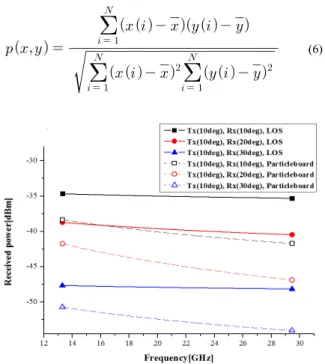
where L0 is the initial value at the reference frequency, f0, at 13.5 GHz, n is the path loss index, and Xσ is the standard deviation. The received power results are shown in Table I and in Fig. 3, along with the fitting results. We can see the transmission loss of particleboard by about 4 dB of generation compared to line-of-sight power as a reference, where 10 degrees increases the reception angle, and a loss of about 5 dB occurs. Because transmit and receive antennas are directional antennas, it is a loss that occurs when placing the two antennas, which means that it is necessary to arrange them opposite to one another.
We calculate the reflection coefficients R and
transmission coefficients T from our measurement data using Fresnel’s equations [5].
′
(2)
′
′ (3)
The transitivity is limited to smooth materials only.
′
′
(4)
(5)
2. Correlation Analysis of Transmission and Reflection coefficients
The correlation of the transmission and reflection observed in the measured data is reflected in joint probability distributions. [6]:
(6)
Fig. 3. Received power according to frequency (transmission)
Generally, as reception angle increases, the transmission coefficient will appear in a form that is reduced. Fig. 4 (a) results showed a reduced tendency of the derived transmission coefficient, so theoretically the deviation shown is small.
We derived the transmission coefficient from the results of measurements, which showed that it falls with a larger deviation. The millimeter-wave measurement effect indicates
that it is different from the theoretical equation. This indicates that the measured values and theoretical values are different; the reason being propagation characteristics and the measurement system. Using theory of the dielectric constant, the receiving angle formula is calculated taking into account the medium’s thickness, but not the environment, because it does not reflect the actual measurement. It does not always have a negative value correlation in a pico cell environment. The attenuation of power is different for the surrounding environment compared to the Fresnel equation, which reflects millimeter-wave propagation characteristics of real environments.
(a)
(b)
Fig. 4. Comparison of theoretical and experimental data (a) transmission (b) reflection
Reflection is shown graphically in Fig. 4 (b), which shows how the reflection coefficient changes with increases in the angle. The reflection coefficient was shown to increase as the reception angle increases. The reason is that as the reception angle increases, the transmission loss decreases. The value derived by the measurement, shown with a solid line, compared to the theoretical value, indicated with a dotted line, shows a pattern that is less constant. With the exception of the 28 GHz band, the difference between the two values shown
is within 0.2. The theoretical results are slightly different from the measurement results, but their tendencies are similar, with a difference within 0.2, which is quite slight when considering the overall tendency towards a decrease.
However, in the 28 GHz band, we can see that the reflection characteristics are not good compared to the other bands. It means that instead of the 28 GHz band, known from the measured data, radio propagation has better reflection in the 13 GHz band through plasterboard.
Reflection is the measure of how the multipath components arrive relative to the mean angle of arrival.
Transmission is commonly measured in degrees and describes the width of the sector from which most of the received signal power arrives. Reflection has a negative correlation when the receiver is away from the transmitter because the former receives a relatively small angle of the signal. But the value of the cross-correlation coefficient is reduced when building density increases. This is due to buildings and vehicles causing reflection or diffraction.
Thus, the receiver receives at a large incidence angle from the transmitter.
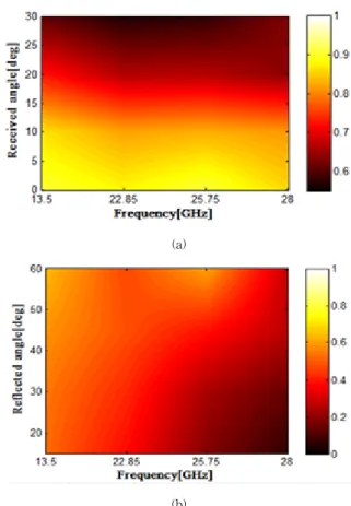
Fig. 5 is a joint distribution with the results derived by measurement and shown by reflected angle and received angle. First, transmission shows that the transmission coefficient is high, and is shown with the lighter color.
The low frequencies show a higher transmission coefficient than any other frequency. This shows the propagation characteristics of transmission in the 13-28GHz band. In addition, the transmission coefficient is such that higher reception angles are reduced. This indicates that the transmission loss occurs as reception angle is increased. In order to verify our proposed model, we configured a real propagation environment. The millimeter-wave measurement effect indicates that it is different from the theoretical equation. This indicates that the measured values and theoretical values are different, the reason being propagation characteristics and the measurement system. Using theory of the dielectric constant, the receiving angle formula is calculated taking into account the medium thickness, but not the environment, because it does not reflect the actual measurement. Therefore, the proposed model in this paper is reliable. In the 28 GHz band we can see that the reflection characteristics are not good compared to the other bands, which means that instead of the 28GHz band, known from the measured data, radio propagation has better reflection in the 13 GHz band through plasterboard.
(a)
(b)
Fig. 5. Joint distribution between frequency and angle of propagation (a) transmission (b) reflection
Ⅳ. Conclusion
This paper focused on deriving reliable propagation models for future millimeter-wave frequency indoor pico-cellular communications systems, because accurate reflectivity data of building materials is necessary. The broad variety of building materials and construction codes makes accurate attenuation prediction very difficult without the support of specific construction data or measurements.
This paper derived a transmission and reflection coefficient based on 13-28GHz measurement data. Transmission and reflection were measured by applying change in the reception angle of each building material, such as plasterboard. The transmission and reflection coefficient derived showed a correlation between frequency dependence and angle. As a result, as the reception angle is reduced, the reflected angle from the transmitter that could be received increases, showing that there is a correlation. In addition, the fundamental investigations carried out lay the foundation for radio channel related research, which is essential for the development of future millimeter-wave communications systems.
References
[1] Recommendation ITU-R P.1407-4, “Multipath propagation and parameterization of its characteristics,” 2009.
[2] O. Landron et al., “A Comparison of Theoretical and Empirical Reflection Coefficients for Typical Exterior Wall Surfaces in a Mobile Radio Environment”, IEEE Trans. Antennas and Propagation, vol. 44, no.3, Mar. 1996, pp. 341-351.
[3] C. Jansen et al., “The Impact of Reflections From Stratified Building Materials on the Wave Propagation in Future Indoor Terahertz Communication Systems”, IEEE Trans.
Antennas and Propagation, vol. 56, no.5, May. 2008, pp.
1413-1419.
[4] D. Pena et al., “Measurement and Modeling of Propagation Losses in Brick and Concrete Walls for the 900-MHz Band”, IEEE Trans. Antennas and Propagation, vol. 51, no.1, Jan.
2003, pp. 31-39.
[5] I. Cuinas et al., “Measuring, Modeling, and Characterizing of Indoor Radio Channel at 5.8 GHz”, IEEE Trans. Vehicular Technology, vol. 50, no.2, Mar. 2001, pp.526-535.
[6] J. Ahmadi-Shokouh et al., “Reflection Coefficient Measurement for North American House Flooring at 57–64 GHz”, IEEE Trans. Antennas and Propagation Letters, vol.
10, 2011, pp. 1321-1324.
[7] K. Sato et al., “Measurements of Reflection and Transmission Characteristics of Interior Structures of Office Building in the 60-GHz Band”, IEEE Trans. Antennas and Propagation, vol. 45, no.12, Dec. 1997, pp. 1783-1791.
[8] P. Poesiewicz et al., “Scattering Analysis for the Modeling of THz Communication Systems”, IEEE Trans. Antennas and Propagation, vol. 55, no.11, Nov. 2007, pp. 3002-3009.
[9] S. Priebe et al., “Channel and Propagation Measurements at 300 GHz”, IEEE Trans. Antennas and Propagation, vol. 59, no.5, May. 2011, pp. 1688-1698.
[10] H. Zhao et al., “28 GHz Millimeter Wave Cellular Communication Measurements for Reflection and Penetration Loss in and around Buildings in New York City”, IEEE ICC Wireless Communications Symposium,.
2013, pp. 5163-5167.
Author
Yong Won Kim
․received the MS degree in radio communication engineering from Inha University, Korea, in 2001 and 2003.
He is currently working towards the PhD degree with the school of wireless communication engineering of Chungbuk National University. His research interests VLC and digital radio
Won Ho Jeong
․received the BS degree in information and communication engineering and the MS degree in wireless communication engineering from Chungbuk National University, Korea, in 2011 and 2013. He is currently working towards the PhD degree with the school of wireless communication engineering of Chungbuk National University. His research interests include MIMO wireless channel, DDC and digital radio.
Sang Lim Ju
․received the BS degree in information and communication engineering and the MS degree in radio and communication engineering from Chungbuk National University, Korea, in 2014 and 2016. He is currently working towards the PhD degree with the school of radio and communication engineering of Chungbuk National University. His research interests include MIMO wireless channel, PLC and digital radio.
Kyung Seok Kim
․received the PhD degree in electrical and electronics engineering from Surrey University, the United Kingdom, in 2002. He worked for ETRI from 1989 to 1998 and from 2002 to 2004. He is currently working as a professor in Chungbuk National University, Korea.
His research interests include SDR, cognitive radio, power line communication, satellite security. digital radio and MIMO wireless channel. He is a member of the computer information communication research center.