*교신저자: 이이규규복복
700-721 대구광역시 중구 삼덕2가 188-1번지 경북대학교 치과병원 6층 치과보철과 053-600-7651: e-mail, [email protected] 원고접수일: 2009년 6월 19일 / 원고최종수정일: 2009년 9월 10일 / 원고채택일: 2009년 9월 15일
서론
치과용 임플란트의 경부를 둘러싸고 있는 조직은 대단 히 가혹한 조건에 노출된다. 이 부위의 연조직과 경조직 은 임플란트 식립시 피판 거상 등 수술에 따른 조직손 상,1,2
drilling에 의한 열손상
3등을 받을 수 있고, 구강환경 의 생화학적 자극과 저작압에 따른 응력을 지탱하여야 한다. 외부자극이 생리적 허용치를 넘는 경우 조직의 퇴 축이 생길 수 있고, 임플란트 지지골, 특히 경부골의 퇴축 이 관리되지 않으면 장기적으로 임플란트의 실패로 이 어질 수 있으므로 유의를 요한다.4임플란트 경부골의 퇴축 원인에 대해서는 아직 학문적 논란이 진행되고 있다. 주요 인자로 거론되어온 것들에 는 외과시술에 의한 손상,1과하중,5임플란트 주위염,6고 정체/지대주 연결부의 미세한 틈새,6-8생물학적 폭경,9-11 임플란트 경부의 디자인,12등이 포함된다. 구강조건에서 는 여러 인자들이 중첩하여 작용하므로 각 인자들간의 상호관계를 정량적으로 규명하기 위해서는 아직 많은 노력이 필요할 것이다. 그러나, 유한요소법에 의한 다수 선학들의 생역학적 연구에 따르면 임플란트 경부골에는 높은 응력집중이 일어나며, 이는 임플란트의 모델이나
사이즈 및 디자인 차이13,14에 무관하게, 또 골질 등 골조건
15-18이나 임플란트에 작용하는 하중 방향19-21에 무관하게
항상 생기는 것으로 보고되었다. 응력이 골 재형성에 영 향을 미치는 것은 1800년대에 Wolff에 의해 거론된 이래 정형학 분야에서 일반적 지식으로 받아들여지고 있으며22 치과영역에서도 교정적 치아이동의 기본적인 기구23로 이해되고 있다. 따라서 경부골의 과도한 응력집중이 골 흡수의 주요 원인 중 하나로 지목되는 것은 타당해 보이
며,5,24-26한편 동물실험27,28이나 임상적 관찰29등을 통해 그
타당성이 입증되고 있다.
경부골의 흡수가 반드시 경부골의 응력집중을 악화시 키거나 나아가 임플란트 실패로 이어지는 것은 아니지
만,20,30,31임플란트 주위골에 생기는 접시형 (saucer shape)
골소실은 임플란트 주위염의 가능성을 크게 할 수 있으 며32또한 치관 대 치근 비율의 악화로 인해 굽힘모멘트가 증가되어 나사풀림이나 임플란트의 기계적 파절을 일으 킬 수 있다.20,31이러한 배경하에 경부골 응력 감소를 위한 연구가 진행되어 왔다. 임플란트 식립 개수를 늘려서 임 플란트당 작용하는 힘을 경감시키거나, 길이나 직경이 큰 임플란트 사용을 통해 응력완화를 시도하였고,17,33임 플란트 나사의 디자인,13,34지대주 디자인,13,25임플란트 표 실행하였다.
결과: 최대 골응력은 치은관통부가 직선인 기본모델에서 가장 컸으며, 치은 관통부를 곡선으로 설계한 경우 응력이 감소되었다. 치은 함몰부가 클수록 응력 감소 정도가 커졌으며 함몰부의 수직위치가 몸체부에 가장 가까운 Model-4에서 응력감소 정도가 전체의 약 5%로 가장 컸다.
결론: 임플란트의 경부 형상은 골응력에 영향을 미치며, 이를 곡선형으로 함으로써 또한 그 함몰부를 몸체부에 근접하게 함으로써 경부골 응력감소를 효과 적으로 도모할 수 있다. (대한치과보철학회지 2009;47:394-405)
주요단어: 일체형 임플란트, 경부 형상, 유한요소법, 경부골 응력
면개질35,36등을 응력감소 방안의 관점에서 조명한 연구도 있었다. 연구의 공통적인 결론은 임플란트와 골간의 접 촉계면의 넓이가 클수록 응력이 낮아진다는 것이었다.
하중이나 골조건에 차이가 없다면 응력지지면적이 넓어 질수록 응력이 낮아지는 것은 산술적으로 매우 자명하 다고 할 수 있다.
그러나 임플란트 경부골의 응력집중은 복잡한 문제이 며 단순한 산술로 규명될 수 없다. 임플란트와 경부골이 만나며 구조강성 (structural rigidity)이 급격히 변하는 특이 점 (singularity)이 형성되며 생기는 현상이기 때문이다. 기 본적으로 응력은 힘전달에 의해 생기며, 경부골의 응력 집중도 임플란트/골 사이의 힘전달 특성에 따라 그 정도 가 결정되므로, 힘전달이 경부골에서 보다 그 하방에서 많이 이루어지게 하여 경부골 응력집중을 완화시킬 수 있을 것이다. 그러나 이를 위해서는 경부주위에서 임플 란트/골 복합체의 구조강성이 이상적으로 형성되도록 임플란트 경부가 디자인될 필요가 있다.
임플란트 경부는 골응력 외에도 연조직과의 부착에 따 른 생물학적 폭경 확보에 중요한 의미를 가질 수 있으므 로 그 디자인은 임플란트의 수명과 임상적인 특성에 대 단히 중요한 영향을 미치는, 임플란트 설계에 있어 핵심 요소로 간주될 수 있다. 그러나 임플란트와 관련한 이전 의 생역학적인 연구는 주로 하부 고정체의 형상과 나사 산에 초점을 두었고 경부 관련 연구는 상대적으로 미미 하였다. 이에 본 연구에서는 유한요소해석을 통해 임플 란트 경부 형상이 임플란트 주위골의 응력에 미치는 영 향에 대해 분석하였다.
연구재료 및 방법 1. 임플란트 모델
연구모델로 임플란트 치은관통부 외면에 곡선형 형상 의 적용이 가능한 일체형 임플란트를 선정하였다. 임플 란트 고정체와 지대주가 별도로 제작되어 경부에서 체 결되는 비일체형 시스템의 경우, 경부 디자인 변경은 극 히 제한될 수 밖에 없다.
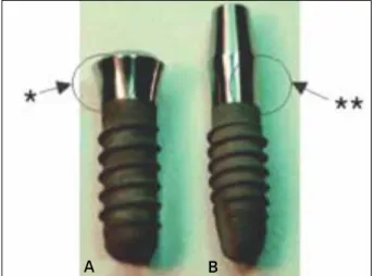
출시 중인 일체형 임플란트는 일반적으로 직선형 경부 를 가지는데, 대표적 사례를 Fig. 1 (NobelDirect�
3.0, Nobel Biocare, Gothenburg, Sweden)과 Fig. 2 (ITI
�, Straumann, Waldenburg, Switzerland)에 나타내었다. Fig. 2의 ITI 경우
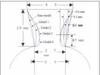
에서 보는 바와 같이 지대주와 고정체의 내측체결방식 에 이용되는 morse taper는 일체형 임플란트에 부여할 수 없으므로 간편한 직선형 디자인이 적용된 것으로 보인 다.본 연구에서는 일체형 임플란트의 치은관통부 측면에 곡선을 부여하였다. Fig. 3에 보인 바와 같이, 치은관통부 는 높이 2.8 mm, 상부 직경 4 mm, 하부 직경은 2.7 mm로 동일하며, Base model은 경부 측면이 직선이며, 다른 4가 지 모델은 곡선형 디자인을 가진다. Model-1, Model-2 및
Mode-3에서는 경부 측면의 함몰 (concavity) 정도가 미치
는 영향을 비교하기 위해 몸체의 나사부 (threaded part) 상 단 0.7 mm 위치에서 각각 0.1, 0.3, 0.6 mm의 함몰 깊이를 부여하였다. Mode-3과 Mode-4는 함몰부의 수직위치가 미치는 영향을 비교하기 위해 함몰 깊이는 0.6 mm로 동Fig. 1. A: A thin one piece implant model (NobelDirect�3.0, TiUnite� surface-99kb). B: NobelDirect�TiUnite�surface (111 kb) for flapless sur- gical procedure with soft tissue integration and immediate function.
*straight profile
Fig. 2. Comparison of actual morse-taper 2-Piece (A) and monoblock 1- Piece ITI�implants (B) on the left and right sides, respectively.
*concave profile, **straight profile
A B A B
일하나, 그 위치를 Mode-4에서는 나사부 (threaded part) 상 단에 근접하여 부여하였다.
치은관통부 측면은 구강내 생화학적 자극이 임플란트 외면을 통하여 치조정에 이르는 경로를 구성한다. 이 부 위가 곡선이면 직선 디자인보다 거리가 커지므로 생물 학적 폭경이 증가되는 효과가 있을 것이며, 정량적으로 추정하기는 어렵겠지만 곡선경로가 미생물이나 유해물 질의 이동의 관점에서도 직선보다 유리할 것으로 생각 된다. Fig. 4 에서는 디자인 차이에 따른 치은관통부 측면 의 거리를 비교하였다.
2. 축대칭 유한요소 모델
치은관통부 외에 임플란트의 기본외형과 나사산 형상 은 ITI 임플란트 (Fig. 2) 와 동일하게 설정, 매식부 직경
3.3 mm, 길이 10 mm의 임플란트가 폭경 7 mm 악골에 식
립된 형상을 축대칭으로 유한요소 모델링하였다 (Fig. 5).모델별 경부의 mesh모델은 Fig. 6에 나타낸 바와 같다. 응 력분포특성에 중요한 임플란트 경부골 곡면은 악골의 근원심 방향과 협설 방향 단면으로부터 가상적인 평균 곡률을 추론하여 spline 곡선을 이용, 굴곡없이 자연스런 형상으로 모델링하였다. 치밀골의 두께는 이전 연구37와
mesh
구성의 편의를 위해 0.8 mm로 가정하였으며 경부를 제외하고는 골/임플란트 계면은 모두 해면골로 가정 하였다.
유한요소 모델링과 해석에는 NISA II/DISPLAY III
(Engineering Mechanics Research Corporation, USA) 프로그
램을 사용하였다. Mesh 구성에는 NKTP type 34형 solid 요 소 (4각형 축대칭 요소, 요소당 절점수 8개)를 사용하여 임플란트 장축과 평행한 축대칭 하중은 물론 장축과 경 사각을 갖는 비축대칭 하중조건을 모두 해석할 수 있도 록 하였다.38Fig. 3. Five different cervical profiles. Base model: straight line, Model-1:
concavity 0.1 mm, Model-2: concavity 0.3 mm, Model-3 and Model-4:
concavity 0.6 mm.
Fig. 4. Comparison of the from top to bottom curvilinear distance along the external surface of transgingival part.
Fig. 5. A typical axisymmetric finite element mesh model (Base model).
For simplicity, soft tissue is not included in the model.
3. 물성치 (Material properties)
연구에 사용한 골 및 금속재료의 물성치는 여러 선학 들의 자료를 참조하였다 (Table I).39-41연조직의 경우 그 하 중 분담률을 무시할 수 있으므로 해석 전반에 걸쳐 모델 링에서 제외하였다.
4. 하중조건 및 경계조건
하중 크기는 Richter45가 소구치에 load cell을 부착하여 측정한 50 N 으로 정하였고, 작용 방향은 임플란트 장축 에 평행인 수직방향과 임플란트 장축에 30�를 이루는 사 선 방향의 두 가지로 설정하였다. 상용 저작하중이 15 -
50 N임을 감안하면
46,47단일 임플란트에 대한 하중 50 N은 특별한 경우를 제외하면 장기간 동안의 반복 저작하중 으로는 최대치로 간주할 수 있다. 하중은 치관의 중앙 위 치에 부여하였으며, 변위 경계조건으로 기저면 상의 모 든 절점에 Ux = Uy = 0 조건을 부여하여 완전히 고정하였 다 (Ux, Uy 는 각각 x축 및 y축 방향의 변위, Fig. 5).5. 응력 관찰점
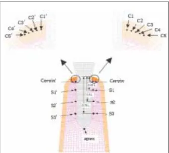
임플란트 주위골 응력의 상호 비교를 용이하게 하기 위해서 19군데의 응력관찰점 (stress monitoring point)을 설 정 하여 응력 변화 추이를 조사하였다 (Fig. 7). 응력관찰 점은 경부 치밀골에 10곳, 해면골에 9곳을 설정하였다.
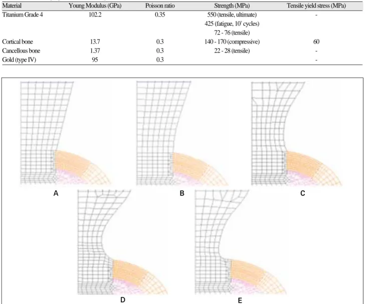
Fig. 6. The mesh model at the cervix of five different models. A: Base model, B: Model-1, C: Model-2, D: Model-3, and E: Model-4.
A B
D
C
E Table I. Mechanical properties (bone and implant materials)
Material Young Modulus (GPa) Poisson ratio Strength (MPa) Tensile yield stress (MPa)
Titanium Grade 4 102.2 0.35 550 (tensile, ultimate) -
425 (fatigue, 107cycles) 72 - 76 (tensile)
Cortical bone 13.7 0.3 140 - 170 (compressive) 60
Cancellous bone 1.37 0.3 22 - 28 (tensile) -
Gold (type IV) 95 0.3 -
경부 치밀골에 설정된 응력관찰점은 치밀골판의 중심면 상에 있는 절점들로, 임플란트의 표면으로부터 각각 0.2,
0.4, 0.6, 0.8, 1.0 mm 떨어진 위치이며, 해면골에서의 응력
관찰점은 경부 해면골과 고정체 높이의 각각 25%, 50%,75% 위치 및 근첨부에서 임플란트 외면에 가장 근접한
절점을 설정하였다.치밀골의 응력관찰점에서 기록된 응력은 특이점 문제 로 인해 계산이 어려운 경부골 응력 최대값 (peak stress)을 정량화하여 비교하기 위한 회귀분석에 이용되었다.37회 귀분석에는 SPSS WIN 12.0 (SPSS Inc. Chicago, IL, USA) 프로그램을 사용하였다.
결과
골내 매식부분의 직경은 3.3 mm, 길이는 10 mm로 동일 하나 경부 형상이 다르게 디자인된 5가지 모델의 일체형 임플란트가 7 mm 폭경의 악골에 식립된 경우에 대해 골 응력을 해석하였다. 하중조건은 두 가지로 수직하중 50
N과 임플란트 장축에 30�각도를 갖는 경사하중 50 N 조
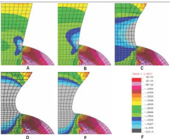
건이었다. 수직하중 하에서 Base Model 임플란트 및 악골 전체의 전형적인 응력분포를 나타내었다 (Fig. 8). 다른 모델들도 경부를 제외하고는 Base Model 과 유사한 응력 분포를 보였으며, 두 하중 조건하에서 경부 부위에서 응 력분포의 차이가 컸으므로 경부의 응력분포를 확대하여나타내었다 (Fig. 9, 10).
Fig. 9와 Fig. 10에서 보는바와 같이 경부 디자인 차이에
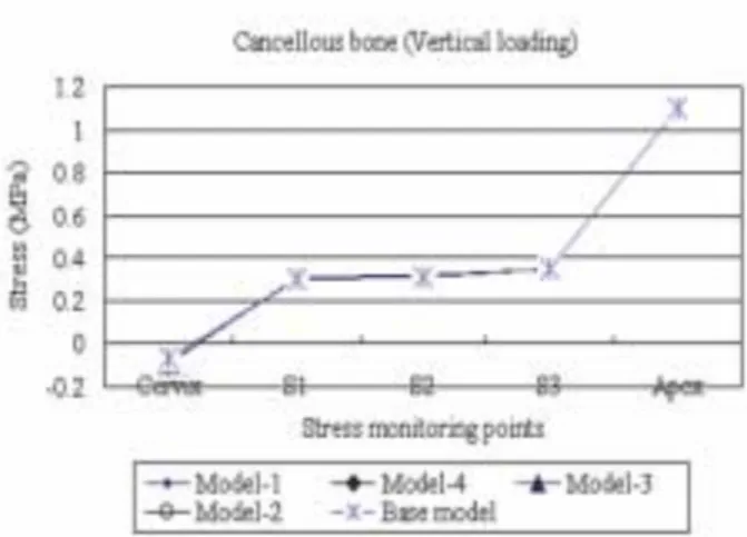
따라 임플란트내 응력분포가 차이를 보이는 것이 관찰 되었다. 상대적으로 골응력의 차이는 덜 현저하지만 경 부 피질골의 응력분포에도 차이가 관찰되었다.각 모델간의 응력분포 차이를 비교하기 위해 응력관찰 점에서 산출된 응력을 비교하였다 (Fig. 11 - 14). 경부 피 질골판과 해면골내의 임플란트 길이에 따라 좌우 측면 에 각각 5개씩의 응력관찰점이 설정되었으나 (Fig. 7), 수 직하중 하에서는 좌우측 응력이 같으므로 우측 응력만 나타내었다 (Fig. 11, 12). 반면, 임플란트가 경사력을 받을 경우에는 좌우측 응력에 차이가 생겼다. 경사력이 우측 방향으로 작용할 경우, 임플란트 우측에는 경사력의 수 직성분에 의한 압축응력과 경사력의 수평성분에 의한 굽힘응력의 압축성분이 서로 중첩되므로 응력수준이 높아지는 반면 임플란트 좌측에서는 경사력의 수평성 분에 의해 인장응력이 생겨서 수직력에의한 압축응력 을 상쇄하므로 응력이 낮아지는 것을 관찰할 수 있었다
(Fig. 13, 14).
Fig. 15와 16은 각각 수직력과 경사력 조건하에서 응력
관찰점에서 산출된 응력값에 근거하여 회귀분석방법으 로 구한 임플란트 경부골에서의 최대응력을 모델별로 비 교하였다. 그 결과는 선형, 2차 함수 분석 모두 각각의 모 델간의 최대응력의 상대 비교시 유사함을 나타내었다.Fig. 7. Stress monitoring points; 5 points at the either of right and left sides in the mid plane of cervical cortical plate, which are 0.2, 0.4, 0.6, 0.8, and 1.0 mm distant from the bone/implant interface, and 5 points in the either side along the length of the implant, i. e. located at the cervix, 0.25 L, 0.5 L, 0.75 L and the apex. (L= length of the threaded part)
Fig. 8. Typical overall stress distribution in the implant/bone complex (Base model subject to a vertical load of 50 N).
Fig. 9. Stress distribution at the cervix of five different models subject to a vertical load of 50 N.
A: Base model, B: Model-1, C:
Model-2, D: Model-3, and E:
Model-4, F: Stress band.
Fig. 10. Stress distribution at the cervix of five different models subject to a obliquely acting load of 50 N at an angle of 30° to the long axis of implant. A: Base model, B: Model-1, C: Model-2, D: Model-3, and E: Model-4, F:
Stress band.
A B
D
C
E F
A B
D
C
E F
Fig. 11. The maximum compressive stress distribution in the cortical bone surrounding the five different models subject to a vertical load of 50 N.
Fig. 12. The maximum compressive stress distribution in the cancellous bone surrounding the five different models subject to a vertical load of 50 N.
Fig. 13. The maximum compressive stress distribution in the cortical bone surrounding the five different models subject to an obliquely acting load of 50 N at 30° to the implant’s long axis.
Fig. 14. The maximum compressive stress distribution in the cancellous bone surrounding the five different models subject to an obliquely acting load of 50 N at 30�to the implant’s long axis.
Fig. 15. The peak stress at the cervical region of five different implant mod- els subject to a vertical load of 50 N estimated by a regression analysis.
Fig. 16. The peak stress at the cervical region of five different implant models subject to an obliquely acting load of 50 N at 30° to the implant’s long axis is estimated by a regression analysis.
고찰
임플란트 개발초기에는 주로 2 단계 수술을 통해 식립 되었으나 이제 1 단계 수술방식이 임상에 많이 활용되고 있다. 임플란트 시술방식의 변천은 환자의 불편과 임상 가의 수술부담을 줄이려는 필요성과 함께 임플란트 디 자인 변화와도 연관성이 깊다.
임플란트 경부의 디자인은 고정체와 지대주를 체결하 는 방식에 의해 결정된다. 2 단계 수술 방식은 1, 2차 수술 사이의 기간, 즉 임플란트를 식립한 후 임플란트/골 계면 에서 골유착이 진행되는 3 - 6개월의 기간 동안 상부에 피 판을 덮어서 생물학적 자극이나 구강하중에 의한 자극 을 차단하여 안정성을 높인다. 이때 고정체와 상부 피판 간의 상호작용을 최소화하기 위해선 골외부로 노출되는 부위의 높이가 최소화되는 것이 유리하다. 이같은 경부 디자인과 더불어 external형 지대주 체결방식이 전통적으 로 활용되었다. 반면 1 단계 수술로 임플란트 식립을 완 성하는 경우, 고정체 상부가 치은을 관통하여 구강에 노 출되어야 하며 이 경우에는 internal형 지대주 체결방식이 우세하다. Morse taper를 갖는 ITI의 solid screw 임플란트 가 대표적인 예인데, external형이 지대주 나사 풀림 등의 결함48을 자주 일으키는데 비해 internal형은 지대주 체결 의 안정성이 더 높은 것으로 보고되고 있다.49-51
최근에는 임플란트 식립 즉시 기능력을 부여하여 골/
임플란트 계면의 골유착의 조기완성을 도모하려는
immediate loading 개념이 등장하고, 이 경우도 delayed loading의 경우와 유사한 수준의 성공률을 기대할 수 있
는 것으로 보고되었다.52이 개념에서는 임플란트/골 계 면의 골유착이 완성되는 기간을 별도로 기다릴 필요가 없으므로 임상가가 임플란트 고정체와 지대주를 조립하 는 과정을 생략할 수 있어서 일체형임플란트 디자인이 가능해졌다.고정체/지대주 일체형 디자인은 임플란트 치은관통부 의 직경을 필요에 따라 변화시킬수 있는 장점도 있다. 비 일체형 임플란트에 있어서는 고정체와 지대주를 연결되 는 나사기구 (screw mechanism)구현을 위해 경부의 직경 이 일정 수치 이상이 되어야 한다. 임플란트 직경이 약 3
mm 이하가 되면 지대주 나사가 지나치게 가늘어지거나
혹은 고정체의 측벽 두께가 얇아져 파절이 일어나기 쉬 울 수 있다. 일체형 임플란트의 경우 이같은 제약에서 비 교적 자유스럽다.Fig. 9, 10에 도시한 바와 같이 임플란트 자체의 응력분
포는 경부에서 큰 차이를 보였으며 이는 임플란트 경부 의 직경 차이에 따른 당연한 결과로 보인다. 그러므로 임플란트 재질의 최대응력의 관점에서 하중조건에 따른 재료강도학적인 분석이 필요할 것이다. 본 연구에서는 골응력에 주목하였으며 경부디자인이 임플란트 자체의 강도에 미치는 영향에 대해서는 제한된 범위내에서 평 가를 수행하였다.
임플란트 응력이 가장 큰 경우는 Model-4에 경사력이 작용하는 경우이었다. 이때의 티타늄 재질의 파손을 결 정하는 최대 인장응력은 경사력이 작용하는 반대편 즉 임플란트의 좌측면에서 약 280 MPa에 달하였다 (Fig. 17).
이 크기는 티타늄 grade 4 재질의 피로강도 425 MPa (Table
I)에 비해 약 50%의 안전 여유가 있으므로, 경사력 50 N
정도의 하중은 임플란트의 피로파괴를 유발하지 않을 것으로 추정할 수 있다. 경사력이 임플란트 장축과 30�를 유지한다면, 임플란트에 107 번의 반복 작용할 수 있는 최대하중은 약 75 N 정도이다. 그러나 치축과의 경사각 이 커진다면 굽힘모멘트의 급격한 증가와 그에 따라 응 력의 증가가 유발되므로 임플란트의 식립각 및 교합조 정이 응력관리의 측면에서 대단히 중요할 것으로 사료 된다.Fig. 9, 10의 응력분포도와 Fig. 11 - 14에서 보는 바와 같
이 경부치밀골내 응력의 크기는 임플란트 외벽으로 부 터 떨어진 거리에 역비례한다. 따라서 경부골의 최대응 력은 임플란트/골 계면에서 발생할 것이며, 이러한 응력 의 거리에 따른 역비례관계를 선형함수와 이차함수의 두 가지로 가정하여 임플란트/골 계면에서의 응력값을 추산하였다. 두 하중조건에서 모두 이차함수 사용시 응 력이 더 크게 산출되었지만, Fig. 15, 16에서 보는 바와 같Fig. 17. Stress distribution at the implant cervix subject to an obliquely acting load of 50 N at an angle of 30�to the long axis of implant (maxi- mum tensile stress, Model-4).
되는 Model-4 간의 차이는 약 5% 정도였다. 이 정도 수준 의 응력감소가 임상적으로 또는 임플란트의 장기 예후 에 어떤 차이를 가져올지는 예단하기 어렵다. 그러나 이 러한 응력 감소와 더불어 치은관통면의 곡선설계에 따 라 골의 상부와 구강환경간의 거리 증가의 효과가 중첩 될 것이므로 경부디자인의 효과가 배가될 수 있을 것으 로 기대되며 이의 확인을 위해 향후의 동물실험과 임상 적 연구가 더 필요할 것으로 사료된다.
결론
유한 요소 해석을 통해 임플란트 경부의 형상이 임플 란트 주위골의 응력에 미치는 영향을 분석하기 위해 일 체형 임플란트를 선정하여 치은 관통부인 경부의 외형 모델 5가지에 수직하중 50 N과 장축에 30。각도를 갖는 경사하중 50 N을 설정하여 각각이 골응력에 미치는 영향 을 비교 분석하여 다음과 같은 결과를 얻었다.
1. 경부 치은관통부가 직선으로 설계된 Base Model에
서 경부치밀골의 응력이 최대였으며 경부에 함몰부 를 부여하여 곡선으로 설계한 4개의 모델에서는 골 응력이 감소되었다.2. 경부의 함몰부가 클수록 골응력의 큰 감소를 가져왔
으며, 함몰부의 수직위치가 치조정에 가까운 Model-4 가 Model-3 보다 응력감소효과가 더 컸다.
3. Base Model 과 Model-4 사이에서 최대응력의 차이가
가장 컸으며 그 크기는 응력값의 약 5%에 해당되었 다.참고문헌
1. Eriksson RA, Albrektsson T. The effect of heat on bone re- generation: an experimental study in the rabbit using the bone growth chamber. J Oral Maxillofacial Surg
2005;14:108-16.
6. Broggini N, McManus LM, Hermann JS, Medina RU, Oates TW, Schenk RK, Buser D, Mellonig JT, Cochran DL. Persistent acute inflammation at the implant-abutment interface. J Dent Res 2003;82:232-7.
7. Hermann JS, Buser D, Schenk RK, Cochran DL. Crestal bone changes around titanium implants. A histometric evaluation of unloaded non-submerged and submerged im- plants in the canine mandible. J Periodontol 2000;71:1412- 24.
8. Piattelli A, Vrespa G, Petrone G, Iezzi G, Annibali S, Scarano A. Role of the microgap between implant and abutment: a retrospective histologic evaluation in monkeys.
J Periodontol 2003;74:346-52.
9. Sanavi F, Weisgold AS, Rose LF. Biologic width and its re- lation to periodontal biotypes. J Esthet Dent 1998;10:157- 63.
10. Tarnow DP, Cho SC, Wallace SS. The effect of inter-im- plant distance on the height of inter-implant bone crest. J Periodontol 2000;71:546-9.
11. Hartman GA, Cochran DL. Initial implant position deter- mines the magnitude of crestal bone remodeling. J Periodontol 2004;75:572-7.
12. Oh TJ, Yoon J, Misch CE, Wang HL. The causes of early implant bone loss: myth or science? J Periodontol 2002;
73:322-33.
13. Chun HJ, Cheong SY, Han JH, Heo SJ, Chung, JP, Rhyu IC, Choi YC, Baik HK, Ku H, Kim MH. Evaluation of de- sign parameters of osseointegrated dental implants using fi- nite element analysis. J Oral Rehabil 2002;29:565-74.
14. Bozkaya D, Muftu S, Muftu A. Evaluation of load transfer characteristics of five different implants in compact bone at different load levels by finite elements analysis. J Prosthet Dent 2004;92:523-30.
15. Holmes DC, Loftus JT. Influence of bone quality on stress distribution for endosseous implants. J Oral Implantol 1997;23:104-11.
16. Kitagawa T, Tanimoto Y, Nemoto K, Aida M. Influence of cortical bone quality on stress distribution in bone around
dental implant. Dent Mater J 2005;24:219-24.
17. Petrie CS, Williams JL. Comparative evaluation of implant designs: influence of diameter, length, and taper on strains in the alveolar crest. A three-dimensional finite-element analysis. Clin Oral Implants Res 2005;16:486-94.
18. Sevimay M, Turhan F, Kilicarslan MA, Eskitascioglu G.
Three-dimensional finite element analysis of the effect of different bone quality on stress distribution in an implant- supported crown. J Prosthet Dent 2005;93:227-34.
19. Barbier L, Vander Sloten J, Krzesinski G, Schepers E, Van der Perre G. Finite element analysis of non-axial versus ax- ial loading of oral implants in the mandible of the dog. J Oral Rehabil 1998;25:847-58.
20. Kitamura E, Stegaroiu R, Nomura S, Miyakawa O.
Influence of marginal bone resorption on stress around an implant-a three-dimensional finite element analysis. J Oral Rehabil 2005;32:279-86.
21. Natali AN, Pavan PG, Ruggero AL. Analysis of bone-im- plant interaction phenomena by using a numerical ap- proach. Clin Oral Implants Res 2006;17:67-74.
22. Frost HM. A 2003 update of bone physiology and Wolff’s Law for clinicians. Angle Orthod 2004;74:3-15.
23. Melsen B. Biological reaction of alveolar bone to ortho- dontic tooth movement. Angle Orthod 1999;69:151-8.
24. Clelland NL, Ismail YH, Zaki HS, Pipko D. Three-dimen- sional finite element stress analysis in and around the Screw-Vent implant. Int J Oral Maxillofac Implants 1991;6:391-8.
25. Clelland NL, Gilat A. The effect of abutment angulation on stress transfer for an implant. J Prosthodont 1992;1:24-8.
26. Meijer HJ, Starmans FJ, Steen WH, Bosman F. Location of implants in the interforaminal region of the mandible and the consequences for the design of the superstructure. J Oral Rehabil 1994;21:47-56.
27. Hoshaw SJ, Brunski JB, Cochran GVB. Mechanical load- ing of Bra�nemark fixtures affects interfacial bone modeling and remodeling. Int J Oral Maxillofac Implants 1994;
9:345-60.
28. Isidor F. Histological evaluation of peri-implant bone at im- plants subjected to occlusal overload or plaque accumula- tion. Clin Oral Implants Res 1997;8:1-9.
29. Quirynen M, Naert I, van Steenberghe D. Fixture design and overload influence marginal bone loss and fixture suc- cess in the Branemark system. Clin Oral Implants Res 1992;3:104-11.
30. Jung ES, Jo KH, Lee CH. A finite element stress analysis of the bone around implant following cervical bone resorp- tion. J Korean Acad Implant Dent 2003;22:38-47.
31. Kitamura E, Stegaroiu R, Nomura S, Miyakawa O.
Biomechanical aspects of marginal bone resorption around osseointegrated implants: considerations based on a three- dimensional finite element analysis. Clin Oral Implants Res 2004;15:401-12.
32. Callan DP, Hahn J, Hogan B, Jenkins G, Krauser JT.
Implant failure. Implant Dent 2002;11:109-17.
33. Tada S, Stegaroiu R, Kitamura E, Miyakawa O, Kusakari H. Influence of implant design and bone quality on stress/strain distribution in bone around implants: a 3-di- mensional finite element analysis. Int J Oral Maxillofac Implants 2003;18:357-68.
34. Hansson S, Werke M. The implant thread as a retention el- ement in cortical bone: the effect of thread size and thread profile: a finite element study. J Biomech 2003;36:1247-58.
35. O’Brien, GR, Gonshor A, Balfour A. A 6-year prospective study of 620 stress-diversion surface (SDS) dental im- plants. J Oral Implantol 2004;30:350-7.
36. Gotfredsen K, Berglundh T, Lindhe J. Bone reactions adja- cent to titanium implants with different surface characteris- tics subjected to static load. A study in the dog (II). Clinl Oral Implants Res 2001;12:196-201.
37. Yu W, Jang YJ, Kyung HM. Combined influence of im- plant diameter and alveolar ridge width on crestal bone stress: a quantitative approach. Int J Oral Maxillofac Implants 2009;24:88-95.
38. NISA II / DISPLAY III User’s Manuel, Engineering Mechanics Research Corporation (EMRC).
39. Borchers L. Reichart P. Three-dimensional stress distribu- tion around a dental implant at different stages of interface development. J Dent Res 1983:62:155-9.
40. Collings EW. The physical metallurgy of titanium alloys.
Metals Park (OH): Americal society of metals. 1984.
41. Craig RG. Restorative dental materials. 8thed. St. Louis (MO):Mosby:1989. p84.
42. Nicolella DP, Lankford J, Jepsen KJ, Davy DT. Correlation of physical damage development with microstructure and strain localization in bone. Am Soc Mechanical Engineers 1997;35:311-2.
43. Koh CS, Lee MS, Choi KW. Improved stress analyses of dental systems implant by homogenization technique. J Korean Acad Periodontol 1997;27:263-90.
44. Lavernia CJ, Cook SD, Weinstein AM, Klawitter JJ. An analysis of stresses in a dental implant system. J Biomech 1981;14:555-60.
45. Richter EJ. In vivo vertical forces on implants. Int J Oral Maxillofac Implants 1995;10:99-108.
46. Anderson DJ. Measurement of stress in mastication. I. J Dent Res 1956;35:664-70.
47. Anderson DJ. Measurement of stress in mastication. II. J Dent Res 1956;35:671-3.
48. Hanses G, Smedberg JI, Nilner K. Analysis of a device for assessment of abutment and prosthesis screw loosening in oral implants. Clin Oral Implants Res 2002;13:666-70.
49. Sutter F, Weber HP, Sorensen J, Belser U. The new restora- tive concept of the ITI dental implant system: design and engineering. Int J Perio Rest Dent 1993;13:409-31.
50. Norton MR. An in vitro evaluation of the strength of a 1-
Finite element analysis of peri-implant bone stress influenced by cervical module configuration of endosseous implant
Jae-Min Chung1, DDS, MSD, Kwang-Heon Jo2, DDS, MSD, PhD, Cheong-Hee Lee2, DDS, MSD, PhD, Wonjae Yu3, DDS, MS, PhD, Kyu-Bok Lee4*, DDS, MSD, PhD
1Graduate Student, 2Professor, 4Assistant Professor, Department of Prosthodontics, School of Dentistry, Kyungpook National University
3Associate Professor, Department of Orthodontics, School of Dentistry, Kyungpook National University
Statement of problem: Crestal bone loss, a common problem associated with dental implant, has been attributed to excessive bone stresses. Design of implant’s transgingival (TG) part may affect the crestal bone stresses. Purpose: To investigate if concavely designed geometry at a dental implant’s TG part reduces peri-implant bone stresses.
Material and methods: A total of five differently configured TG parts were compared. Base model was the ITI one piece implant (Straumann, Waldenburg, Switzerland) char- acterized by straight TG part. Other 4 experimental models, i.e. Model-1 to Model-4, were designed to have concave TG part. Finite element analyses were carried out using an axisymmetric assumption. A vertical load of 50 N or an oblique load of 50 N acting at 30�with the implant’s long axis was applied. For a systematic stress comparison, a total of 19 reference points were defined on nodal points around the implant. The peak crestal bone stress acting at the intersection of implant and crestal bone was estimated using regression analysis from the stress results obtained at 5 reference points defined along the mid plane of the crestal bone. Results: Base Model with straight configuration at the transgingival part created highest stresses on the crestal bone. Stress level was reduced when concavity was imposed. The greater the concavity and the closer the concavity to the crestal bone level, the less the crestal stresses. Conclusion: The transgingival part of dental implant affect the crestal bone stress. And that concavely designed one may be used to reduce bone stress. (J Korean Acad Prosthodont 2009;47:394-405)
Key words: One-piece implant, Transgingival design, Finite element method, Crestal bone stress
*Corresponding Author: Kyu-Bok Lee
Department of Prosthodontics, School of Dentistry, Kyungpook National University, 188-1, Samduk 2, Jung-Gu, Daegu, 700-721, Korea +82 53 600 7651: e-mail, [email protected]
Article history
Revised June 19, 2009/ Last Revision September 10, 2009/ Accepted September 15, 2009