I. Introduction
The underwater acoustic communication channel is known to exhibit a frequency selective channel by multi-path delay spread in a multipath channel such as the shallow water. The ISI (Inter-Symbol Interference) occurs
due to multiple reflections from the water surface and the seabed affected by the reflected waves, resulting in degradation of underwater acoustic communication performance in the shallow water.[1-3] As the channel’s bandwidth becomes narrow due to the influence of the ISI, it shows the frequency selective channel.[4-6] For the proper underwater acoustic communication in these situations, we concentrated on the waveform shaping filters which is known helpful to prevent ISI.[7,8] So, we investigate the
Performance evaluation of a modified waveform shaping filter for the underwater acoustic communication
수중 음향 통신에 있어서 변형된 파형 정형 필터의 성능 평가
Kyu-Chil Park,1† Hyunsoo Jeong,1 and Jihyun Park1 (박규칠,1† 정현수,1 박지현1)
1Department of Information and Communications Engineering, Pukyong National University (Received November 8, 2018; revised December 18, 2018; accepted January 23, 2019)
ABSTRACT: The transmitted acoustic signals are severely influenced by multiply reflected signals from boundaries, such as sea surface and bottom in the shallow water. Very large reflection signals from boundaries cause inter-symbol interference so that the performance of the underwater acoustic communication is degraded.
Usually, the waveform shaping filters are used to prevent the reflected signals under this kind of acoustic channel.
Especially, the raised cosine filter is widely used, which can also be used to restrict the bandwidth of the transmitted signal. In this study, we evaluate the raised cosine filter for image data transmission in the shallow water, and propose a new modified raised cosine filter. The QPSK (Quadrature Phase Shift Keying) system is used for the underwater acoustic communication simulations with different distances and symbol rates. As a result, the bit error rate was reduced from the minimum 1.0 % to the maximum 32 %.
Keywords: Waveform shaping filter, Underwater acoustic communication, QPSK (Quadrature Phase Shift Keying) system, Raised cosine filter
PACS numbers: 43.30.Wi, 43.60.Dh, 43.60.Kx
초 록: 천해에서 전송되어진 음향 신호는 해수면 및 바닥과 같은 경계로부터의 다중 반사파에 의해 많은 영향을 받는다. 경계로부터의 매우 큰 반사 신호는 심볼 간 간섭을 일으켜 수중 음향 통신의 성능을 저하시키는 요인이 된다.
일반적으로 이러한 종류의 음향 채널에서 반사된 신호를 방지하기 위해 파형 정형 필터를 사용되고 있다. 특히 상승 코사인 필터가 널리 사용되며, 이 필터는 전송 신호의 대역폭을 제한하는 데에도 사용된다. 본 연구에서는 천해에서 영상 데이터 전송을 위한 상승 코사인 필터를 평가하며, 이를 바탕으로 새로운 수정된 상승 코사인 필터를 제안하고 평가 하였다. 수중 음향 통신 시뮬레이션에 사용된 통신 시스템은 직교 위상천이변조(Quadrature Phase Shift Keying, QPSK) 시스템이고, 송수신 거리와 심볼율을 달리하여 수행한 결과, 최저 1.0 %에서 최고 32 %의 에러 감소율을 보였다.
핵심용어: 파형 정형 필터, 수중음향통신, 직교위상천이변조, 상승 코사인 필터
†Corresponding author: Kyu-Chil Park ([email protected]) Department of Information and Communications Engineering, Pukyong National University, 45 Yongso-ro, Nam-gu, Busan 48513, Republic of Korea
(Tel: 82-51-629-6237, Fax: 82-51-629-6210)
effect of waveform shaping filter on the output signal of the transmitter on the underwater acoustic communication.
The applied communication system is the QPSK (Quadrature Phase Shift Keying) system[9] which has four different states in each symbol transmission. For the investigation of the effects of waveform shaping filters, the raised cosine filters are applied with three different roll-off factors.[8,10]
And we suggest and evaluate a modified raised cosine filter on the same communication condition. The perfor- mance of the modified raised cosine filter was found that the attenuation of the side-lobe level was more than -10 dB compared with other raised cosine filters at same time length and same frequency bandwidth.
II. QPSK system and waveform shaping filter
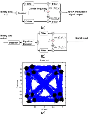
The QPSK modulation and demodulation system is one of the digital communication systems. There are two channels - I channel and Q channel - in the QPSK system as shown Fig. 1(a) and (b). The transmitted signal is
demodulated separately to two output signals using cosine signal or sine signal with same carrier frequency of modulation system. And then output signals are converted to 4 states sequences [00 01 10 11] through the decision processor for each channel with the phase variation shown as Fig. 1(c).
In Fig. 1(a) and (b), there are some filters on the behind of the carrier signal multiplying in the modulation and on behind of the carrier recovery in the demodulation, it is called the matched filter which has three reasons to be used. If the phase varies a 180°, the phase inverted time signal will ask very rapid response on the transducer. But it is very hard jobs on common analogue device, so that it is the first reason why we use some filter. The second reason is that the bandwidth of the signal might be limited on digital multi-carrier modulation method like as OFDM (Orthogonal Frequency-Division Multiplexing). The last reason is to detect and decide high probability without ISI on demodulated signal. For these reasons, it is commonly used the raised cosine filter as follows,[7,8]
cos , (1)
where , , mean the sinc function, the roll-off factor, and the reciprocal of the symbol-rate. It comes from the sinc function and cosine function. If the roll-off factor
is zero, the impulse response would be just sinc function with very strict band limit in the frequency domain.
The time signal and frequency responses represented according to the roll-off factor in Fig. 2. In Eq. (2), as the range of is set from -3 to 3 with intervals, all the length of the waveform shaping filter are chosen by 6×T.
Each number of (∙) means the roll-off factor. Those of solid line, dash-single dotted line, and dashed line are chosen by 0.0, 0.5, and 1.0, respectively. The symbol ○ means the cutoff frequency given by -6 dB point in Fig.
2(b). Each first side-lobe level are represented by about -23 dB, -45 dB, and -57 dB according to the roll-off factor, respectively. It can be seen that as the roll-off fact
(a)
(b)
-1 -0.5 0 0.5 1
-1 -0.8 -0.6 -0.4 -0.2 0 0.2 0.4 0.6 0.8 1
Quadrature
In-Phase Scatter plot
(c)
Fig. 1. QPSK system, (a) modulation system, (b) demo- dulation system, and (c) its scatter plot.
increases, the attenuation of the first side lobe decreases, and the transition bandwidth becomes wider.
As the ideal filter. Since the ideal filter characteristic is the large attenuation of the side lobe and narrow transition bandwidth, a new filter is modified by combining a raised cosine filter and a rectangular window with the narrowest transition bandwidth among the window functions.
In Fig. 2, the dotted green line is a new modified raised cosine filter combined by a raised cosine filter (the length is to be 5×T owing to the range of is set from -3 to 3 with
intervals) and the rectangular window (the length is T), so that the length of filter is given by 6×T. The first side-lobe level is given by about -70 dB.
cos
, (2)
where * and rect means the convolution operator and rectangular window, respectively.
III. Configuration of the simulations
Fig. 3 shows the configuration of sea experiment and its sound velocity profile in shallow water located in the George Island near to Busan city in Korea. The range between a transmitter and a receiver is set to be 100 m, or 400 m. Each depth of the receiver and the transmitter are set to be 7 m and 10 m, respectively. The channel charac- teristics of the numerical simulation are obtained as Fig. 4 from this environment parameter as shown Fig. 3. We assumed that the channel impulse responses had only 5 signals as shown in Eq. (3) - direct, bottom reflected, surface reflected, bottom-surface reflected, and surface - bottom reflected signals.
, (3)
Relative Amplitude
(a)
Relative Amplitude
(b)
Fig. 2. Raised cosine filter according to the roll-off factor, (a) time signal and (b) frequency response.
Fig. 3. Experimental configuration.
0 0.5 1 1.5 2
-1 -0.5 0 0.5 1
t (msec)
Relative amplitude shallow
deep
(a)
0 0.5 1 1.5 2
-1 -0.5 0 0.5 1
t (msec)
Relative amplitude shallow
deep
(b)
Fig. 4. Experimental configuration, (a) impulse response at 100 m, (b) impulse response at 400 m.
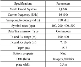
where Here, is the nth multi-path signal’s amplitude, is the nth multi-path delay time, and N is chosen by 4. The specific experimental parameters are given in Table 1. The transmitted image is the standard Lenna image consisting of 9,800 bits of data.
IV. Results and Discussion
For the check of the channel’s characteristic, the channel’s coherence bandwidths are calculated from Eqs.
(4) - (6). The average delays and are respectively given by [6,9]
, (4)
where is the amplitude of the nth path delay . From Eq. (4), the effective delay spread is given by
. (5)
The relationship between the effective delay spread and the channel’s coherence bandwidth is given by
≃ . (6)
The channel’s coherence bandwidth were calculated about 200 Hz and 760 Hz at 100 m and 400 m in shallow water, respectively. It means that 400 symbol rates per second (sps) on 100 m is only belonged to frequency-selective fading channels, so that the adaptive equalizer are required. Except this, all communication channels would be belonged to non-frequency-selective fading channels, and then only the phase compensation is required. Fig. 5 shows the constellations with carrier frequency 16 kHz in
Table 1. Simulation and experimental parameters.
Specifications Parameters
Mod/Demod. System QPSK
Carrier frequency (kHz) 16 kHz Sampling frequency (kHz) 128 kHz
Symbol rates (sps) 100, 200, 400, 800 Data Transmission Type Continuous
Tx and Rx range (m) 100, 400
Tx and Rx depth (m) 7, 10
Depth (m) ~15.7
Bottom property Mud
Data (bits) Image 9,800 bits
plate width 0.5 m
(a)
(b)
(c)
(d)
Fig. 5. Results of simulations according to roll-off factor, (a) Rcos (0.0), (b) Rcos (0.5), (c) Rcos (1.0), and (d) Rect+Rcos (0.5).
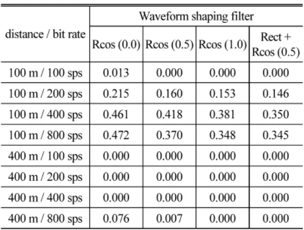
shallow sea - (a) Rcos (0.0), (b) Rcos (0.5), (c) Rcos (1.0), and (d) Rect+Rcos (0.5). From left top to right bottom, distance / sps orders were 100 m / 100 sps, 400 m / 100 sps, 100 m / 200 sps, 400 m / 200 sps, 100 m / 400 sps, 400 m / 400 sps, 100 m / 800 sps, and 400 m / 800 sps. It can be seen that as the roll factor increases, the constellation separates more clearly, and that the proposed filter is more concentrated. Table 2 shows the symbol per rate according to Fig. 5. Comparing the each result, the error rates were decreased in all cases. Also, it can be seen that the error decreases as the roll factor increases, and the proposed method shows the best results in all cases. This is attributed to the high attenuation and narrow transition bandwidth of the proposed filter.
V. Conclusions
In this paper, we investigated the effect of raised cosine waveform shaping filter on the underwater acoustic communication. The applied communication system was the QPSK system. For the investigation of the effects of waveform shaping filters, the raised cosine filters were applied with different roll-off factor, which are 0.0, 0.5, and 1.0, respectively. And modified raised cosine filter was proposed with combining rectangular window and raised cosine filter.
Comparing the each result, it can be seen that the error decreases as the roll factor increases, and the proposed
method shows the best results in all cases. The bit error rate was reduced from the minimum 1.0 % to the maximum 32 % compared with other raised cosine filters. This result is expected to be useful in an environment where the bandwidth due to reflections is narrowed, such as in the shallow water.
Acknowledgement
This work was supported by a Research Grant of Pukyong National University (2017 year).
References
1. T. C. Yang, “Properties of underwater acoustic commu- nication channels in shallow water,” J. Acoust. Soc. Am.
131, 129-145 (2012).
2. W. B. Yang and T. C. Yang, “High-frequency channel chara- cterization for M-ary frequency-shift-keying underwater acoustic communications,” J. Acoust. Soc.
Am. 120, 2615-2626 (2006).
3. T. B. Aik, Q. S. Sen, and Z. Nan, “Characterization of multipath acoustic channels in very shallow waters for communications,” Proc. of OCEANS'06 Asia-Pacific Conference, 1-8 (2007).
4. J. Park, J. R. Yoon, and J. S. Park, “Frequency and temporal coherence variation for sea surface fluctuation,”
Jpn. J. Appl. Phys. 48, 07GL03 (2009).
5. J. Park, K. C. Park, and J. R. Yoon, “Underwater acoustic communication channel simulator for flat fading,” Jpn. J. Appl. Phys. 49, 07HG10 (2010).
6. J. R. Yoon, K. C. Park, J. Park, and J. Park, “Perfor- mance comparison between packet and continuous data transmission using two adaptive equalizers in shallow water,” Jpn. J. Appl. Phys. 50, 07HG05 (2015).
7. K. Gentile, “The care and feeding of digital pulse-shaping filters,” RF Design, 25, 50-61 (2002).
8. Raised Cosine Filtering, https://kr.mathworks.com/help/comm/
examples/raised-cosine-filtering.html.
9. T. S. Rappaport, Wireless Communications: Principles and Practice, 2nd ed. (Prentice Hall, New Jersey, 2002), pp. 400.
10. Window Function, https://kr.mathworks.com/help/dsp/
ref/windowfunction.html?searchHighlight=window%20 function&s_tid=doc_srchtitle.
Table 2. Simulation results.
distance / bit rate
Waveform shaping filter Rcos (0.0) Rcos (0.5) Rcos (1.0) Rect +
Rcos (0.5) 100 m / 100 sps 0.013 0.000 0.000 0.000 100 m / 200 sps 0.215 0.160 0.153 0.146 100 m / 400 sps 0.461 0.418 0.381 0.350 100 m / 800 sps 0.472 0.370 0.348 0.345 400 m / 100 sps 0.000 0.000 0.000 0.000 400 m / 200 sps 0.000 0.000 0.000 0.000 400 m / 400 sps 0.000 0.000 0.000 0.000 400 m / 800 sps 0.076 0.007 0.000 0.000
Profile
▸Kyu‒Chil Park (박규칠)
He received his B.S. and M.S. degrees from the Department of Electronic Engineering from Pukyong National University, Busan, Korea, in 1993 and 1995, respectively. He received his Ph.D. degree from the Graduate School of Natural Science and Technology from Okayama University, Okayama, Japan, in 2000. Since 2002, he has been a professor in the Department of Information and Commu- nications Engineering, Pukyong National Uni- versity, Busan, Korea. His research interests include underwater acoustic signal processing, adaptive signal processing, numerical analysis, optimization, and inverse problems in engi- neering.
▸Hyunsoo Jeong (정현수)
He graduated with a BSc in Information and Communication Engineering from Pukyong National University in 2016. He took the MSc degree in engineering at Pukyong National University in 2018. He is currently studying for a doctoral degree. His research interest includes image processing, cellular automata, underwater acoustics and sonar.
▸Jihyun Park (박지현)
He received the B.S. degree in Telematics engineering from Busan National University in 2000, and the M.S. and Ph.D. degrees in Information and Communications Engineering from Pukyong National University in 2002 and 2008, respectively. Since 2019, he has been a senior engineer in the Institute of Acoustic and Vibration, Pukyong National University, Busan, Korea. His current research interests include underwater signal proces- sing and underwater acoustic communication system design.