1. Introduction
Pitting corrosion is one of the most destructive and in- sidious forms of corrosion. It can lead to accelerated fail- ure of structural components by perforation. Especially under stress, pitting corrosion is also an initiation site for crack of stress corrosion cracking or corrosion fatigue, and has great effects on the life of load carrying structure.
Pitting corrosion can be considered to consist of three stages: nucleation, metastable growth and stable growth [1]. The pit nucleation is a rare occurrence that happens extremely rapidly on a tiny scale. This is succeeded by a metastable stage in which the pit propagation is not yet fully stabilised but the growth is sustained by the sur- rounding and covering geometry of the passive surface from which the pit began [2]. The metastable stage may be succeeded by the stable stage, or the growth may termi- nate at the metastable stage.
Cellular automata are dynamic systems with local inter- actions in which space, time and other dynamic variables are discrete [3]. This property makes them a powerful tool for modeling physical, chemical systems. The cellular au- tomata are a kind of model based on mechanism [4].
Although the pitting corrosion is very complicated, the elementary electrochemical reactions that occur during the pitting corrosion processes are very clear [5]. This means that the cellular automata approach can be applied to mod- el the pitting corrosion processes. Many researchers have successfully used the cellular automata model to study the pitting corrosion [6-8].
The stress can lead to the increase of corrosion rate of metals [9]. First of all, the stress can increase the anodic dissolution current because it can increase lattice defects and the atomic activation energy. Furthermore, the anodic dissolution accelerates the degree of the local deformation of metals. Second, the breakdown of the passive film can occur in certain regions of the stress concentration, which leads to the preferential dissolution in the breakdown sites.
We have investigated the growth of metastable single pit under mechanical stress at a mesoscopic scale [10]. In this work, we study the interactions between corrosion pits for stainless steel under loading conditions by a cel- lular automata model coupled with finite element method.
2. Cellular Automata Model
A cellular automata model with Neumann neighborhood is performed in a two-dimensional space of 1024×1024.
There are five different kinds of sites involved in the proc-
Numerical Simulation of Interactions between Corrosion Pits on Stainless Steel under Loading Conditions
Haitao Wang†and En-Hou Han
Key Laboratory of Nuclear Materials and Safety Assessment, Institute of Metal Research, Chinese Academy of Sciences, Shenyang, 110016, China
(Received February 09, 2017; Revised February 09, 2017; Accepted April 18, 2017)
The interactions between corrosion pits on stainless steel under loading conditions are studied by using a cellular automata model coupled with finite element method at a mesoscopic scale. The cellular automata model focuses on a metal/film/electrolyte system, including anodic dissolution, passivation, diffusion of hydrogen ions and salt film hydrolysis. The Chopard block algorithm is used to improve the diffusion simulation efficiency. The finite element method is used to calculate the stress concentration on the pit surface during pit growth, and the effect of local stress and strain on anodic current is obtained by using the Gutman model, which is used as the boundary conditions of the cellular automata model. The transient current characteristics of the interactions between corrosion pits under different simulation factors including the breakdown of the passive film at the pit mouth and the diffusion of hydrogen ions are analyzed. The analysis of the pit stability product shows that the simulation results are close to the experimental conclusions.
Keywords: pitting corrosion, loading, cellular automata, finite element method
†Corresponding author: [email protected]
esses, which are the neural solution site W, the acidic solution site H, the metal site M, the passive site P , the salt film site S.
A layer of surface passive film is horizontally located at the middle position of cellular space. The upper part on the film is completely occupied by the W sites, and the lower part is occupied by the M sites. Two breakdowns at x=352 and 672 are produced on the film in order to simulate the initiation of double pits.
If an M site is in the acidic media, in which there is at least one H site in the neighborhood of current site, corrosion will happen at this site according to corrosion probability Pc=0.1. This M site is replaced by an H site, and an S site is placed on this H site. When an M site is in the neutral media, in which there are only the H sites in the neighborhood, passivation will happen at this site according to passivation probability Pp=0.1. This M site is replaced by a P site. When a P site in the acidic media, it will be dissolved according to dissolution proba- bility Pd=0.1. This P site is replaced by a W site.
The hydrolysis of the S sites can provide the hydrogen ions. If there are the W sites in the neighbours of one S site, these W sites are replaced by the H sites. When one S site reaches the number of H sites that it can provide Sn=4, it will be removed. The S sites will continually de- posit downwards by gravity until the downward sites are not the W or H sites.
In order to accelerate the diffusion simulation more effi- ciently, Chopard block algorithm [11] is adopted. The re- lation between simulation time interval and diffusion time interval can be given by the formula (1).
nl2
dt dt
D
= 0
2
4D dtD = a
(1)
where dt is the simulation time interval, dtD is the dif- fusion time interval, n is the number of block iteration, l is the block length, a is the lattice constant, D0 is the dif- fusion coefficient of hydrogen ions. dt, a and D0 is set as 2.5×10⁻³s, 25nm and 5.0×10⁻⁵ cm2/s, so n and l can be calcu- lated to 64 and 20 respectively. So the cell space is divided into equal square blocks of 64×64. The W and H sites in each block are randomly distributed. Subsequently, each block is shifted half a block down and half a block left, and the W and H sites in each block are randomly redistributed.
The elastic and plastic deformation can both increase the anodic activity of metals. Gutman built a model that describes the mechano-electrochemical effect of metals [10]. Far from equilibrium, the kinetic equations of the
anodic dissolution caused by the elastic and plastic de- formation during the strain hardening can be determined by:
Elastic deformation RT PV I
I m
n
= expD
Plastic deformation RT
V I
I m m
n
s e
e 1 exp
0 ÷÷ ø ö çç è æD +
= (2)
where I is the anodic current of deformation, In is the anodic current of no deformation, ΔP is the hydrostatic pressure, Vm is the molar volume, Δe is the plastic strain, e
0 is the onset of strain hardening, sm is the spherical part of macroscopic stress tensor depending on the applied load, R is the gas constant, T is the temperature.
The constant tensile stress of 200MPa is uniformly ap- plied on the right edge of the simulation cell. The stress on the pit surface is different because of the stress concentration. According to Gutman model, the mecha- no-electrochemical influence factor I/In of each point on the pit surface is determined by its hydrostatic pressure and equivalent plastic strain. The ABAQUS finite element software is used to obtain these values in real time by built-in python scripting language. In the finite element method, the Young modulus, the Poisson ratio and the yield strength for stainless steel are set as 210GPa,0.28 and 290Mpa respectively. Based on the magnitude of the influence factor calculated, the corresponding number of M sites continuously connected with current M site cor- roded is removed to account for the mechanoelec- trochemical effect.
3. Resutls and Discussion
The current transients and current density transients of metastable double pits of stainless steel under no loading and loading are shown in Fig. 1. The derivation of the current can be found elsewhere [8]. Under no loading, the current increases approximately with t2 during the ear- ly growth of pit, and the current density is approximately constant with time. It is close to the experimental data by Pistorius, Burstein [12] and Frankel [13]. Subsequently, the double pits coalescence about t=2s, and the current has a step increase. The current density gradually de- creases after coalescence. However, the current under loading is far higher than that under no loading. The cur- rent under loading increases approximately with t2.5 during the early growth of pit. Subsequently, the current also has a step increase about t=2s because of coalescence. The cur- rent density under loading at t<1.25 remains constant, which is consistent with that under no loading. Subsequently, the
current density increases with time, and begins to decrease after coalescence.
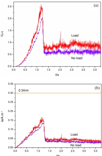
Fig. 2 shows the current transients and pit stability prod- ucts ia of metastable double pits under loading and no loading at Rt=1.25s and D0=5.0×10⁻⁵ cm2/s. The break- down time of pit cover Rt denotes the time that the rem- nant passive film and the corrosion products in the pit mouth are broken completely. D0 denotes the diffusion coefficient of hydrogen ions. After the breakdown of pit cover, both current under loading and no loading decrease sharply followed by reaching a plateau in Fig. 2a. This suggests that the metastable corrosion pits repassivate. The current under loading is a little higher than that under no loading. Because of the repassivation of corrosion pits, the pits do not coalescence. Fig. 2b shows the pit stability products ia in the same conditions. The pit stability prod- uct ia denotes the product of the current density i and the pit depth a. Pistorius and Burstein indicate that the requirement for stable pit growth of an open pit must be
above 0.3A/m [12]. The ia values under loading and no loading are below the critical value of 0.3A/m when the breakdown of pit cover occurs, so the metastable corrosion pits repassivate.
The current transients and pit stability products for metastable double pits at Rt=1.75s and D0=5.0×10⁻⁵ cm2/s are shown in Fig. 3. When the breakdown of pit cover occurs, the current under no loading drops slowly fol- lowed by a steady state, and the metastable corrosion pits repassivate. But there exists higher maintaining passivity current, so the corrosion pits still coalescence about 2.4s.
The current under loading decreases slowly followed by a rapid increase after the breakdown of pit cover. This indicates that the metastable pitting corrosion steps into the stable growth. The coalescence time becomes shorter under loading conditions, which is about 2.25s. Fig. 3b shows that the pit stability product under no loading is lower than the critical value of 0.3A/m, so the corrosion pits repassivate. However, that under loading reaches the (a)
(b)
Fig. 1 Current transients (a) and current density transients (b) of metastable double pits of stainless steel under loading and no loading.
(a)
(b)
Fig. 2 Current transients (a) and pit stability products (b) of metastable double pits of stainless steel under loading and no loading at Rt=1.25s and D0=5.0×10⁻⁵ cm2/s.
critical value of 0.3A/m, so the pits come into the stable stage. This shows that the simulation results are in close agreement with the experimental conclusions.
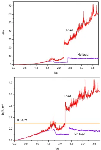
Fig. 4 shows the current transients and pit stability prod- ucts for metastable double pits at Rt=1.25s and D0=8.0×10⁻⁷ cm2/s. After the breakdown of pit cover, both current under loading and no loading do not decrease and continue to increase. The corrosion pits coalescence about t=2s. Subsequently, the current has a much faster increase.
The corrosion pits comes to stable growth. It can be seen in Fig. 4b that both pit stability products under loading and no loading are above the critical value of 0.3A/m.
According to Gutman model, both elastic deformation and plastic deformation can increase the anodic current, especially the plastic deformation. With the increase of the pit depth, the plastic strain on the pit bottom becomes much higher because of the stress concentration. It strong- ly increases the local anodic dissolution rate on the pit bottom. As a result, the current under loading is far higher than that under no loading, as shown in Fig. 1. With the
increase of the breakdown time of pit cover in Fig. 2 and Fig. 3, the anodic current peak becomes much larger when the breakdown of pit cover occurs. So the concentration of Fe cations in the solution is higher, and the salt film becomes richer. When the pit cover is broken, the salt film can release enough hydrogen ions to compensate the hydrogen ions that diffuse from the pit electrolyte to the bulk solution more easily. The corrosion pit can continue to grow because of autocatalytic nature, and do not repassivate. The decrease of the diffusion coefficient of hydrogen ions in Fig. 2 and Fig. 4 makes the diffusion rate more slowly, so the hydrogen ions stay in the pit more easily. This can provide the driving force for the growth of corrosion pits.
4. Conclusions
A cellular automata model coupled with finite element method is used to study the interactions between corrosion pits for stainless steel under loading conditions. The meta- stable double pits coalescence about t=2s, and the current
Fig. 3 Current transients (a) and pit stability products (b) for meta- stable double pits at Rt=1.75s and D0=5.0×10⁻⁵ cm2/s.
(a)
(b)
Fig. 4 Current transients (a) and pit stability products (b) for meta- stable double pits at Rt=1.25s and D0=8.0×10⁻⁷ cm2/s.
has a step increase. Under loading conditions, the meta- stable double pits at Rt=1.25s and D0=5.0×10⁻⁵ cm2/s repassivate. However, the metastable double pits at Rt=1.75s and D0=5.0×10⁻⁵ cm2/s, and at Rt=1.25s and D0=8.0×10⁻⁷ cm2/s steps into the stable growth. When the pit stability products are lower than the critical value of 0.3A/m in the simulation, the corrosion pits repassivate.
When the pit stability products are above 0.3A/m, the pits come into the stable growth. This suggests that the simu- lation results accord with the experimental conclusions.
Acknowledgments
This work was supported by the National Science and Technology Major Project (No. 2011ZX06004-009) and National Natural Science Foundation of China (No.
51001110).
References
1. G. S. Frankel, J. Electrochem. Soc., 145, 2186 (1998).
2. Gonzale-Garcia Y, G. T. Burstein, S. Gonzalez, and R.
M. Souto, Electrochem. Commun., 6, 637 (2004).
3. B. Chopard and M. Droz, Cellular Automata Modeling of Physical Systems, pp. 21-65, Cambridge University Press, Cambridge (1998).
4. H. T. Wang and E. H. Han, J. Mater. Sci. Technol., 28, 427 (2012).
5. G. Engelhardt and D. D. Macdonald, Corros. Sci., 46, 2755 (2004).
6. B. Malki and B. Baroux, Corros. Sci., 47, 171 (2005).
7. C. Vautrin-Ul, H. Mendy, A. Taleb, A. Chausse, J. Stafiej, and J. P. Badiali, Corros. Sci., 50, 2149 (2008).
8. L. Li, X. G. Li, C. F. Dong, and Y. Z. Huang, Electrochim.
Acta, 54, 6389 (2009).
9. E. M. Gutman, G. Solovioff, and D. Eliezer, Corros. Sci., 38, 1141 (1996).
10. H. T. Wang and E. H. Han, Electrochim. Acta, 90, 128 (2013).
11. B. Chopard, L. Frachebourg, and M. Droz, Int. J. Mod.
Phys. C, 5,, 47 (1994).
12. P. C. Pistorius and G. T. Burstein, Phil. Trans. Phys. Sci.
Eng., 341, 531 (1992).
13. G. S. Frankel, L. Stockert, F. Hunkeler, and H. Boehni, Corrosion, 43, 429 (1987).