http://dx.doi.org/10.5369/JSST.2020.29.3.149 pISSN 1225-5475/eISSN 2093-7563
Illumination Control in Visible Light Communication Using Manchester Code with Sync-Mark Signal
Seong-Ho Lee
+Abstract
In this study, we employed Manchester code for illumination control and flicker prevention of the light-emitting diode (LED) used in a visible light communication (VLC) system. In the VLC transmitter, the duty factor of the Manchester code was utilized for illu- mination control; in the VLC receiver, the spike signal from an RC-high pass filter was utilized to recover the transmitted signal whilst suppressing the 120-Hz noise arising from adjacent lighting lamps. Instead of the clock being transmitted in a separate channel, a sync- mark signal was transmitted in front of each data byte and used as the reference time for transforming the Manchester code to non- return-to-zero (NRZ) data in the receiver. In experiments, the LED illumination was controlled in the range of approximately 12–84%
of the constant wave (CW) light via changing of the duty factor from 10% to 90%. This scheme is useful for constructing indoor wire- less sensor networks using LED light that is flicker-free and presents capability for illumination control.
Keywords: Visible light communication, LED, Manchester code, duty factor, illumination control, flicker-free, spike signal.
1. INTRODUCTION
With the advances in semiconductor technology in recent years, many types of high-power visible light emitting diodes (LEDs) have been developed and are now widely used as light sources in various fields, such as indoor lighting, street lighting, automobile lighting, and billboard lighting. Compared with conventional light sources such as fluorescent or incandescent lamps, LEDs have high power conversion efficiency, a compact size, and their illumination can easily be controlled by adjusting the injection current. Owing to their high-speed modulation characteristics, LEDs are also being preferentially used as light sources for visible light communication (VLC). VLC is a new type of technology involving illumination and short-distance wireless communication conducted simultaneously using the same light source [1-3].
Visible light and conventional radio frequencies do not interfere with each other; thus, VLC can be considered a good transmission
method for enabling construction of safe wireless communication channels in environments where electromagnetic interference should be prevented [4,5].
In VLC systems, LEDs are the typical light sources, and photodiodes or image sensors are used as the detectors. The optical signal radiated from an LED is directly detected by a photodiode through free space. Because the light sources are used simultaneously for lighting and communication, VLC systems should be designed such that the illumination and communication functions do not affect each other [6]. Flicker and illumination control of LED light should be considered in the design of VLC systems. The average optical power should be kept constant during data transmission to prevent flickering of the LED light. Flickering is an unstable illumination condition in which the LED illumination is changed continuously, and this condition can make human sight inconvenient. Thus, VLC systems should be designed to prevent the flickering of LED light. Amplitude shift keying (ASK) or frequency shift keying (FSK) transmission with a subcarrier frequency are convenient transmission methods that can be employed to avoid LED flickering because the average optical power is maintained at a constant level during data transmission [7]. In base-band VLC systems with a relatively low data rate, special codes such as Manchester code can be effective methods to prevent LED flickering. Manchester code keeps the average optical power of LED light constant during data transmission. In this system, the clock synchronized with the transmitter should be Department of Electronics and IT Media Engineering, Seoul National
University of Science and Technology, 232 Gongneung-ro, Nowon-gu, Seoul, 01811, Korea
+
Corresponding author: [email protected] (Received: Apr. 6, 2020, Accepted: May. 25, 2020)
This is an Open Access article distributed under the terms of the Creative Commons Attribution Non-Commercial License(https://creativecommons.org/
licenses/by-nc/3.0/) which permits unrestricted non-commercial use, distribution,
and reproduction in any medium, provided the original work is properly cited.
connected to the receiver circuit to establish the reference time for the conversion of the Manchester code to the original non-return- to-zero (NRZ) code. In VLC systems, it is desirable that the illumination can be easily controlled by the user without affecting data transmission because the LED is also used as a lighting lamp.
In this paper, we used Manchester code with a sync-mark signal for data transmission in a VLC system. The sync-mark signal is transmitted in front of each data byte and is used in the receiver as the reference time for converting the Manchester code to the original NRZ code. Thus, in this system, a separate channel for clock transmission is not required. We used the duty factor of the Manchester code for illumination control. When the duty factor is fixed at a particular value, the average optical power is kept constant;
thus, the LED light is rendered flicker-free. When the user wishes to change the illumination, a new duty factor is selected by them. The LED illumination is almost linearly proportional to the duty factor.
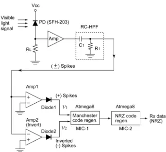
In the VLC receiver, the photodiode receives the signal light and recovers the transmitted data. When the photodiode is exposed to light from adjacent lighting lamps that are independent of the VLC system, the received signal can experience interference from the 120-Hz noise, even in the Manchester code transmission. If the noise is not negligible compared to the signal, errors can arise during data transmission, particularly in base-band VLC systems. The 120-Hz noise can easily be eliminated by a simple electrical filter; however, the signal from the transmitter is also distorted, which can cause difficulty in data recovery. To overcome this problem, we used an RC-high pass filter (HPF) in the receiver and the spike signals that appear at the leading and trailing edges of each data bit.
A positive spike signal appears at the leading edge of the bit where a “low-to-high” voltage transition occurs, while a negative spike signal appears at the trailing edge where a “high-to-low”
voltage transition occurs. Utilizing this phenomenon, the microprocessor in the receiver regenerated the original Manchester code by making “low-to-high” and “high-to-low”
voltage transitions at the points of the positive and the negative spikes, respectively. This scheme is simple to realize and is useful for constructing base-band VLC systems that are flicker-free, present capability for illumination control, and are robust against adjacent noise light interference.
2. ILLUMINATION CONTROL AND DATA RECOVERY METHOD
The illumination control method using the duty factor of the
Manchester code in the transmitter and the data recovery process in the receiver are described in this section.
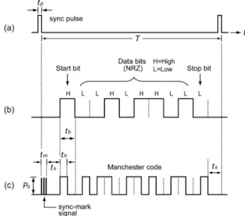
2.1 Illumination Control in the VLC Transmitter Illumination control of the LED light is achieved by changing the duty factor of the Manchester code, as illustrated in Fig. 1.
Fig. 1(a) shows the sync pulse that is used as the reference time for transforming the NRZ input data to the Manchester code in the VLC transmitter. In each period of the sync pulse, T, one byte of the NRZ input data is transmitted. Fig. 1(b) shows arbitrary NRZ input data in universal asynchronous receiver and transmitter (UART) format, which includes eight data bits, one start bit, and one stop bit. Fig. 1(c) shows the Manchester code for the NRZ input data. The Manchester code is used to modulate the LED light for flicker prevention and illumination control. The LED light modulated by the Manchester code becomes flicker-free because the average optical power of the LED light is kept constant. The duty factor of the Manchester code is changed by the user for LED illumination control. The duty factor is D = t
h/t
b, where t
bis one bit time, and t
his the duration of the high state in one bit time of the Manchester code.
In this system, we do not transmit the clock through a separate channel for recovery of the Manchester code as NRZ code in the receiver. Instead, the sync-mark signal is transmitted in front of each byte of Manchester code data, as shown in Fig. 1(c). The sync-mark signal is used as the reference time to recover the NRZ data from the Manchester code in the receiver. In order to distinguish the sync-mark signal from the Manchester code, the
Fig. 1. Generation of the Manchester code and the sync-mark signal:
(a) sync pulse, (b) NRZ input data, and (c) sync-mark signal
and Manchester code.
bit time of the sync-mark signal is designed to be shorter than that of the Manchester code with the smallest duty factor.
In these experiments, we used six bits “101010” with a bit time of 5 µs for the sync-mark signal. In this case, the length of the sync-mark signal (t
m) was 30 µs, while the bit time of the NRZ data was 104 µs in a 9.6 kbps UART data rate. Two stay times (t
s) exist between the sync-mark signal and the Manchester code in one byte of transmission, as shown in Fig. 1(c). In this modulation scheme, the average optical power of the LED light can be calculated as follows:
, (1)
where P
avgis the average optical power, P
0is the constant wave (CW) optical power, t
bis one bit time of data, D is the duty factor of the Manchester code, and t
mis the sync-mark signal time. The sync pulse period, T, is the sum of one pulse width (t
p), one sync- mark signal time (t
m), two stay times (t
s), and ten data bit times including one start bit and one stop bit involved in a byte transmission. That is,
(2) By substituting Equation (2) into (1), the average optical power normalized to CW power level becomes
. (3)
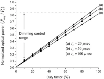
In Equation (3), we can see that the illumination of the LED light can be controlled by changing the duty factor, D. Fig. 2
shows the relationship between the average optical power and the duty factor of the Manchester code.
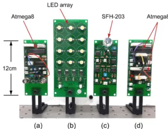
In Fig. 2, the three straight lines are the results of Equation (3), and the symbols ( ■, ●, ▲) are the measured results. In measuring the optical power, we used a 3 × 4 LED array composed of twelve 1 W white LEDs. The LED optical power density was measured using an optical power meter (OMM-6810B). The CW optical power density of the LED array was measured to be P
0= 1.06 W/
m
2at a distance of 1 m from the LED array. In measurements and calculations, we used a sync pulse width t
p= 10 µs, sync-mark signal time t
m= 30 µs, and one data bit time t
b= 104 µs for a UART data rate of 9.6 kbps. The stay time (t
s) between the sync- mark signal and the Manchester code data was used as a parameter. In Fig. 2, curves (a), (b), and (c) are for stay times of t
s= 20, 50, and 100 µs, respectively. The corresponding illumination control ranges were measured to be (a) 12% to 84%, (b) 11% to 80%, and (c) 10% to 74%.
As seen in Fig. 2, the LED optical power increased almost linearly with the duty factor. As the stay time (t
s) decreased, the proportional slope and the illumination control range increased.
As shown in Fig. 2(a), the average optical power normalized to CW LED light (P
avg/P
0) was controlled from 12% to 84% as the duty factor (D) was changed from 10% to 90%.
2.2 Data Recovery in the VLC Receiver
In the VLC receiver, the photodiode (PD) detects the VLC signal sent by the transmitter. Because the PD is open to free space, it can be exposed to light from other lighting lamps installed near the transmitter or receiver. The lighting lamps in an office commonly use a 60 Hz power line and may emit 120-Hz noise light, which can cause interference during data transmission.
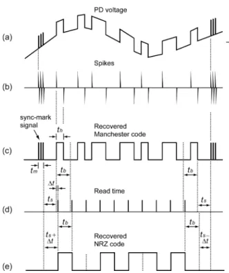
Especially in base-band VLC systems, this interference can be significant when the adjacent lighting is not negligible compared to the VLC transmitter. To overcome this problem, we used an RC-HPF at the PD output and the spikes appearing at the output of the filter to recover the transmitted data whilst eliminating the 120-Hz noise. Fig. 3 schematically shows the data recovery process using these spikes in the VLC receiver.
Fig. 3(a) is an example of the PD voltage in which the data waveforms from the transmitter and 120-Hz noise from adjacent lighting lamps are mixed. When the PD voltage passes through the RC-HPF, the 120-Hz noise is eliminated, and the rectangular data waveforms are changed to short spikes due to differential operation of the RC-HPF, as shown in Fig. 3(b). The positive and negative edge-spikes appear at the leading and trailing edges, )
10 5 . 0 ( 5
. 0
5 . 0 )
1 (
9 0 0 0
9 0 0
0
D t T t
D P t T t
P
t T t
dt P t T P P
b i b m
m
i h
m T
avg
+
=
⎟ ⎠
⎜ ⎞
⎝
⎛ +
=
⎟ ⎠
⎜ ⎞
⎝
⎛ +
=
=
∑
∫ ∑
=
=
b m s
p
t t t
t
T = + 2 + + 10
b m s p
b m b
avg m
t t t t
D t t T
D t t P
P
10 2
10 5 . 0 10
5 . 0
0