Comparison of cone-beam computed tomography cephalometric measurements using a midsagittal projection and conventional two-dimensional cephalometric measurements
Objective: This study investigated whether it is possible to use a two- dimensional (2D) standard in three-dimensional (3D) analysis, by comparing the angles and lengths measured from a midsagittal projection in 3D cone-beam computed tomography (CBCT) with those measured by 2D lateral cephalometric radiography (LCR). Methods: Fifty patients who underwent both LCR and CBCT were selected as subjects. CBCT was reoriented in 3 different methods and the measuring-points were projected onto the midsagittal plane. Twelve angle values and 8 length values were measured on both LCR and CBCT and compared.
Results: Repeated measures analysis of the variance revealed statistically significant differences in 7 angular and 5 linear measurements among LCR and 3 types of CBCT (p < 0.05). Of these 12 measurements, multiple comparisons showed that 6 measurements (ANB, AB to FH, IMPA, FMA, Co-Gn, Go-Me) were not significantly different in pairwise comparisons. LCR was significantly different from 3 types of CBCT in 3 angular (SN to FH, interincisal angle, FMIA) and 2 linear (S-Go, Co-ANS) measurements. The CBCT method was similar for all measurements, except for 1 linear measurement, i.e., S-N. However, the disparity between the mean values for all parameters was within the range of clinical measurement error. Conclusions: 3D-CBCT analysis, using midsagittal projection, is a useful method in which the 2D-LCR normative values can be used. Although the measurements changed with reorientation, these changes were not clinically significant.
[Korean J Orthod 2015;45(6):282-288]
Key words: Cephalometrics, Cone-beam computed tomography (CBCT), Diag- nosis and treatment planning, Reorientation
Pil-Kyo Jung Gung-Chol Lee Cheol-Hyun Moon
Department of Orthodontics, Gachon University Gil Medical Center, Incheon, Korea
Received March 3, 2015; Revised May 30, 2015; Accepted June 8, 2015.
Corresponding author: Cheol-Hyun Moon.
Professor, Department of Orthodontics, Gachon University Gil Medical Center, 21 Namdong-daero 774, Namdong-gu, Incheon 405-760, Korea.
Tel +82-32-460-3881 e-mail [email protected]
© 2015 The Korean Association of Orthodontists.
The authors report no commercial, proprietary, or financial interest in the products or companies described in this article.
This is an Open Access article distributed under the terms of the Creative Commons Attribution Non-Commercial License (http://creativecommons.org/licenses/by-nc/4.0) which permits unrestricted non-commercial use, distribution, and reproduction in any medium, provided the original work is properly cited.
pISSN 2234-7518 • eISSN 2005-372X
http://dx.doi.org/10.4041/kjod.2015.45.6.282
INTRODUCTION
In orthodontic diagnosis, lateral cephalometric radio- graphy (LCR) is an important diagnostic method for anal yzing the hard and soft tissue of the head and teeth. Since its introduction in 1931, LCR has been widely used in studies of oromaxillofacial growth and development.
1The cephalometric normative value, which has been accumulated through many studies, provides useful information in orthodontic diagnosis. However, it presents some issues, such as image magnification, errors in designating the measuring-point, and rotation of the head, due to the limitations of expressing a three- dimensional (3D) structure in two dimensions.
2,3Studies of 3D cone-beam computed tomography (3D-CBCT) are actively being pursued in orthodontics.
4-6CBCT emits less radiation than conventional CT, and it is less likely to result in magnified or distorted images than two-dimensional (2D) radiographic images.
7-9De- signation of the measuring-points in a multi-planar reconstruction (MPR) view has been shown to be high ly reproducible and reliable.
10On the other hand, con- sidering the large amount of information that CBCT provides, its utilization is limited and it still cannot re- place the widely used LCR, because studies of the nor -
mative value data are insufficient.
Many studies have examined how to derive 2D-LCR in- formation from 3D-CBCT. In some studies,
11-152D-LCR images extracted from 3D-CBCT data were compared with those obtained using conventional 2D-LCR. In other studies,
16-19landmarks were chosen directly from a 3D-CBCT image, without conversion to a 2D image, and these were then compared with those of conventional 2D-LCR. However, these studies did not consider the possible differences induced by the use of different re- orientation methods.
This study examined whether 2D normative values can be applied to CBCT analyses, without conversion to a 2D image, regardless of the type of reorientation method used.
MATERIALS AND METHODS
Subjects
This retrospective study was performed with insti- tutional review board approval of the Gachon University Gil Medical Center (GDIRB2014-07). Among the patients who visited the Department of Orthodontics in the Gil Medical Center from January 2012 to June 2013 with the chief complaint of orthodontic treatment, 437
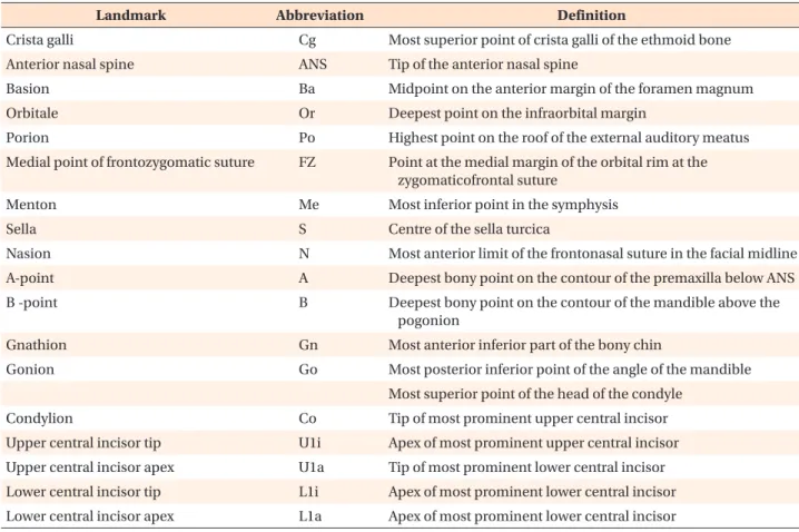
Table 1. Definitions of cephalometric landmarks used in this study
Landmark Abbreviation Definition
Crista galli Cg Most superior point of crista galli of the ethmoid bone
Anterior nasal spine ANS Tip of the anterior nasal spine
Basion Ba Midpoint on the anterior margin of the foramen magnum
Orbitale Or Deepest point on the infraorbital margin
Porion Po Highest point on the roof of the external auditory meatus
Medial point of frontozygomatic suture FZ Point at the medial margin of the orbital rim at the zygomaticofrontal suture
Menton Me Most inferior point in the symphysis
Sella S Centre of the sella turcica
Nasion N Most anterior limit of the frontonasal suture in the facial midline
A-point A Deepest bony point on the contour of the premaxilla below ANS
B -point B Deepest bony point on the contour of the mandible above the
pogonion
Gnathion Gn Most anterior inferior part of the bony chin
Gonion Go Most posterior inferior point of the angle of the mandible
Most superior point of the head of the condyle
Condylion Co Tip of most prominent upper central incisor
Upper central incisor tip U1i Apex of most prominent upper central incisor
Upper central incisor apex U1a Tip of most prominent lower central incisor
Lower central incisor tip L1i Apex of most prominent lower central incisor
Lower central incisor apex L1a Apex of most prominent lower central incisor
patients, who had undergone both LCR and CBCT on the same day due to impacted teeth, orthognathic sur- gery, temporomandibular joint disorder, etc., were sel- ected. Among those selected, 50 patients were chosen randomly using a randomization table. These subjects were 12 males and 38 females with an average age of 19.40 ± 6.40 years.
The subjects satisfied the following criteria:
- The patients had no facial deformity (e.g., cleft lip and palate or Menton deviation > 2 mm);
- The patients had intact upper and lower incisors and stable occlusion; and
- The patient’s LCR and CBCT images showed clear resolution, and were suitable for evaluation.
Acquisition of LCR and CBCT images
The exposure conditions for LCR were 68 kV and 5 mA, using a Proline XC model (Planmeca Oy, Helsinki, Finland). The head was positioned using an ear rod and head holder, and images were taken with the FH plane parallel to the surface of the earth. The LCR data was traced routinely using V-ceph 4.0 (Cybermed Inc., Seoul, Korea) and parameters were measured.
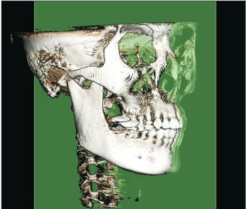
The exposure conditions for CBCT (3D eXam scanner;
KaVo Dental GmbH, Bismarckring, Germany) were set to 120 kV, 5 mA, and a 0.3 mm voxel size, and the scope of the shot was set to 230 × 170 mm. The subjects were seated comfortably maintaining a maximum intercuspal position and asked to stare at their own eyes in a mirror reflection, with the mirror located 1.5 m in front of
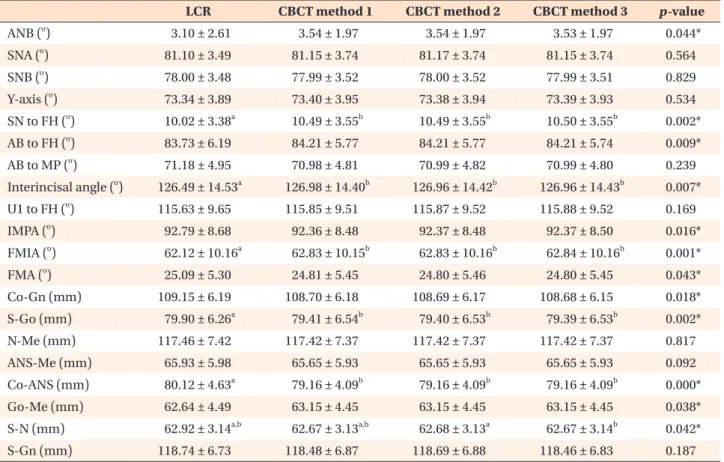
Table 2. Descriptive and statistical comparison of lateral cephalometric radiography (LCR) and cone-beam computed tomography (CBCT) reorientation methods
LCR CBCT method 1 CBCT method 2 CBCT method 3 p-value
ANB (
o) 3.10 ± 2.61 3.54 ± 1.97 3.54 ± 1.97 3.53 ± 1.97 0.044*
SNA (
o) 81.10 ± 3.49 81.15 ± 3.74 81.17 ± 3.74 81.15 ± 3.74 0.564
SNB (
o) 78.00 ± 3.48 77.99 ± 3.52 78.00 ± 3.52 77.99 ± 3.51 0.829
Y-axis (
o) 73.34 ± 3.89 73.40 ± 3.95 73.38 ± 3.94 73.39 ± 3.93 0.534
SN to FH (
o) 10.02 ± 3.38
a10.49 ± 3.55
b10.49 ± 3.55
b10.50 ± 3.55
b0.002*
AB to FH (
o) 83.73 ± 6.19 84.21 ± 5.77 84.21 ± 5.77 84.21 ± 5.74 0.009*
AB to MP (
o) 71.18 ± 4.95 70.98 ± 4.81 70.99 ± 4.82 70.99 ± 4.80 0.239
Interincisal angle (
o) 126.49 ± 14.53
a126.98 ± 14.40
b126.96 ± 14.42
b126.96 ± 14.43
b0.007*
U1 to FH (
o) 115.63 ± 9.65 115.85 ± 9.51 115.87 ± 9.52 115.88 ± 9.52 0.169
IMPA (
o) 92.79 ± 8.68 92.36 ± 8.48 92.37 ± 8.48 92.37 ± 8.50 0.016*
FMIA (
o) 62.12 ± 10.16
a62.83 ± 10.15
b62.83 ± 10.16
b62.84 ± 10.16
b0.001*
FMA (
o) 25.09 ± 5.30 24.81 ± 5.45 24.80 ± 5.46 24.80 ± 5.45 0.043*
Co-Gn (mm) 109.15 ± 6.19 108.70 ± 6.18 108.69 ± 6.17 108.68 ± 6.15 0.018*
S-Go (mm) 79.90 ± 6.26
a79.41 ± 6.54
b79.40 ± 6.53
b79.39 ± 6.53
b0.002*
N-Me (mm) 117.46 ± 7.42 117.42 ± 7.37 117.42 ± 7.37 117.42 ± 7.37 0.817
ANS-Me (mm) 65.93 ± 5.98 65.65 ± 5.93 65.65 ± 5.93 65.65 ± 5.93 0.092
Co-ANS (mm) 80.12 ± 4.63
a79.16 ± 4.09
b79.16 ± 4.09
b79.16 ± 4.09
b0.000*
Go-Me (mm) 62.64 ± 4.49 63.15 ± 4.45 63.15 ± 4.45 63.15 ± 4.45 0.038*
S-N (mm) 62.92 ± 3.14
a,b62.67 ± 3.13
a,b62.68 ± 3.13
a62.67 ± 3.14
b0.042*
S-Gn (mm) 118.74 ± 6.73 118.48 ± 6.87 118.69 ± 6.88 118.46 ± 6.83 0.187
Values are presented as mean ± standard deviation.
Repeated measures analysis of variance was used to compare between LCR and 3 different CBCT methods. Multiple comparisons, by the Bonferroni method, was used to further investigate the differences between groups.
a,b