Three-dimensional cone-beam computed tomography based comparison of condylar position and morphology according to the vertical skeletal pattern
8
0
0
전체 글
(2) Park et al • Condylar position and morphology. INTRODUCTION Condylar position and morphology are important features for temporomandibular joint (TMJ)-oriented orthodontic treatment planning. Orthodontic diagnosis, treatment, and therapeutic responses are also dependent on the skeletal pattern.1,2 Whether the occlusal relation ship affects the TMJ is controversial.3 The shape of the condyle and mandibular fossa has been reported to differ according to the type of malocclusion,3-5 but other studies have not demonstrated this relationship.3,6,7 The vertical facial pattern is known to influence the ma ximum occlusal force and masticatory muscle activities.8 Stringert and Worms 9 showed higher prevalence of internal derangement in patients with the hyperdivergent skeletal pattern. Relationships between the sagittal skeletal pattern and condylar position have been defined in several studies using lateral cephalometric radiographs and tomograms.10-12 Cohlmia et al.11 found that patients with skeletal Class III malocclusion tend to have more anteriorly positioned condyles than those with skeletal Class I malocclusion, but no difference in condylar po sition was discovered between Class I and Class II malo cclusions. Burke et al.10 also found no correlation bet ween facial morphology and anteroposterior condylar position in patients with skeletal Class II malocclusion. Diagnosis of temporomandibular disorders (TMDs) is complicated and requires comprehensive clinical and radiographic analyses.13 The complex structure of the TMJ makes radiographic examination difficult, and accurate diagnosis requires several types of radiographic imag es. Cone-beam computed tomography (CBCT) allows high-resolution imaging of TMJ structures with less radiation exposure than conventional spiral CT.14-17 Numerous efforts have been made to define relation ships between facial morphology and condylar charac. teristics through multiplanar CT examinations of the cond yle. 1-4,18-20 Several studies have emphasized the importance of condylar shape and volume for longterm stability after orthodontic treatment.21,22 Saccucci et al.21 reported that condylar volume and surface are correlated with mandibular divergence in young adults. However, little is known about the association between the vertical skeletal pattern and condylar position and morphology. The purpose of this study was to compare condylar position and morphology among different vertical skeletal patterns. The null hypothesis was that these features do not differ considerably according to the vertical skeletal pattern.. MATERIALS AND METHODS Diagnostic CBCT images of 60 adult patients (120 TMJs) who visited the orthodontic clinic of Hallym Uni versity Sacred Heart Hospital were reviewed. The study protocol was approved by the Hospital Ethics Review Committee (IRB 2013-1130). The subjects were 34 women and 26 men aged 20−40 years (mean age, 25.52±4.97 years) (Table 1). Patients were included if they did not have missing teeth except third molars, severe crossbite or openbite (overbite and overjet ≥ 0 mm), functional mandibular deviation due to occlusal interference, previous orthodontic treatment, clinical signs and symptoms of TMDs, previous TMD treatment, evident dental or facial asymmetry, congeni tal skeletal deformity such as cleft lip and palate, and history of trauma or general condition affecting the TMJ. For imaging, the patient was seated with the head in the natural head position, eyes focused on a point at the same level in a mirror, and teeth in centric occlusion. Table 1. Mean age, SN-GoMe, ANB, Angle’s classification of malocclusion and standard deviation (SD) for each group Variable. Group I. Patient (n). 20. Group II 20. Group III 20. Total 60. Age (yr). 24.95±4.38. 25.80±5.73. 25.80±4.91. SN-GoMe (o). 26.17±3.13. 34.43±3.41. 45.26±4.36. 0.87±3.44. 1.82±2.73. 4.49±2.91. Class I. 8 (40). 6 (30). 7 (35). 21. Class II. 4 (20). 5 (25). 12 (60). 21. Class III. 8 (40). 9 (45). 1 (5). 18. o. ANB ( ). 25.52±4.97. Angle Classification. Values are presented as number only, mean±standard deviation, or number (%). Group I, Hypodivergent; Group II, normodivergent; Group III, hyperdivergent. SN-GoMe, angle formed by Sella-Nasion plane and mandibular plane; ANB, A point-Nasion-B point angle to measure the relative position of maxilla to mandible.. www.e-kjo.org. http://dx.doi.org/10.4041/kjod.2015.45.2.66. 67.
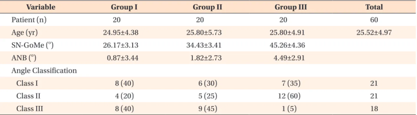
(3) Park et al • Condylar position and morphology. (maximum intercuspation). All scans were acquired with an Alphard VEGAunit (Asahi Roentgen, Kyoto, Japan) set at 80 kV, 5 mAs, 15-second scan time, and 0.39-mm3 voxel size. The exposure field was 200 mm in diameter and 179 mm in height. Images were transformed to DICOM (digital imaging and communications in me dicine) format and three-dimensionally reconstructed and analyzed through OnDemand 3D Application software (Cybermed, Seoul, Korea). The images were saved in C-mode and reoriented along the Frankfort horizontal plane on the basis of the right porion, right orbitale, and left orbitale. Both three-dimensional (3D) and cephalometric analyses were performed. The subjects were divided into three equal groups according to the angle formed by Sella-Nasion plane and mandibular plane (SN-GoMe): hypodivergent (SN-GoMe, < 22 o), normodivergent (SN-GoMe, 22 o−. 36o), and hyperdivergent (SN-GoMe, >36o) groups. One orthodontist performed all the measurements as described by Rodrigues et al.4,23 Sagittal slices showing a clear view of the condyle and mandibular fossa with a clear continuous line of cortical bone were examined. The position of each condyle was determined by mea suring the anterior, superior, and posterior joint spaces (Table 2, Figure 1). Depth of the mandibular fossa and angulation of the posterior wall of the articular tubercle were measured for identifying fossa morphology (Figure 1). Axial condylar morphology was assessed by mea suring the maximum medio-lateral width, maximum antero-posterior width, and angle between the condylar axis and the midsagittal plane (condyle head angle) (Figure 2). Sagittal condylar morphology was classified as normal, flattened osteophytic, and unclassified (Figure 3); normally shaped condyles were subclassified as oval. Table 2. Definition of the variables Measurement. Definition. Anterior joint space (mm). The shortest distance between the posterior wall of the articular tubercle and the most anterior point of the condylar head. Superior joint space (mm). The distance between the most superior point of the mandibular fossa and the most superior point of the condylar head. Posterior joint space (mm). The shortest distance between the posterior wall of the mandibular fossa and the most posterior point of the condylar head. Depth of mandibular fossa (mm) The distance between the most superior point of the mandibular fossa and the plane formed by the most inferior points of the articular tubercle and the postglenoid process Angulation of the posterior wall of the articular tubercle (o). The angle formed by the most superior point of the mandibular fossa, the most inferior point of the articular tubercle, and the most inferior point of glenoid process. Antero-posterior width of the condylar process (mm). The angle formed by the most superior point of the mandibular fossa, the most inferior point of the articular tubercle, and the most inferior point of glenoid process. Medio-lateral width of condylar process (mm). The mediolateral diameter of condylar process. Condyle axis angle (o). Angle between the medio-lateral plane of the condylar process and the midsagittal plane. 2 3. 1 5. 4. Figure 1. Sagittal measure ments. 1, Anterior joint space; 2, superior joint space; 3, pos terior joint spaces, 4, angu lation of the posterior wall of articular tubercle; 5, depth of the mandibular fossa. 68. http://dx.doi.org/10.4041/kjod.2015.45.2.66. www.e-kjo.org.
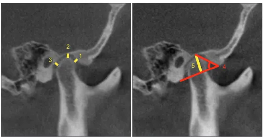
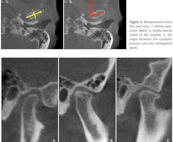
(4) Park et al • Condylar position and morphology. 1. 2. 3. Figure 2. Measurements from the axial view. 1, Antero-pos terior width; 2, medio-lateral width of the condyle; 3, the angle between the condylar process and the midsagittal plane.. A. B. C. Figure 3. Different shapes of condyles. A, Normal. B, Flattened. C, Osteophyte. and round on the basis of their shape in the axial view (Figure 4). Statistical analysis Another observer performed the same measurements in 30 randomly selected subjects, 10 from each group, to assess interobserver reliability. The measurements were repeated by both the observers after 2 weeks to assess intraobserver reliability. Pearson (intraobserver reliability) and intraclass (interobserver reliability) correlations were above 0.9 in all cases (Table 3). One-way analysis of variance (ANOVA) and Tukey post-hoc test were used to compare mean values among. www.e-kjo.org. http://dx.doi.org/10.4041/kjod.2015.45.2.66. the groups. The results were analyzed by using IBM SPSS Statistics software (release version 20.0; IBM Co., Armonk, NY, USA).. RESULTS Significant differences in right and left superior joint spaces, antero-posterior condyle width, medio-lateral condyle width, and condyle head angle were found between the hypodivergent and the hyp erdivergent groups (Tables 4 and 5). The hypodiv ergent and normodivergent groups showed a significant difference only in left condyle head angle (Tables 4 and 5). In. 69.
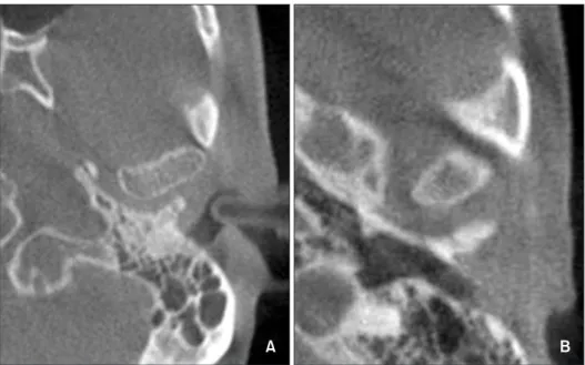
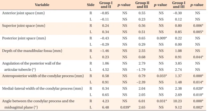
(5) Park et al • Condylar position and morphology. A. B. DISCUSSION. Table 3. Interobserver reliability Variable. Side. ICC. R. 0.98. L. 0.91. R. 0.93. L. 0.97. Posterior joint space (mm). R. 0.97. L. 0.92. Depth of mandibular fossa (mm). R. 0.96. L. 0.99. R. 0.92. L. 0.94. R. 0.98. Anterior joint space (mm) Superior joint space (mm). Angulation of posterior wall of articular tubercle (o) Anterior-posterior width of condylar process (mm) Medial-lateral width of condylar process (mm) Angle between condylar process and midsagittal plane (o). L. 0.93. R. 0.9. L. 0.99. R. 0.96. L. 0.97. R, Right; L, left; ICC, intraclass correlations coefficients.. the normodivergent and hyperdivergent groups, right antero-posterior condyle width and condyle head angle were significantly different (Tables 4 and 5). Findings of sagittal condylar morphology are shown in Table 6. The hypodivergent and hyperdivergent groups showed differences in normally shaped condyles: the hyperdivergent group had a large proportion of round condyles, whereas the hypodivergent group commonly had oval condyles (Table 7, Figure 4).. 70. Figure 4. Condylar shape di fference within the normal group. A, Oval. B, Round.. Abnormal condylar morphology was common in the hyperdivergent and hypodivergent groups. In parti cular, hyperdivergent facial morphology was asso ciated with smaller antero-posterior and medio-lateral condyle widths as well as narrower condyle head angle. Further, round condyles were found in patients with hyperdivergent facial morphology, whereas oval con dyles were noted in those with hypodivergent facial morphology. Therefore, the null hypothesis was rejected. The significantly smaller superior joint space in the hyperdivergent group indicates that the hyperdivergent skeletal pattern is associated with more superiorly posi tioned condyles. Similarly, Burke et al.10 found reduced superior joint space and posteriorly inclined condyles in preadolescent patients with skeletal Class II malocclusion and hyperdivergent tendency. They believe that this tendency reflects reduced condylar tissue, predicts de creased condylar growth potential, and eventually results in increased anterior facial height during growth and development of the nasomaxillary and dentoalveolar complex.10 The absence of a significant difference in anterior and posterior joint spaces indicate a lack of correlation between vertical facial morphology and an teroposterior condylar position. CBCT is a powerful tool for TMD diagnosis.13,17,24 CBCT scans provide multiplanar images of the condyle and surrounding structures and can be three-dimensionally reconstructed, allowing analysis of TMJ morphology, position, and dynamics.14,25-27 They enable easier and more accurate visualization of complicated anatomic structures with less radiation exposure, lower operating cost, and shorter scan time than conventional spiral. http://dx.doi.org/10.4041/kjod.2015.45.2.66. www.e-kjo.org.
(6) Park et al • Condylar position and morphology. Table 4. Measurements for the variables in all groups Variable. Side. Group I. Group II. Group III. R. 2.44 ± 0.67. 2.52 ± 0.65. 2.47 ± 1.02. L. 2.48 ± 0.71. 2.58 ± 0.81. 2.36 ± 0.86. R. 3.34 ± 0.60. 3.11 ± 0.90. 2.55 ± 0.80. *. L. 3.40 ± 0.74. 3.06 ± 0.91. 2.56 ± 0.77. *. R. 2.51 ± 0.65. 2.94 ± 0.75. 2.29 ± 0.59. L. 2.41 ± 0.53. 2.70 ± 0.83. 2.41 ± 0.53. R. 11.77 ± 1.26. 13.23 ± 1.63. 10.68 ± 1.22. L. 11.62 ± 1.29. 11.39 ± 1.23. 10.71 ± 0.92. R. 58.62 ± 5.25. 57.57 ± 7.30. 54.78 ± 6.86. L. 58.28 ± 5.66. 53.76 ± 6.41. 55.54 ± 5.91. R. 8.46 ± 0.94. 7.89 ± 0.93. 7.10 ± 1.03. *. L. 8.12 ± 0.97. 7.21 ± 1.16. 9.60 ± 1.17. *. R. 19.96 ± 2.48. 19.62 ± 2.92. 17.58 ± 2.69. *. L. 20.05 ± 2.68. 19.40 ± 2.79. 17.36 ± 2.92. *. R. 74.81 ± 5.55. 70.59 ± 5.50. 64.58 ± 9.91. *. L. 74.79 ± 5.59. 68.32 ± 9.28. 65.67 ± 9.09. *. Anterior joint space (mm). Superior joint space (mm). Posterior joint space (mm). Depth of the mandibular fossa (mm) o. Angulation of the posterior wall of the articular tubercle ( ). Anteroposterior width of the condylar process (mm). Medial-lateral width of the condylar process (mm) Angle between condylar process and the midsagittal plane (o). Sig. *. Values are presented as mean ± standard deviation. Group I, Hypodivergent; Group II, normodivergent; Group III, hyperdivergent; R, right; L, left. *p < 0.05, analyzed by one-way ANOVA and level of significance (Sig) among groups.. Table 5. Mean difference and level of significance tested with post-hoc test Variable. Side. Group I and II. p -value. Group II and III. p -value. Group I and III. p -value. Anterior joint space (mm). R. −0.85. NS. 0.55. NS. −0.30. L. −0.11. NS. 0.23. NS. 0.12. NS. Superior joint space (mm). R. 0.24. NS. 0.56. NS. 0.80. 0.006*. L. 0.34. NS. 0.51. NS. 0.85. 0.005*. R. −0.43. NS. 0.65. 0.009*. 0.22. NS. L. −0.29. NS. 0.29. NS. 0.00. NS. Depth of the mandibular fossa (mm). R. −1.46. NS. 2.55. NS. 1.08. NS. L. 0.23. NS. 0.68. NS. 0.91. 0.044*. Angulation of the posterior wall of the. R. 1.06. NS. 2.79. NS. 3.85. NS. L. 4.52. NS. −1.79. NS. 2.74. NS. R. 0.58. NS. 0.79. 0.033*. 1.37. 0.000*. L. 0.91. NS. −2.39. NS. 1.48. 0.014*. R. 0.34. NS. 2.04. NS. 2.38. 0.020*. L. 0.65. NS. 2.05. NS. 2.69. 0.010*. R. 4.23. NS. 6.01. 0.031*. 10.23. 0.000*. L. 6.48. 0.039*. 2.65. NS. 9.12. 0.002*. Posterior joint space (mm). articular tubercle (°) Anteroposterior width of the condylar process (mm) Medial-lateral width of the condylar process (mm) Angle between the condylar process and the midsagittal plane (°). NS. Group I, Hypodivergent; Group II, normodivergent; Group III, hyperdivergent; R, right; L, left; NS, not significant. *p < 0.05.. www.e-kjo.org. http://dx.doi.org/10.4041/kjod.2015.45.2.66. 71.
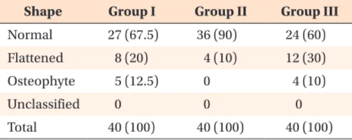
(7) Park et al • Condylar position and morphology. Table 6. Distribution of condylar shape in each group Shape. Group I. Group II. Group III. 27 (67.5). 36 (90). 24 (60). 8 (20). 4 (10). 12 (30). Osteophyte. 5 (12.5). 0. 4 (10). Unclassified. 0. 0. 0. Normal Flattened. Total. 40 (100). 40 (100). 40 (100). Values are presented as number (%). Group I, Hypodivergent; Group II, normodivergent; Group III, hyperdivergent.. Table 7. Condylar shape distribution within normal group Shape. Group I. Group II. Group III. Oval. 17 (63.0). 17 (47.2). 10 (41.7). Round. 10 (37.0). 19 (52.8). 14 (58.3). Values are presented as number (%). Group I, Hypodivergent; Group II, normodivergent; Group III, hyperdivergent.. CT.9,10,14,26,28 In the present study, an expert orthodontist measured all the variables by using CBCT software. The software simultaneously provides sagittal, axial, coronal, and 3D reconstructed views of every landmark; measurement errors caused by inaccurate determination of key anatomic points are therefore minimized.24 The study excluded patients with TMJ dysfunction or degenerative joint diseases who had received treat ment. Those without TMD history were included de pending on absence of TMD symptoms. Subject se lection may therefore be a limitation: the patients were not radiographically screened, so asymptomatic patients with degenerative joint diseases could have been included. Osteoarthritis, a degenerative change in joints is radiographically characterized by subcortical cysts, surface erosion, osteophytes, and/or generalized sclerosis. 29 In the present study, 9 condyles showed osteophytes (5 and 4 in the hypodivergent and hyper divergent groups, respectively). Further, 24 condyles were flattened, including 8, 4, and 12 condyles in the hypodivergent, normodivergent, and hyperdivergent groups, respectively. Because these patients did not pre sent symptoms such as pain, clicking, and limited mouth opening, they were not excluded. Notably, osteoarthritis cannot be diagnosed by CBCT alone. Additional diagnostic tools, such as magnetic resonance imaging and clinical examination, are required for accurate diagnosis and proper treatment. Patients requiring orthodontic treatment often have TMDs.27,30,31 Therefore, orthodontic treatment should. 72. be aimed at not only correcting tooth alignment and occlusal relationships but also normalizing condylar position. Consideration of condylar morphology and po sition as well as centric relation during treatment plan ning would yield better outcomes.. CONCLUSION Patients with the hyperdivergent skeletal pattern tend to have smaller and more superiorly positioned condyles than those with the hypodivergent skeletal pattern. They also have narrower angle between the midsagittal plane and the condylar axis. Therefore, condylar position and morphology vary according to vertical facial morphology. This relationship should be considered for predicting and treating TMDs during orthodontic treatment.. REFERENCES 1. Girardot RA Jr. Comparison of condylar position in hyperdivergent and hypodivergent facial skeletal types. Angle Orthod 2001;71:240-6. 2. Ponces MJ, Tavares JP, Lopes JD, Ferreira AP. Comparison of condylar displacement between three biotypological facial groups by using mounted models and a mandibular position indicator. Korean J Orthod 2014;44:312-9. 3. Vitral RW, Telles Cde S, Fraga MR, de Oliveira RS, Tanaka OM. Computed tomography evaluation of temporomandibular joint alterations in patients with class II division 1 subdivision malocclusions: con dyle-fossa relationship. Am J Orthod Dentofacial Orthop 2004;126:48-52. 4. Rodrigues AF, Fraga MR, Vitral RW. Computed tomography evaluation of the temporomandibular joint in Class I malocclusion patients: condylar sym metry and condyle-fossa relationship. Am J Orthod Dentofacial Orthop 2009;136:192-8. 5. Schudy FF. Treatment of adult midline deviation by condylar repositioning. J Clin Orthod 1996;30:343-7. 6. Matsumoto MA, Bolognese AM. Radiographic mor phology of the temporomandibular joint related to occlusal characteristics. Braz Dent J 1994;5:115-20. 7. Burley M. An examination of the relation bet ween the radiographic appearance of the temporo mandibular joint and some features of the occlu sion. Br Dent J 1961;110:195-200. 8. Custodio W, Gomes SG, Faot F, Garcia RC, Del Bel Cury AA. Occlusal force, electromyographic activity of masticatory muscles and mandibular flexure of subjects with different facial types. J Appl Oral Sci 2011;19:343-9. 9. Stringert HG, Worms FW. Variations in skeletal and dental patterns in patients with structural and func. http://dx.doi.org/10.4041/kjod.2015.45.2.66. www.e-kjo.org.
(8) Park et al • Condylar position and morphology. tional alterations of the temporomandibular joint: a preliminary report. Am J Orthod 1986;89:285-97. 10. Burke G, Major P, Glover K, Prasad N. Correlations between condylar characteristics and facial morpho logy in Class II preadolescent patients. Am J Orthod Dentofacial Orthop 1998;114:328-36. 11. Cohlmia JT, Ghosh J, Sinha PK, Nanda RS, Currier GF. Tomographic assessment of temporomandibular joints in patients with malocclusion. Angle Orthod 1996;66:27-35. 12. Gianelly AA, Petras JC, Boffa J. Condylar position and Class II deep-bite, no-overjet malocclusions. Am J Orthod Dentofacial Orthop 1989;96:428-32. 13. Naeije M, Te Veldhuis AH, Te Veldhuis EC, Visscher CM, Lobbezoo F. Disc displacement within the hu man temporomandibular joint: a systematic review of a ‘noisy annoyance'. J Oral Rehabil 2013;40:13958. 14. Dalili Z, Khaki N, Kia SJ, Salamat F. Assessing joint space and condylar position in the people with normal function of temporomandibular joint with cone-beam computed tomography. Dent Res J (Isfahan) 2012;9:607-12. 15. Tsiklakis K, Syriopoulos K, Stamatakis HC. Radio graphic examination of the temporomandibular joint using cone beam computed tomography. Den tomaxillofac Radiol 2004;33:196-201. 16. Hayashi T, Ito J, Koyama J, Hinoki A, Kobayashi F, Torikai Y, et al. Detectability of anterior displacement of the articular disk in the temporomandibular joint on helical computed tomography: the value of open mouth position. Oral Surg Oral Med Oral Pathol Oral Radiol Endod 1999;88:106-11. 17. Ikeda K, Kawamura A. Assessment of optimal con dylar position with limited cone-beam computed tomography. Am J Orthod Dentofacial Orthop 2009;135:495-501. 18. Seren E, Akan H, Toller MO, Akyar S. An evaluation of the condylar position of the temporomandibular joint by computerized tomography in Class III mal occlusions: a preliminary study. Am J Orthod Den tofacial Orthop 1994;105:483-8. 19. Vitral RW, Telles Cde S. Computed tomography evaluation of temporomandibular joint alterations in class II Division 1 subdivision patients: condylar symmetry. Am J Orthod Dentofacial Orthop 2002; 121:369-75. 20. Hilgers ML, Scarfe WC, Scheetz JP, Farman AG. Accuracy of linear temporomandibular joint mea surements with cone beam computed tomography and digital cephalometric radiography. Am J Orthod Dentofacial Orthop 2005;128:803-11.. www.e-kjo.org. http://dx.doi.org/10.4041/kjod.2015.45.2.66. 21. Saccucci M, Polimeni A, Festa F, Tecco S. Do skeletal cephalometric characteristics correlate with condylar volume, surface and shape? A 3D analysis. Head Face Med 2012;8:15. 22. Katsavrias EG. Morphology of the temporoman dibular joint in subjects with Class II Division 2 malocclusions. Am J Orthod Dentofacial Orthop 2006;129:470-8. 23. Rodrigues AF, Fraga MR, Vitral RW. Computed tomography evaluation of the temporomandibular joint in Class II Division 1 and Class III malocclusion patients: condylar symmetry and condyle-fossa relationship. Am J Orthod Dentofacial Orthop 2009;136:199-206. 24. Shahidi S, Vojdani M, Paknahad M. Correlation between articular eminence steepness measured with cone-beam computed tomography and clinical dysfunction index in patients with temporoman dibular joint dysfunction. Oral Surg Oral Med Oral Pathol Oral Radiol 2013;116:91-7. 25. Ahn SJ, Kim TW, Lee DY, Nahm DS. Evaluation of internal derangement of the temporomandibular joint by panoramic radiographs compared with ma gnetic resonance imaging. Am J Orthod Dentofacial Orthop 2006;129:479-85. 26. Zhang ZL, Cheng JG, Li G, Zhang JZ, Zhang ZY, Ma XC. Measurement accuracy of temporomandibular joint space in Promax 3-dimensional cone-beam computerized tomography images. Oral Surg Oral Med Oral Pathol Oral Radiol 2012;114:112-7. 27. Yang IH, Moon BS, Lee SP, Ahn SJ. Skeletal diffe rences in patients with temporomandibular joint disc displacement according to sagittal jaw relationship. J Oral Maxillofac Surg 2012;70:e349-60. 28. Ahmad M, Hollender L, Anderson Q, Kartha K, Ohr bach R, Truelove EL, et al. Research diagnostic cri teria for temporomandibular disorders (RDC/TMD): development of image analysis criteria and examiner reliability for image analysis. Oral Surg Oral Med Oral Pathol Oral Radiol Endod 2009;107:844-60. 29. Nah KS. Condylar bony changes in patients with temporomandibular disorders: a CBCT study. Ima ging Sci Dent 2012;42:249-53. 30. Ahn SJ, Baek SH, Kim TW, Nahm DS. Discrimination of internal derangement of temporomandibular joint by lateral cephalometric analysis. Am J Orthod Dentofacial Orthop 2006;130:331-9. 31. Katsavrias EG, Halazonetis DJ. Condyle and fossa shape in Class II and Class III skeletal patterns: a morphometric tomographic study. Am J Orthod Dentofacial Orthop 2005;128:337-46.. 73.
(9)
수치
+3
관련 문서
