Imaging Science in Dentistry 2015; 45: 73-80 http://dx.doi.org/10.5624/isd.2015.45.2.73
Introduction
Treatment of edentulous areas with dental implants is becoming a popular choice for patients and a reliable met
hod for dentists. Diagnostic evaluation and preoperative treatment planning of implant sites has undergone signifi
cant changes since the advent of conebeam computerized tomography(CBCT).1 Accurate dimensional evaluation of potential implant sites is the key to successful placement of implants during surgery. CBCT provides accurate lin
ear measurements and is comparable to physical measure
ments with a relative error of less than 1%.2 CBCT allows depiction of the area of interest in three dimensions and
in all the three orthogonal planes devoid of superimposi
tion of anatomical structures and provides highresolution images to make dimensional measurements.35 Pertl et al.6 compared the diagnostic accuracy of panoramic radiogra
phy with multidetector computed tomography(MDCT) and CBCT imaging for determining the alveolar dimen
sions. They measured the vertical height of the alveolar bone in relation to the mandibular canal on both imaging modalities and concluded that panoramic radiographs have a high range of distortion error that ranges between -0.2mm and 5.7mm and CBCT scan errors ranging from -1.5mm to 0.8mm.
Although CBCT offers high resolution and dimension
ally accurate images, obtaining accurate measurements of potential implant sites as measured by different observers and at different time points remains challenging. Studies have reported conflicting results regarding measurement accuracy in CBCT scans.610 Ganguly et al. studied radi
Evaluation of linear measurements of implant sites based on head orientation during acquisition: An ex vivo study using cone-beam computed tomography
Hanadi Sabban1, Mina Mahdian1, Ajay Dhingra2, Alan G. Lurie1, Aditya Tadinada1,*
1Section of Oral and Maxillofacial Radiology, Department of Oral Diagnostic Sciences, University of Connecticut School of Dental Medicine, Farmington, CT, USA
2Section of Prosthodontics, Department of Reconstructive Sciences, University of Connecticut School of Dental Medicine, Farmington, CT, USA
AbstrAct
Purpose: This study evaluated the effect of various head orientations during conebeam computed tomography (CBCT) image acquisition on linear measurements of potential implant sites.
Materials and Methods: Six dry human skulls with a total of 28 implant sites were evaluated for seven different head orientations. The scans were acquired using a Hitachi CBMercuRay CBCT machine. The scanned volumes were reconstructed. Horizontal and vertical measurements were made and were compared to measurements made after simulating the head position to corrected head angulations. Data was analyzed using a twoway ANOVA test.
results: Statistical analysis revealed a significant interaction between the mean errors in vertical measurements with a marked difference observed at the extension head position(P<0.05). Statistical analysis failed to yield any significant interaction between the mean errors in horizontal measurements at various head positions.
conclusion: Head orientation could significantly affect the vertical measurements in CBCT scans. The main head position influencing the measurements is extension.(Imaging Sci Dent 2015; 45: 73-80)
KEy words: ConeBeam Computed Tomography; Dental Implants; Patient Positioning; Dimensional Measurement Accuracy
Copyright ⓒ 2015 by Korean Academy of Oral and Maxillofacial Radiology
This is an Open Access article distributed under the terms of the Creative Commons Attribution NonCommercial License(http://creativecommons.org/licenses/bync/3.0) which permits unrestricted noncommercial use, distribution, and reproduction in any medium, provided the original work is properly cited.
Imaging Science in Dentistry·pISSN 22337822 eISSN 22337830 Received October 28, 2014; Revised January 16, 2015; Accepted February 12, 2015
*Correspondence to : Prof. Aditya Tadinada
Section of Oral and Maxillofacial Radiology, Department of Oral Diagnostic Sciences, University of Connecticut Health Center, 263 Farmington Ave., Farmington, CT 06030, USA
Tel) 18606792579, Fax) 18606794760, Email) [email protected]
*표 선 두께
=
1/0.3ptopaque fiduciary markers made of gutta percha placed over the buccal and lingual cortical plates of the mandi
bles in cadaver heads and compared them with physical measurements using calipers. They concluded that CBCT is reliable for linear measurement of preoperative im
plant sites with an error of less than 1mm.7 On the other hand, when Leung et al. studied the skull’s alveolar bone margins for evaluation of dehiscence and fenestration, they found that CBCT underestimated the bone margin by up to 6mm, and they attributed this to the decreased spatial resolution of CBCT in comparison to conventional periapical radiography.10 If CBCT was to be routinely used for implant treatment planning, a dimensional inaccuracy of 12mm would be critical in the final selection of the implant size and type and surgical management of the im
plant site and placement.
In a significant number of large volume CBCT scanners, there are no head positioning restraints or guides that help in standardization of the head position to compare or over
lay it with subsequent, comparable CBCT scans. Several studies of the measurement accuracy of CBCT scans have shown that it is critically important to perform quantitative analysis of the scans based on a corrected orientation of the area of interest in all the three orthogonal planes.1113 Inability to account for this discrepancy will result in un
der or overestimated measurements at the potential im
plant site leading to an erroneous estimation of the avail
able bone and can affect the final implant size and type selection. To the best of our knowledge, there has been limited information on measurement discrepancy associ
ated with changes in head orientation during scan acqui
sition. Thus, this study aimed to evaluate the effect of var
ious head positions and angulations on the accuracy of implant site measurements using CBCT scans. We also sought to evaluate the role of reconstruction software and its ability to adjust and correct the basic orthogonal ima
ging planes in all three axes(x, y, and z) to the standard position in correction of the existing measurement error.
Materials and Methods
Six dry human skulls were randomly selected from the University of Connecticut’s anatomy lab with no informa
tion about gender, age, or ethnicity of the skulls. The sel
ection of skulls was done on the basis of having missing anterior and posterior teeth with continuous and intact buccal, lingual, and palatal bone cortices. Due to the dif
ficulty involved in selecting skulls with specific areas of
missing teeth, clinical crowns were modified and or re
duced to the level of the alveolar crest using a highspeed fissure bur with a high cooling system to avoid damaging the surrounding alveolar bone. Our goal was to create two edentulous spaces(one anterior and one posterior) that would act as potential implant sites in each arch.
Method for the design of the platform
To be able to reproduce centric and eccentric skull/neck angulations resembling clinical situations, we designed a wooden platform with a screw in the center of the plat
form to seat the tripod stand’s base(Manfrotto 804RC2;
Cassola VI, Italy), upon which the skulls were fixed. The tripod stand had calibrated angles in the x, y, and z direc
tions that help in tilting and adjusting the wooden platform, in order to simulate the desired angle akin to a clinical situation. This arrangement enabled creation of various skull positions by dialing the desired angle on the tripod’s base while imaging the skulls in various simulated head positions with defined/standardized angles.
To reproduce the location of the skull position on the wooden platform, three radiographic points were used.
These points helped in localizing the skulls over the woo
den platform. Three gutta percha points(size 15) were placed on the mandible; one in the center, one on the right angle, and one on the left angle of the mandible. Parallel lines were marked on the wooden platform to align with the marked point. A soft pad was placed under the base of the skull in the occipital region to establish parallelism of the skull to simulate a normal occlusal plane, and the skull was fixed in place using clear tape. Each skull was given a random number from 1 to 6 prior to imaging.
After the skull was seated on the wooden platform with
in the desired position, the platform was fixed to the tripod.
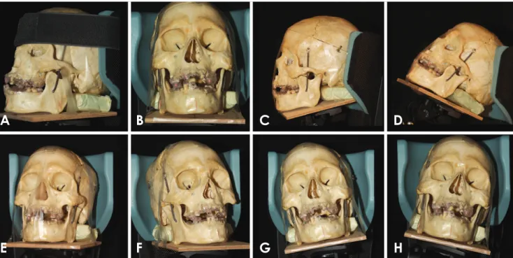
Seven CBCT scans were acquired for each skull in seven different positions using a Hitachi CB MercuRay CBCT machine(Hitachi Medical Systems, Kyoto, Japan) with a 6inch FOV(Fig. 1). The scans were done with exposure parameters of 120kVp, 15mA, and an acquisition time of 10 seconds.
Measurement protocol
In this pilot study, measurements were done by an Oral and Maxillofacial Radiology resident(HS) under the sup
ervision of an experienced Oral and Maxillofacial radiol
ogist(AT). All the acquired CBCT scan data were stored in the DICOM3(Digital Imaging and Communication
in Medicine) format and were viewed using InVivo Den
tal CBCT reconstruction software(Anatomage Inc., San Jose, CA, USA). A split screen dual monitor CBCT re
construction workstation was used for analysis(HP Com
paq DC7800, HP Corp., Palo Alto, CA, USA).
Each scan had six implant sites, which were marked by the radiographic stents placed on the teeth and the edentu
lous spaces prior to imaging. A simulated panoramic rec
onstruction was done for all the scans by drawing a curve along the center of the ridge in the axial plane, and cross sectional images of the sites of interest were generated with a slice thickness of 0.5mm and pitch distance of 1 mm. To minimize error in measurements, the reconstruc
tions were done in an identical manner for all the scans.
Based on the location of the radiographic guides, the pot
ential implant sites were identified and displayed as single crosssectional images on the screen. Evaluation of the site was subsequently performed based on the measure
ments done at the center of the edentulous site with the radiographic marker located in the center of the cross sec
tional image(Fig. 2).
A vertical and a horizontal measurement of the alveolar bone were done for each site. The vertical measurement
was defined as the height of the alveolar ridge from the crest to the floor of the maxillary sinus or nasal fossa in the maxilla and the inferior border of the mandible or the superior cortex of the mandibular canal in the mandibular arch. Horizontal measurement was defined as the bucco
lingual width of the alveolar ridge measured halfway along the vertical axis. The measurements of the seven different head orientations of the same implant site were compared.
For the second part of the study, correction of the head position was done by rectifying the acquired scan volume in the X, Y, and Z axes. The Zaxis is most valuable in the correction of the accentuated neck position most common
ly encountered in clinical situations. We took Frankfort’s horizontal plane to be the desired head position that yields accurate implant site measurements. The aim of this part of the study was to compare the corrected head position with the accentuated head position at acquisition and see the percentage of error that was mitigated.
We performed software correction of three head posi
tions to examine the percentage of software correction of the error factor. This was evaluated after measuring the same six proposed implant sites of all the six cases. These
Fig. 1. Various head positions. A and B. Centric: The three tripod angles marked at zero degrees; it demonstrates zero x, y, and z axes. The occlusal plane and the Frankfort’s horizontal plane is parallel to the floor. This position is considered to be the gold standard position. C.
Flexion: The skull is tilted downward anteriorly by 20 degrees. D. Extension: The skull is tilted upward and backward by 20 degrees. E.
Right flexion: The skull is moved 20 degrees laterally, away from the midline towards the right side. F. Left flexion: The skull is moved 20 degrees laterally, away from the midline towards the left side. G. Right lateral: The skull is directed 15 degrees towards the right shoulder. H.
Left lateral: The skull is directed 15 degrees towards the left shoulder.
A B C D
E F G H
three positions were flexion, extension, and right flexion, which were selected randomly.
Statistical analyses were performed using SAS software.
Comparison of each head position with the gold standard (centric) was done using twoway ANOVA. The mean of error interaction for each vertical and horizontal measure
ment was analyzed. P values less than 0.05 were deemed significant.
results
The data analyzed for this study included 6 dry skulls with 28 sites(12 anterior teeth and 16 molars). Errors in measurements of the potential implant sites were com
pared among the 6 different head positions. The measure
ments were performed with the centric head position as the gold standard. ANOVA was used to test the effects of the various head positions and their interactions.
Tables 1 and 2 show the mean and standard deviations of errors for vertical and horizontal measurements, respec
tively, for each head position and each area. The ANOVA test results revealed a statistically significant interaction between the mean errors in vertical measurements(P<
0.05). According to Tukey’s test, the marked difference between the mean errors was observed at the extension head position(P<0.05). The statistical analysis failed to yield any significant interaction between the mean errors in the horizontal measurements at various head positions.
Figure 3 shows the interactions between the mean er
rors of horizontal and vertical measurements at various head positions in different implant sites. The dots in the plot represent the means of errors for each head position and each area. A significant interaction is observed bet
ween the mean errors in the vertical measurements.
The results of this part of the study showed that all the six cases had a significantly different measurement when
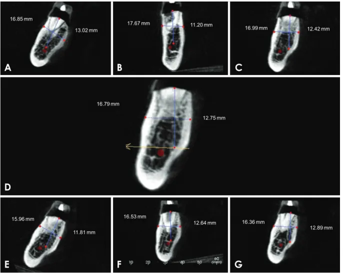
Fig. 2. Vertical and horizontal measurements of the alveolar ridge at a molar site at various head positions. A. Extension, B. Flexion, C.
Right, D. Centric, E. Left, F. Right flexion, G. Left flexion.
A B C
D
E F G
16.85mm
13.02mm 17.67mm
16.79mm
15.96mm
11.81mm
16.53mm
12.64mm 16.36mm
12.89mm 11.20mm
12.75mm
16.99mm 12.42mm
the sites were measured at eccentric angles and compared to the centric head position acquired with the Frankfort’s horizontal plane parallel to the floor of the acquisition room, which we marked as the zero angle. When we did software correction of the eccentric head position and mea
sured the implant sites again, the software correction show
ed that the implant sites were measured as having very
similar dimensions to those measured with the centric head position(Table 3).
discussion
In this study we evaluated the linear measurement error at the upper and lower anterior and posterior implant sites
Table 1. Mean and standard deviations of errors for vertical measurements at all implant sites(excluding the premolars) in various head positions(mm)
Area Extension* Flexion Left lateral Left flexion Right lateral Right flexion
Lower anterior 0.43±4.21* -0.28±0.77 -1.41±4.25 1.43±1.77 -0.82±0.53 0.70±1.77
Lower posterior -2.02±5.12* 2.04±2.68 1.29±4.32 -0.93±0.98 -0.19±0.56 -0.40±0.68
Upper anterior 1.02±2.71* -0.62±1.05 -0.23±1.83 0.46±1.91 -0.18±1.37 1.23±2.40
Upper posterior 3.30±3.21* -0.84±4.71 0.05±0.78 0.20±0.56 -0.14±1.64 0.50±1.46
*P<0.05
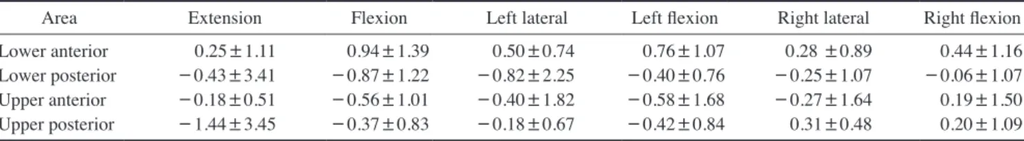
Table 2. Mean and standard deviations of errors for horizontal measurements at all implant sites(excluding the premolars) in various head positions(mm)
Area Extension Flexion Left lateral Left flexion Right lateral Right flexion
Lower anterior 0.25±1.11 0.94±1.39 0.50±0.74 0.76±1.07 0.28 ±0.89 0.44±1.16
Lower posterior -0.43±3.41 -0.87±1.22 -0.82±2.25 -0.40±0.76 -0.25±1.07 -0.06±1.07
Upper anterior -0.18±0.51 -0.56±1.01 -0.40±1.82 -0.58±1.68 -0.27±1.64 0.19±1.50
Upper posterior -1.44±3.45 -0.37±0.83 -0.18±0.67 -0.42±0.84 0.31±0.48 0.20±1.09
Fig. 3. Mean error of vertical and hor
izontal measurements for each head position at different implant sites.
Mean of Error(Horizontal vs Vertical) VorH=Horizontal VorH=Vertical
Headpos
Error: difference between the measurement taken at other position and measurements taken at zero angle Area
Lower anterior Lower posterior Upper anterior Upper posterior
Extension Flexion Left Flexion Left
Left_flex Right Left_flex Right
Right_flexExtension Right_flex
The mean, Error
2
0
-2
in various eccentric head positions during CBCT exam
ination. The majority of conebeam machines’ manuals suggest seating the patient based on reference lines in a way that the occlusal plane is parallel to the floor and the patient’s head is in a relaxed position to minimize move
ment.
Patients with skeletal malformation or malocclusion, who are mostly referred for orthodontic treatment planning or surgical procedures, are at a higher risk of possible mea
surement discrepancies due to the maxillamandible rela
tionship.
Potential dental implant sites are often assessed using CBCT scans to determine the size and type of implant and also to decide on the need for bone augmentation or sinus /site augmentation based on the measurements yielded by CBCT. In this regard, having accurate and reliable mea
surements becomes very important for final implant sel
ection.
Araki et al.14 found that the linear accuracy of measure
ments done on CBCT machines with image intensifiers was adequate to translate into the clinical setting. This concept was further shown to be true with a study done by Statemann et al.,15 who compared the CB MercuRay and NewTom CBCT machines with physical measurements and found them to be reliably similar. Based on the results of these studies, we decided to compare only CBCTderi
ved measurements. This is one of the limitations of the study, in that our institutional rules did not permit cutting and analyzing dry skulls to derive physical measurements.
However, we felt that the existing literature adequately supports that CBCT measurements are reliably similar to physical measurements. To address some of the clinical
challenges that have been under discussion, this study eva
luated the effect of various head positions and orientations during CBCT scans at anterior and posterior implant sites for both upper and lower jaws.
Moreira et al.16 and Frongia et al.17 failed to show a significant measurement discrepancy in CBCT volumes among patients referred for orthodontic treatment planning.
This was possibly because they ignored discrepancies of a small number of millimeters, whereas for implant treat
ment planning, every tenth of a millimeter is significant and any measurement discrepancy could affect the suc
cess rate of the implant. Wrong estimation of an implant site may cause irreversible damage to vital anatomical structures such as the inferior alveolar nerve, vascular structures, maxillary sinus, or nasal cavity.
In another study by Sheikhi et al., a measurement error of only 0.5mm was observed because they used small angles(1015mm) and only four selected head orienta
tions.18 In a recent study by Visconti et al.,19 they studied the effect of the position of the gnathic bones on bone heights and widths for potential implant sites. They scan
ned ten dry edentulous human skulls using an ICAT cone
beam machine and standardized the field of view to 6cm for skulls in standard positions and 10cm for skulls with other inclinations. The scan was done in four different orientations, each orientation with two angles, 10 and 20.
They demonstrated a significant influence of the head position on measurement reliability, and the greatest dis
crepancy was observed in the upper and lower premolar areas.
In the present study, we used the 6inch field of view for all our scans and attempted to simulate clinical conditions
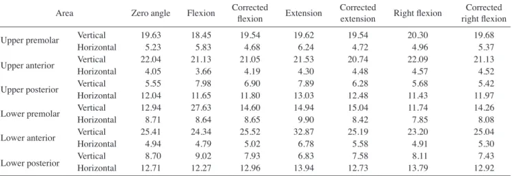
Table 3. Mean horizontal and vertical measurements for six implant sites in three selective head positions and their respective corrected positions(mm)
Area Zero angle Flexion Corrected
flexion Extension Corrected
extension Right flexion Corrected right flexion
Upper premolar Vertical 19.63 18.45 19.54 19.62 19.54 20.30 19.68
Horizontal 5.23 5.83 4.68 6.24 4.72 4.96 5.37
Upper anterior Vertical 22.04 21.13 21.05 21.53 20.74 22.09 21.13
Horizontal 4.05 3.66 4.19 4.30 4.48 4.57 4.52
Upper posterior Vertical 5.55 7.98 6.90 7.89 6.28 5.68 5.42
Horizontal 12.04 11.65 11.80 13.03 12.48 11.43 11.97
Lower premolar Vertical 12.94 27.63 14.60 14.94 15.04 11.74 14.26
Horizontal 8.71 8.64 8.65 9.90 8.42 7.85 8.08
Lower anterior Vertical 25.41 24.34 25.52 32.87 25.19 23.20 25.04
Horizontal 4.94 4.79 5.02 6.78 5.58 4.91 5.30
Lower posterior Vertical 8.70 9.02 7.93 6.83 7.58 8.11 7.43
Horizontal 12.71 12.27 12.96 13.94 12.73 13.79 12.92
by creating implant sites in dentate jaws. We did the scans in six different orientations in addition to the standard pos
ition and studied more than one lateral movement. Simul
taneously, we attempted to evaluate the effect of combined movement in the form of lateral flexion position on the measurement accuracy.
The mean error and standard deviation for vertical and horizontal measurements was calculated for all implant sites. The premolar sites were excluded from analysis due to close proximity with the mental foramen and the nerve loop, which resulted in a wide range of vertical measure
ments. The statistical analysis of vertical measurements showed mean errors ranging between -2mm and 3mm in various head positions, mainly seen in the extension posi
tion and in the posterior areas.
The range of discrepancy in horizontal measurements was less than 1mm at most sites in various head positions except for that of the upper posterior site in the extension position, which was deemed insignificant. One possible explanation would be that since vertical measurements are generally greater than horizontal measurements, in eccen
tric positions, the dimension that is more severely affect
ed is the vertical dimension. Furthermore, the volume of bone that is displaced in the image layer in an eccentric position is greater along the vertical axis.
The second part of the present study described the per
centage of software correction using the tools in the InVivo software program. The correction percentages in vertical and horizontal measurements in the flexion and extension positions ranged between 8388%. This percentage in the vertical measurement in right flexion position was 75%.
It is important to note that that in our study, we only cor
rected three head positions, and we did not differentiate between site locations in the jaws. That means that soft
ware can correct the measurement error by close to 90% in most cases. Our results indicated that the software does not have the ability to completely correct the measure
ment error to normal; however, in the majority of cases, the correction is close to normal.
The limitation of this pilot study is that observer reli
ability was not performed due to the large number of mea
surements that were recorded; therefore, we feel further studies with inter and intraobserver reliability should be performed. Furthermore, there were certain areas in which correction was not optimally achieved, which may have been due to a discrepancy in more than one axis of the head orientation, panoramic and crosssectional re
construction that was sensitive to software manipulation,
and inter and intraexaminer variability.
In conclusion, head orientation and position can signifi
cantly affect the vertical and horizontal measurements in CBCT scans. The two main head positions influencing the measurements are extension and flexion. The measure
ment discrepancy is more frequently seen in the posterior mandibular region. It is recommended that in the lack of appropriate head position during scan acquisition, correc
tion of the Z axis parallel to the Frankfort’s horizontal plane may minimize the measurement error.
references
1. Benavides E, Rios HF, Ganz SD, An CH, Resnik R, Reardon GT, et al. Use of cone beam computed tomography in implant dentistry: the International Congress of Oral Implantologists consensus report. Implant Dent 2012; 21: 7886.
2. Das KP, Jahangiri L, Katz RV. The first-choice standard of care for an edentulous mandible: a Delphi method survey of aca
demic prosthodontists in the United States. J Am Dent Assoc 2012; 143: 8819.
3. Yim JH, Ryu DM, Lee BS, Kwon YD. Analysis of digitalized panorama and cone beam computed tomographic image dis
tortion for the diagnosis of dental implant surgery. J Craniofac Surg 2011; 22: 66973.
4. ElBeialy AR, Fayed MS, ElBialy AM, Mostafa YA. Accu
racy and reliability of conebeam computed tomography mea
surements: influence of head orientation. Am J Orthod Dento- facial Orthop 2011; 140: 15765.
5. Raes F, Renckens L, Aps J, Cosyn J, De Bruyn H. Reliability of circumferential bone level assessment around single im
plants in healed ridges and extraction sockets using cone beam CT. Clin Implant Dent Relat Res 2013; 15: 66172.
6. Pertl L, GashiCenkoglu B, Reichmann J, Jakse N, Pertl C.
Preoperative assessment of the mandibular canal in implant surgery: comparison of rotational panoramic radiography (OPG), computed tomography(CT) and cone beam computed tomography(CBCT) for preoperative assessment in implant surgery. Eur J Oral Implantol 2013; 6: 7380.
7. Ganguly R, Ruprecht A, Vincent S, Hellstein J, Timmons S, Qian F. Accuracy of linear measurement in the Galileos cone beam computed tomography under simulated clinical condi
tions. Dentomaxillofac Radiol 2011; 40: 299305.
8. Tsutsumi K, Chikui T, Okamura K, Yoshiura K. Accuracy of linear measurement and the measurement limits of thin objects with cone beam computed tomography: effects of measure
ment directions and of phantom locations in the fields of view.
Int J Oral Maxillofac Implants 2011; 26: 91100.
9. Tarazona B, Llamas JM, Cibrian R, Gandia JL, Paredes V. A comparison between dental measurements taken from CBCT models and those taken from a digital method. Eur J Orthod 2013; 35: 16.
10. Leung CC, Palomo L, Griffith R, Hans MG. Accuracy and reliability of conebeam computed tomography for measuring
alveolar bone height and detecting bony dehiscences and fen
estrations. Am J Orthod Dentofacial Orthop 2010; 137: S109
11. Swennen GR, Schutyser F. Threedimensional cephalometry: 19.
spiral multislice vs conebeam computed tomography. Am J Orthod Dentofacial Orthop 2006; 130: 4106.
12. Loubele M, Maes F, Schutyser F, Marchal G, Jacobs R, Suet
ens P. Assessment of bone segmentation quality of conebeam CT versus multislice spiral CT: a pilot study. Oral Surg Oral Med Oral Pathol Oral Radiol Endod 2006; 102: 22534.
13. Hassan B, van der Stelt P, Sanderink G. Accuracy of threedi
mensional measurements obtained from cone beam computed tomography surfacerendered images for cephalometric analy
sis: influence of patient scanning position. Eur J Orthod 2009;
31: 12934.
14. Araki K, Maki K, Seki K, Sakamaki K, Harata Y, Sakaino R, et al. Characteristics of a newly developed dentomaxillofacial Xray cone beam CT scanner(CB MercuRay): system config
uration and physical properties. Dentomaxillofac Radiol 2004;
33: 519.
15. Stratemann SA, Huang JC, Maki K, Miller AJ, Hatcher DC.
Comparison of cone beam computed tomography imaging with physical measures. Dentomaxillofac Radiol 2008; 37:
8093.
16. Moreira CR, Sales MA, Lopes PM, Cavalcanti MG. Assess
ment of linear and angular measurements on threedimension
al conebeam computed tomographic images. Oral Surg Oral Med Oral Pathol Oral Radiol Endod 2009; 108: 4306.
17. Frongia G, Piancino MG, Bracco P. Conebeam computed to
mography: accuracy of threedimensional cephalometry anal
ysis and influence of patient scanning position. J Craniofac Surg 2012; 23: 103843.
18. Sheikhi M, Ghorbanizadeh S, Abdinian M, Goroohi H, Badri
an H. Accuracy of linear measurements of galileos cone beam computed tomography in normal and different head positions.
Int J Dent 2012; 2012: 214954.
19. Visconti MA, Verner FS, Assis NM, Devito KL. Influence of maxillomandibular positioning in cone beam computed tomography for implant planning. Int J Oral Maxillofac Surg 2013; 42: 8806.