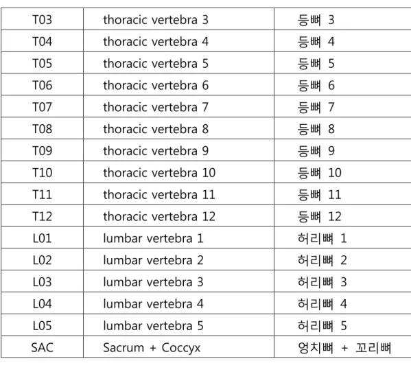
T03 thoracic vertebra 3 등뼈 3 T04 thoracic vertebra 4 등뼈 4 T05 thoracic vertebra 5 등뼈 5 T06 thoracic vertebra 6 등뼈 6 T07 thoracic vertebra 7 등뼈 7 T08 thoracic vertebra 8 등뼈 8 T09 thoracic vertebra 9 등뼈 9 T10 thoracic vertebra 10 등뼈 10 T11 thoracic vertebra 11 등뼈 11 T12 thoracic vertebra 12 등뼈 12 L01 lumbar vertebra 1 허리뼈 1 L02 lumbar vertebra 2 허리뼈 2 L03 lumbar vertebra 3 허리뼈 3 L04 lumbar vertebra 4 허리뼈 4 L05 lumbar vertebra 5 허리뼈 5
SAC Sacrum + Coccyx 엉치뼈 + 꼬리뼈
1.4 구축대상 표본목록 양식
표 1-3 구축대상 표본목록 양식
ID SEX AGE STATURE WEIGHT C_BMD COD file_name_prefix
인체 척추 영상/물성 정보 제작 방법
COD : 사망원인, 필요에 따라 사망진단서를 첨부할 수 있다
영상의학정보를 판독한 Radiologic finding(reading) 파일을 추가할 수 있다
인체 척추 영상/물성 정보 제작 방법
2.2.1 영상구역화 과정
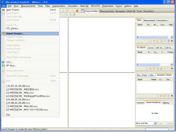
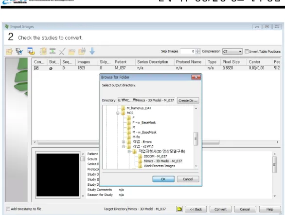
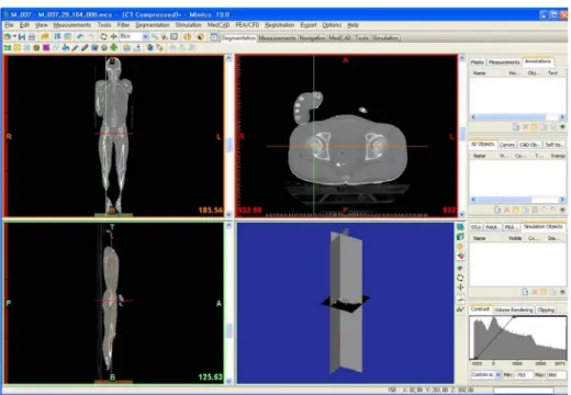
2.2.1.1 Data Set(DICOM Image Set) 생성
Mimics S/W 에서 DICOM 이미지를 오픈(혹은 입력)하여 Mimics Project File(.mcs)을 생성하고 3 차원 모델을 생성하기 위한 첫 번째 과정이다.
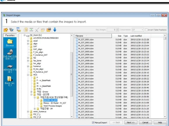
“Import Images”를 선택하여 DICOM Image Set 을 Import 한다.
그림 2-2 DICOM Data Set 선택
인체 척추 영상/물성 정보 제작 방법
그림 2-4 작업파일 저장 폴더 지정
인체 척추 영상/물성 정보 제작 방법
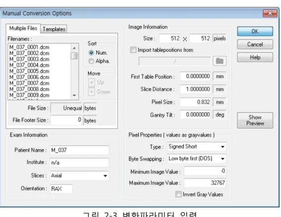
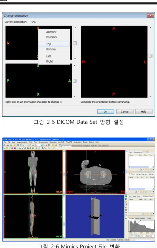
그림 2-5 DICOM Data Set 방향 설정
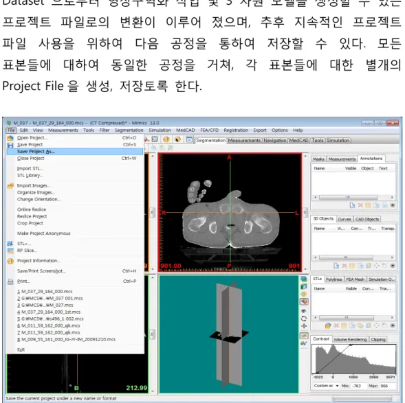
이와 같은 공정을 거쳐 가장 기본 입력 데이터인 DICOM Image Dataset 으로부터 영상구역화 작업 및 3 차원 모델을 생성할 수 있는 프로젝트 파일로의 변환이 이루어 졌으며, 추후 지속적인 프로젝트 파일 사용을 위하여 다음 공정을 통하여 저장할 수 있다. 모든 표본들에 대하여 동일한 공정을 거쳐, 각 표본들에 대한 별개의 Project File 을 생성, 저장토록 한다.
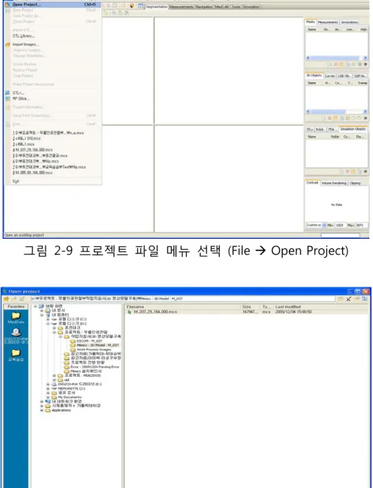
그림 2-9 프로젝트 파일 메뉴 선택 (File Open Project)
인체 척추 영상/물성 정보 제작 방법
그림 2-11 프로젝트 파일 Open
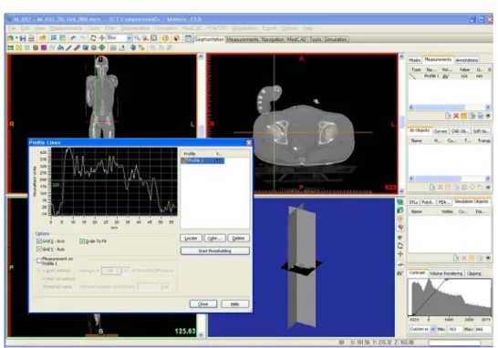
그림 2-13 선택 영역에 대한 Profile Line
인체 척추 영상/물성 정보 제작 방법
그림 2-15 기본 마스크 생성
이렇게 생성한 기본 마스크는 표본의 목뼈, 등뼈, 허리뼈, 엉치뼈, 꼬리뼈 모두를 포함하고 있는 마스크로써, 컴포넌트에 해당하는 각 뼈별로 별도의 마스크를 생성(ROI 별 Bone Mask)하여 영상구역화 작업을 실행토록 한다.
2.2.1.3 개별 척추뼈의 Base Mask 생성
인체 척추 영상/물성 정보 제작 방법
2.3 개별 척추뼈 3 차원 모델과 영상정보의 연관성 부여
앞 과정에서 제작되어 해당 뼈 이름으로 저장된 3 차원 모델파일과 CT 영상파일의 상호 연관성을 부여하기 위해 해당뼈 부분이 나타난 일렬인 CT 영상파일의 시작번호와 끝번호를 기록한다. 저장된 3 차원 모델의 활용을 위해 뼈 부피와 표면적 정보를 동시에 기록한다. 표 2-1 3 차원 모델 및 영상정보 입력 양식SampleID Bone Format StartNum EndNum Volume Surface HU_AVG HU_SD ESP_001 C01
L04 L05 SAC
그림 3-2 목뼈 1 번 자른면 보기 표 3-1 목뼈 1 번 측정 변수
측정변수 측정내용 비고
TPW Transverse process width
그림 3-1 SCD Maximal spinal canal depth
SCW Maximal spinal canal width mSCW Minimal spinal canal width
VAW Arch width at groove for vertebral artery (long Axis)
VAH Arch height at groove for vertebral artery
TFD Transverse foreman diameter 그림
3-2 LMW Lateral mass width
표 3-2 목뼈 2 번 측정 변수
측정변수 측정내용 비고
LTW Laminar width (perpendicular to long axis)
그림 3-3 LTH Laminar height (long axis)
SCD Maximal spinal canal depth SCW Maximal spinal canal width LL laminar screw length
PL1l Articulating process at maximal AP dimension
PL2l AP length of laminar at maximal AP dimension of articulating process
LA Laminar screw angle OD Odontoid process depth BD Vertebral body depth TPW Transverse process width
그림 3-4
OW Dens width
인체 척추 영상/물성 정보 제작 방법
(다) 목뼈 3-7 번 치수 측정
그림 3-5 목뼈 3-7 번 앞쪽 보기
그림 3-7 목뼈 3-7 번 위쪽 보기 2
인체 척추 영상/물성 정보 제작 방법
표 3-3 목뼈 3-7 번 측정 변수
측정변수 측정내용 비고
TPW Transverse process width 그림
3-5 EPWl Outter maximum width of lower endplate
SCD Maximal spinal canal depth
그림 3-6 SCW Maximal spinal canal width
PL1l Pedicle length within vertebral body in pedicle screw trajectory
PL2l Pedicle lenght out of vertebral body in pedicle screw trajectoy
PDAsl Pedicle screw insertion angle
PDWl,r Pedicle width (perpendicular to long axis)(left,right)
PDHl,r Pedicle height (long axis) (left,right)
EPWuM Maximal uncinate process width with outer cortex
그림 3-7 EPWuA Anterior uncinate process width with inner
cortex
EPWuC Maximal uncinate process width with inner cortex
EPWuP Posterior uncinate process width with inner cortex
EPDu Upper endplate depth
그림 3-8 EPDl Lower endplate depth
VBHa Anterior vertebral body height
SPL Spinous process length from center of upper endplate
ADH Anterior disk height
그림 3-17 CDH Center disk height
인체 척추 영상/물성 정보 제작 방법
표 3-4 등뼈 1-12 번 측정 변수
측정변수 측정내용 비고
TPW Transverse process width
그림 3-9 EPWuM Maximal upper endplate width
EPWl Maximal lower endplate width SCD Maximal spinal canal depth
그림 3-10 SCW Maximal spinal canal width
PL1l Pedicle length within vertebral body in pedicle screw trajectory
PL2l Pedicle lenght out of vertebral body in pedicle screw trajectoy
PDAsl Pedicle screw insertion angle
PDWl,r Pedicle width (perpendicular to long axis)
(left,right)
PDHl,r Pedicle height (long axis) (left,right) EPDu Upper endplate Depth
그림 3-11 EPDl Lower endplate Depth
VBHp Posterior vertebral body height VBHa Anterior vertebral body height SPL Spinous process length
PDlt Pedicle angle in sagittal plane ADH Anterior disk height
그림 3-18 CDH Center disk height
(마) 허리뼈 1-5 번 치수 측정
TPW
EPWuM
EPWl
표 3-5 허리뼈 1-5 번 측정 변수
측정변수 측정내용 비고
TPW Transverse process width
그림 3-12 EPWuM Maximal upper endplate width
EPWl Maximal lower endplate width SCD Maximal spinal canal depth
그림 3-13 SCW Maximal spinal canal width
PL1l Pedicle length within vertebral body in pedicle screw trajectory
PL2l Pedicle lenght out of vertebral body in pedicle screw trajectoy
PDAsl Pedicle screw insertion angle
PDWl,r Pedicle width (perpendicular to long axis)
(left,right)
PDHl,r Pedicle height (long axis) (left,right) EPDu Upper endplate depth
그림 3-14 EPDl Lower endplate depth
VBHp Posterior vertebral body height SPL Spinous process length
PDlt Pedicle angle in sagittal plane ADH Anterior disk height
그림 3-18 CDH Center disk height
인체 척추 영상/물성 정보 제작 방법
3.3 디스크 높이 측정
(가) 측정을 위한 절단 디스크 높이 측정을 위해 정중단면에서 절단하여 sagittal plane 에서 디스크 높이를 측정하고(그림 3-15), body center 중심으로 coronal plane 절단하여 해당 평면에서 디스크 높이를 측정(그림 3-16)한다. sagittal plane 에서의 측정은 목뼈, 등뼈, 허리뼈 모든 영역에서 해당되며, coronal plane 에서의 측정은 등뼈와 허리뼈에 해당된다. 디스크 높이의 언급은 해당 척추뼈 이름을 명칭할 때 아래 부분의 높이로 한다. (예 : T3 디스크 높이는 T3-T4 사이 디스크의 높이)그림 3-16 coronal plane cutting (나) 목뼈 디스크 높이 측정
목뼈 디스크 높이 측정은 sagittal plane 에서 vertebral body 의 앞, 중간, 끝 부분의 코너점을 기준으로 높이를 측정한다.
AD
H CD PDH
H
인체 척추 영상/물성 정보 제작 방법
(다) 등뼈 / 허리뼈 디스크 높이 측정
4. 골밀도 계산
4.1 목적
겉질뼈와 해면뼈로 구성된 척추체 부분의 골밀도를 계산하는 부분으로 척추체에 인접한 pedicle 에서 절단하여 척추 후궁 부위를 제외한 순수 몸체 부분의 골밀도를 계산한다. 골밀도 계산은 CT 촬영 영상의 음영값인 Hu 값을 기준으로 하며 계산식은 아래 값을 참고한다([1][2]).[kg/m
3]
4.2 Hu 값 계산
척추뼈의 몸체 부분의 Hu 값을 계산하기 위해인체 척추 영상/물성 정보 제작 방법
척추뼈고리뿌리 부분을 절단하여 남은 척추몸통 부분의 새로운 마스크를 생성한다.
인체 척추 영상/물성 정보 제작 방법
5. 척추 분절 기능성 시험
5.1 목적
목뼈 7 개, 등뼈 12 개, 허리뼈 5 개로 구성된 각각 척추 관절의 운동 특성을 생체역학적으로 시험하여 결과를 구축하는 공정으로 척추 2 개단이 연결된 1 개 분절(척추사이 원판과 주요 인대를 포함한다)에서의 폄 / 앞쪽굽힘 / 가쪽굽힘 / 비틀림 하중에 대한 각 분절의 운동 특성을 시험한다.5.2 시험체 준비
5.2.1 시험체 적출 시험에 사용될 척추 적출은 뼈 및 주요 인대가 손상되지 않게 주의해야 한다. 첫째목뼈(C1)에서 엉치뼈(sacrum) 까지 척추를 한번에 적출한다. 윗쪽으로는 바깥뒤통수뼈융기(external occipital protuberance) 부분을 절단하고, 가쪽으로는 척추 가로돌기(transcerse process) 가쪽 1cm 이상 떨어진 곳의 갈비뼈(rib)를 절단한다. 아래쪽으로는 엉치뼈의 첫번째단(S1) 아래 부분을 절단한다. 단 엉치뼈는 가쪽 부분 절단시 양쪽 날개(ala of sacrum) 부분이 절단될 수 있으나 시험에 영향을 미치지 않는다. 적출한 척추에서 주요 인대를 제외한 불필요한 연조직(soft tissue) 부분을 최대한 제거한다. 보존해야 하는 주요 구조물은인체 척추 영상/물성 정보 제작 방법
관절주머니(joint capsule) 앞세로인대(anterior longitudinal ligament), 뒤세로인대(posterior longitudinal ligament), 황색인대 (ligamentum
flavum), 가시사이인대(interspinous ligament),
가시끝인대(supraspinous ligament)이며, 등뼈의 경우 척추 관절주머니 내 구조물을 보존하기 위해 머리관절(joint of head of rib) 부분의 구조물을 추가로 보존한다. 단 갈비뼈와 가로돌기가 연결된 구조물들은 제거한다.
5.2.2 골밀도(BMD) 검사
시험에 사용할 척추의 골밀도 정도를 파악하기 위해 골밀도 검사를 실시한다. 골밀도 검사는 임상에서 실시하고 있는 허리뼈 부분의 이중에너지 X 선 흡수법 (DEXA, Dual Energy X-ray Absorption)을 적용한다. 측정된 각 허리뼈의 골밀도(T score)는 시험된 척추의 골밀도 정도를 파악하기 위해 시험 결과와 함께 제공한다.
인체 척추 영상/물성 정보 제작 방법
Vertebral Disk Compression
7. 참고 문헌
[1] McBroom, R.J., Hayes, W.C., Edwards, W.T., Goldberg, R.P., White, A.A. “Prediction of Vertebral Body Compressive Fracture using Quantitative Computed Tomography” Journal of Bone and Joint Surgery, Vol. 67-A, No. 8 (1985) 1206-1214
[2] Rho, J.Y., Hobatho, M.C., and Ashman, R.B. “Relations of Mechanical Properties to Density and CT Numbers in Human Bone” Medical Engineering and Physics, Vol. 17, No. 5 (1995) 347-355
[3] Mechanical properties of the human cervical spine as shown by three-dimensional load-displacement curves, Spine. 2001 Dec 15;26(24):2692-2700.
[4] Mechanical properties of the human thoracic spine as shown by three-dimensional load-displacement curve , J Bone Joint Surg Am. 1976 Jul;58(5):642-52.
[5] Three-dimensional movements of the whole lumbar spine and