• 검색 결과가 없습니다.

A Study on the Uniformity Improvement of Residual Layer of a Large Area Nanoimprint Lithography

N/A
N/A
Protected

Academic year: 2021

Share "A Study on the Uniformity Improvement of Residual Layer of a Large Area Nanoimprint Lithography"

Copied!
5
0
0

로드 중.... (전체 텍스트 보기)

전체 글

(1)

A Study on the Uniformity Improvement of Residual Layer of a Large Area Nanoimprint Lithography

Kug Weon Kim

, Rafigul I. Noorani* and Nam Woong Kim**

Dept. of Mechanical Engineering, Soonchunhyang University, Asan 336-745, Korea

*Dept. of Mechanical Engineering, Loyola Marymount University. LA, CA 90045, USA

**School of Mechanical Engineering, Dongyang Mirae University, Seoul 152-714, Korea

ABSTRACT

Nanoimprint lithography (NIL) is one of the most versatile and promising technology for micro/nano-patterning due to its simplicity, high throughput and low cost. Recently, one of the major trends of NIL is large-area patterning. Especially, the research of the application of NIL to TFT-LCD field has been increasing. Technical difficulties to keep the uniformity of the residual layer, however, become severer as the imprinting area increases. In this paper we performed a numerical study for a large area NIL (the 2

nd

generation TFT-LCD glass substrate (370×470 mm)) by using finite element method.

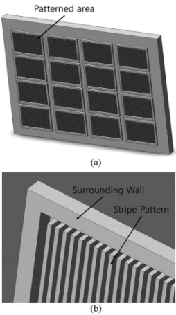
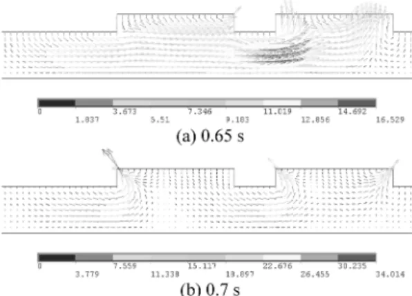
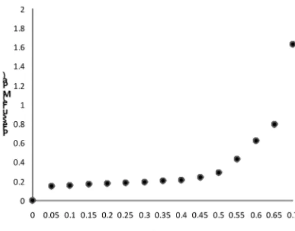
First, a simple model considering the surrounding wall was established in order to simulate effectively and reduce the computing time. Then, the volume of fluid (VOF) and grid deformation method were utilized to calculate the free surfaces of the resist flow based on an Eulerian grid system. From the simulation, the velocity fields and the imprinting pressure during the filling process in the NIL were analyzed, and the effect of the surrounding wall and the uniformity of residual layer were investigated.

Key Words : Nanoimprint Lithography, Large Area, Residual Layer Uniformity

1. Introduction

Nanoimprint lithography (NIL) is one of the most versatile and promising technology for micro/nano- patterning due to its simplicity, high throughput and low cost [1, 2]. It can be utilized in semiconductor, display and solar cell industry. A typical process of NIL is that a mold with nanostructures on its surface is pressed against a substrate coated with a resist material, to replicate patterns by physical or chemical methods. In general, NIL is classified into two types according to the resist materials and the process conditions: thermal NIL and ultraviolet NIL (UV- NIL) [3, 4]. Thermal NIL is the earliest and most mature one. Thermal NIL sets the thermal cycle to heat up the imprinted resist polymer over its glass transition temperature, while the high pressure is preserved during the hot embossing procedure.

Recently, one of the major trends of NIL is large- area patterning. Especially, the research of the application to TFT-LCD field has been increasing.

Generally it is expected that NIL achieves productivity improvement by decrease of tact time and elevation of yield rate. Technical difficulties to keep the uniformity of the residual layer, however, become severer as the imprinting area increases more and more; the problems such as difficulty of uniform pressing to the mold and irregularity of pattern size and shape on mold results in the non-uniform residual layer on the substrate [5]. Moreover, considering the dimensional tolerances of the substrate thickness and the stage flatness, the non-uniformity of the residual layer becomes more serious.

In this paper, a numerical study for a large area NIL (the 2

nd

generation TFT-LCD glass substrate (370×470 mm)) to analyze the filling process and to inprove the uniformity of residual layer was performed. By using the commercial finite element analysis code ANSYS,

E-mail : [email protected]

(2)

simulations were performed for fluid flow of NIL as in the authors’ previous research [6]. To simulate effectively and reduce the computing time, a simple model with surrounding wall was chosen. For a simulating filling behavior, an unsteady incompressible flow with free surfaces was solved on an Eulerian grid to track the deforming interface between the polymer resist and mold by using the volume of fluid (VOF) and grid deformation methods. Among various factors causing the non-uniformity of the residual layer, effects of the surrounding wall in the patterned area of the mold on the uniformity of residual layer of the substrate were investigated.

2. Simulation Modeling

Generally, a mold in large area nanoimprint lithography has multiple small patterned areas for the purpose of high throughput as shown in Fig. 1. Each area has micro/nano size patterns and the surrounding wall. In this work, only the stripe pattern (line-and- space) is to be concerned. The initial resist shape is assumed to be rectangular with constant initial height and only one patterned area with a stripe pattern and a surrounding wall is to be considered. As the cross- sectional shape of the mold is constant in one direction, as shown in Fig. 1 (b), two-dimensional analysis is possible. Moreover, as it is almost impossible to model the mold with numerous stripe pattern shapes, the mold is replaced by regular 3 line- and-spaces and a surrounding wall with symmetric boundary condition as shown in Fig. 2. This simple model is designed just for investigating the effect of existence of surrounding wall on the filling process in NIL. By ignoring the dynamic effects, the polymer flow was commonly viewed as an incompressible flow. The computation domain and the associated boundary conditions of the simulation are as follows;

(vf) represents non-slip boundary conditions, (df) is fixed displacement boundary, and (s) indicates sym- metric boundary conditions. To simplify the analysis, the mold was assumed to be isothermal and rigid, the imprinting velocity was constant, and the air pressure of the cavity was ignored.

The Navier-Stokes equations are numerically

solved by using the commercial finite element analysis code ANSYS.

(1) (2) where are the density, the viscosity, and the gravi-

ρ∂ v

--- ρ v grad ∂t + ( ⋅ )v grad P

– + ρg η grad divv + ( )

=

divv = 0

Fig. 1. (a) Schematics of a large area mold, containing multiple patterned areas (b) A patterned area with a stripe pattern and a surrounding wall.

Fig. 2. A simple model investigating the effect of existence

of surrounding wall on the filling process in NIL.

(3)

tational acceleration, respectively. The resist, with viscosity 10

4

Pa·s and density 1.19 g/cm

3

was utilized in this work.

The fluid element of ANSYS was employed to model the resist flow during imprinting process. The 4 node 141 fluid element was implemented to represent the resist flow. The VOF and the arbitrary Lagrange and Euler method (ALE) of solution conditional options were activated in this simulation.

In the VOF analysis, ANSYS uses an advection algorithm for the volume fraction to track the evolution of the free surface. The volume fraction value for each element varies from zero to one, where zero denotes an empty or void element and one denotes a full or fluid element. The values between zero and one indicate that the corresponding elements are the partially full or surface elements, and the free surface can thus be determined by the distribution of the volume fraction. The ALE is a numerical method to enable grid deformations and avoid elements from large deformation in solution procedures.

Fig. 3 illustrates the mesh layout of FEM simulation, where gray elements correspond to resist flow (volume fraction = 1.0, means flow occupied with element), and the white elements relate to air (volume fraction = 0.0) in initial condition.

3. Results and Discussions

Fig. 4 shows the simulated free surface shapes of the resist during filling in progress, under the process conditions of constant velocity V = 2 mm/s, and the following mold shape; 40 mm width of surrounding wall, 7 mm width of mold teeth, 20 mm width of mold cavity, 3 mm height of mold cavity and 8 mm height of initial resist. Due to the symmetry, half width of the surrounding wall was represented. The surface tension and gravity effect are considered and the value of surface tension considered is 29.7 mN/m.

The resist appears to have first filled the mold cavity near to the surrounding wall. At 0.6 s, the mold cavity near to the surrounding wall was almost full of the resist; on the other hand the mold cavity in the center was not.

Fig. 5 represents the simulation results of velocity vector distributions of the left half region of the model under the same conditions shown in Fig. 4.

Fig. 5 (a), (b) and (c) show resist flow characteristics at elapsed time 0.2 s, 0.4 s and 0.6 s, respectively. The

Fig. 3. FEM model in initial condition where gray elements correspond to resist flow, and the white elements relate to air.

Fig. 4. Free surface shapes at time passing under the conditions of V = 2 mm/s.

Fig. 5. Velocity vector distributions at time passing under

the conditions of V = 2 mm/s.

(4)

resist material underneath the surrounding wall and the mold teeth squeezed by the mold results the flow in Y direction movement. The flow gradually turns into X direction and then move to cavity center. As the contact area between the surrounding wall and the resist is larger than that between the mold teeth and the resist, the resist flow underneath the surrounding wall seems to be dominant. So, as shown in Fig. 5, at early stage of the filling process, the mold cavity near to the surrounding wall was first filled with the resist. After then, the next mold cavity would be full sequentially.

Fig. 6 presents the imprinting pressure evolution with respect to elapsed time during the imprinting process under the conditions described previously. At early stage, a little pressure is necessary for the filling process. When the mold cavity near to the surrounding wall was nearly full of the resist, the pressure grows and then increases steeply. Usually this stage (at time = 0.6 s in this figure) is thought to be end of the filling process, which is one of the main causes for the non-uniform residual layer of the resist.

Similar results were also reported in reference [5, 7]. In the reference 5, it was reported that the molding of the meander like structure was incomplete and resulted in a large unstructured area in the center. The nanostructured region was surrounded by a large unstructured area, that is the surrounding wall, and the majority of material flowed from the boundaries.

For this case, the squeeze flow in the intercavity regions was able to be neglected. The reference 7 dealt with a typical case where the grating was surrounded by a large unstructured area. Profilometric height measurements of a cross section schematically

represent in nm indicated resist thickness variations near and within the grating border.

If the mold is moved down at the same speed after the time 0.6 s when the mold cavity near to the surrounding wall is almost full of the resist, the free surface shapes of the resist as shown in Fig. 7 can be obtained. At the time 0.65 s, the filling of the mold cavity in the center is still on progress. And at the time 0.7 s, it is thought that the mold cavity in the center is also almost full of the resist.

Fig. 8 (a) and (b) show the simulated velocity vector distributions of the left half region of the model at the time 0.65 s and 0.7 s, respectively. The distribution of the resist flow at the time 0.65 s is similar to that at the time 0.6s in Fig. 5 (c), and it can be seen that the mold cavity in the center is on filling progress. At the time 0.7 s, however, the mold cavities both near to surrounding wall and in the center have similar velocity vector distributions, and it can be clearly seen that the mold cavity in the center is almost full of the resist.

Fig. 6. Imprinting pressure evolution with respect to elapsing time.

Fig. 7. Free surface shapes at time 0.65 s and 0.7 s under the conditions of V = 2 mm/s.

Fig. 8. Velocity vector distributions at time passing under

the conditions of V = 2 mm/s.

(5)

Fig. 9 shows the imprinting pressure evolution including the time 0.7 s. The pressure needed for imprinting until the time 0.7 s after the time 0.6s increases very much steeply, and is about 2.6 times as much compared to that at the time 0.6s (at 0.6 s, 0.63 MPa; at 0.7 s, 1.63 MPa). To improve the uniformity of residual layer of a large area nanoimprint, after the time needed to make full the cavity adjacent to the surrounding wall, it can be seen that more imprinting process should be required; in this work, 17 % (0.1 s/

0.6 s) more time and 2.6 times more pressure.

4. Conclusions

In order to understand resist flow phenomena in a large area NIL, and to elevate the uniformity of residual layer, a numerical analysis by using ANSYS, was carried out. From the simulation, the following conclusions can be drawn.

1. As it is almost impossible to model the mold with numerous stripe pattern shapes, the mold is assumed to be regular 3 line-and-spaces and a surrounding wall. Through this simple model, it is possible to investigate the filling process of a large area NIL effectively.

2. The calculated free surface shapes and velocity vector distributions tell us that as the contact area between the surrounding wall and the resist is larger than that between the mold teeth and the resist, the resist flow underneath the surrounding wall seem to

be dominant, and that the mold cavity near to the surrounding wall was first full of the resist and then, the next mold cavity would be full sequentially, which is one of the main causes for the non-uniform residual layer of the resist

3. To improve the uniformity of residual layer of a large area NIL, after the time needed to make full the cavity adjacent to the surrounding wall, it can be seen that more imprinting process should be required; in this work, 17 % (0.1 s/0.6 s) more time and 2.6 times more pressure.

Acknowledgment

This work was supported by the Soonchunhyang University.

References

1. Chou, S. and Krauss, P., “Imprint lithography with sub-10nm feature size and high throughput,” Micro- electronic Engineering., Vol. 35, pp. 237-240, 1997.

2. Guo, L. J., “Recent progress in nanoimprint technol- ogy and its applications,” J. Phys. D: Appl. Phys., Vol. 37, pp. R123-R141, 2004.

3. Kim, N. W., Kim, K. W., and Sin, H.-C., “Finite ele- ment analysis of low temperature thermal nanoim- print lithography using a viscoelastic model,” Micro- electronic Engineering., Vol. 85, pp. 1858-1865, 2008.

4. Kim, N. W., Kim, K. W., and Sin, H.-C., “A mathe- matical model for slip phenomenon in a cavity-filling process of nanoimprint lithography,” Microelectronic Engineering., Vol. 86, pp. 2324-2329, 2009.

5. Heyderman, L. J., Schift, H., David, C., Gorbrecht, J., and Schweizer, T., “Flow behaviour of thin polymer films used for hot embossing lithography,” Microelec- tronic Engieering, Vol. 54, pp. 229-245, 2000.

6. Kim, N. W., Kim, K. W., and Lee, W.-Y., “A Numer- ical Analysis of Polymer Flow in Thermal Nanoim- print Lithography,” Journal of the Semiconductor &

Display Technology, Vol. 9, No. 3, pp. 29-34, 2010.

7. H. Schift, L. J. Heyderman, M. Auf der Maur, and J. Gobrecht, “Pattern formation in hot embossing of thin polymer films,” Institute of Physics Publishing, Nanotechnology, Vol. 12, pp. 173-177, 2001.

접수일: 2010년 11월 12일, 심사일: 2010년 11월 25일 게재확정일: 2010년 11월 30일

Fig. 9. Imprinting pressure evolution with respect to elapsing

time.

수치

Fig. 1. (a) Schematics of a large area mold, containing multiple patterned areas (b) A patterned area with a stripe pattern and a surrounding wall
Fig. 8 (a) and (b) show the simulated velocity vector distributions of the left half region of the model at the time 0.65 s and 0.7 s, respectively
Fig. 9 shows the imprinting pressure evolution including the time 0.7 s. The pressure needed for imprinting until the time 0.7 s after the time 0.6s increases very much steeply, and is about 2.6 times as much compared to that at the time 0.6s (at 0.6 s, 0.

참조

관련 문서

• 이명의 치료에 대한 매커니즘과 디지털 음향 기술에 대한 상업적으로의 급속한 발전으로 인해 치료 옵션은 증가했 지만, 선택 가이드 라인은 거의 없음.. •

After choosing the type of bike, the next step is the right bike size. the right size for you from

44 글의 첫 번째 문장인 The most important thing in the Boat Race is harmony and teamwork.을 통해 Boat Race에서 가장 중요한 것은 조 화와 팀워크임을

Now that you have the right bike for you, it is important to learn the right riding position.. A poor riding position can lead to injuries

44 글의 첫 번째 문장인 The most important thing in the Boat Race is harmony and teamwork.을 통해 Boat Race에서 가장 중요한 것은 조 화와 팀워크임을

12 that절 내의 주어를 문장의 주어로 쓰고 that절 내의 동사를 to부정사로 써 서 수동태 문장을 만들 수 있다... 13 반복되는 the reason을 관계대명사 which로 바꿔주고

Now that you have the right bike for you, it is important to learn the right riding position.. A poor riding position can lead to

Since every classical or virtual knot is equivalent to the unknot via a sequence of the extended Reidmeister moves together with the forbidden moves, illustrated in Section 2,