The development of a high efficient transcranial magnetic stimulation adopted real time-
charging-discharging circuit
Whi-Young Kim*, Sung-Joon Park★
Abstract
In this study, we have been proposed the new type of a transcranial magnetic stimulation adopted a variable voltage capacitor with Cockcroft-Walton circuit and constant-frequency current resonant half-bridge inverter.
This a transcranial magnetic stimulation has some merits compared with the conventional one. First, it doesn't require the high voltage transformer. And second, it has less switching losses, compact size and capability in adjusting the transcranial magnetic stimulation output energy precisely. In this paper, we have performed the output characteristics of a transcranial magnetic stimulation system which is well known as magnetic stimulation.
The tested results are described as a function of pulse repetition rate and switching numbers of the half-bridge inverter.
Key words: Cockcroft-Walton circuit, TMS(Transcranial magnetic stimulation), Pulse repetition
* Department of Biomedical Engineering, Dongju College University
★ Corresponding author
Power Generation Division, Korea Hydro-Nuclear Power
Manuscript receved June. 10, 2010 ; receved June. 29, 2010
I. Introduction
Transcranial Magnetic Stimulation (TMS) is a new tool that allows non-invasive stimulation of biological systems. This technique uses specific equipment, in which the most visible element is the coil that generates the magnetic pulses. The coils is driven by high-intensity current that is rapidly turned on and off through the discharge of capacitors. This current produces a time-varying magnetic field that lasts for about 100 to 200 microseconds. The typical magnetic field strength is about 2 Tesla. Among the MS techniques, the Transcranial Magnetic Stimulation (TMS) is a tool for neuroscience which allows non-invasive stimulation of peripheral nerves and cerebral cortex.
Its purpose is to create a pulsed electric current induced by a time-varying magnetic filed and it has
appeared in 1985 as a brain mapping tool. .It is nowadays considered as an established research toolin the cognitive neurosciences field, including the study of perception, attention, learning, plasticity, language and awareness.
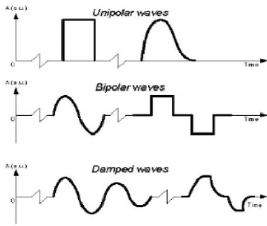
Fig. 1. Traditional pulse wave apparatus
TMS has also being used in the study and treatment of several neuropsychiatric disorders, such as movement disorders, epilepsy, both unipolar and
Fig. 2. Transcranial Magnetic Stimulation bipolar disorders, anxiety disorders and
schizophrenia. Research aiming the use of TMS in other types of disorders and also directed to specific population sets has been reported for several times in the last few years.
The use of this technique on biological tissues, requires a magnetic field as focal as possible to stimulate only well defined areas. The effect of the MS depends on the geometry and orientation of the induced electric field, as well on the current pulse waveform delivered by the stimulator. These factors are very important to define the equipment requirements and characteristics, namely the size and geometry of the coil and the topology of the power supply[1-2].
The main objective behind this work is to develop new and state of the art magnetic stimulation equipment. The main effort has been focused on the design of the coil and its cooling system [to be published] and in the development of the power supply. The design and implementation of the MS coil has been done using modern computational techniques to optimize their electrical and
geometrical characteristics. The tested topology of the power supply fills the requirements to be implemented in MS systems.
In connection with these, a single magnetic pulse energy of magnetic stimulation is a significant element of Transcranial Magnetic Stimulation manufacturing. However, when we establish Transcranial Magnetic Stimulation pulse repetition ratio, the change rate of the single pulse beam energy becomes worse as the repetition ratio increases. Consequently, it is necessary that the energy fluctuation should be minimized by controlling the capacitor charging voltage. In this study, a new method of Transcranial Magnetic Stimulation output stabilization by the monitoring of capacitor charging voltage is proposed.
Ⅱ. Magnetic stimulation
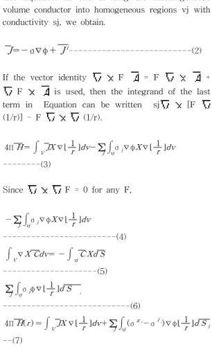
The current density throughout a volume conductor gives rise to a magnetic field given by the following relationship (Stratton, 1941; Jackson,
1975): where r is the distance from an external field point at which is evaluated to an element of volume dv inside the body, dv is a source element, and is an operator with respect to the source coordinates.
4ΠH= ⌠⌡VJX ∇[ 1r ]dv ---(1)
Substituting Equation (1), which is repeated here, into Equation (2) and dividing the inhomogeneous volume conductor into homogeneous regions vj with conductivity sj, we obtain.
J=- σ∇φ+ Ji---(2)
If the vector identity F = F +
F is used, then the integrand of the last term in Equation can be written sj [F (1/r)] - F (1/r).
4ΠH= ⌠⌡VJX ∇[ 1r ]dv-∑J⌠⌡vjσj∇φX∇[ 1r ]dv ---(3)
Since F = 0 for any F,
-∑J⌠⌡vjσj∇φX∇[ 1r ]dv
---(4)
⌠⌡V∇X Cdv= - ⌠⌡vjC Xd S
---(5)
∑J⌠⌡vjσjφ∇[ 1r ]d S j
---(6)
4ΠH( r ) = ⌠⌡VJX ∇[ 1r ]dv+∑J⌠⌡vj(σgj-σfj)∇φ[ 1r ]d Sj --(7)
2-1. Magnetic stimulation Coil
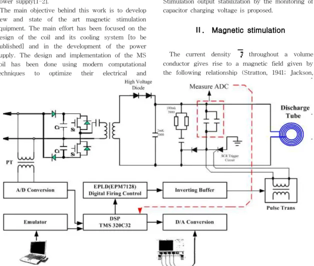
Fig.2 shows the schematic diagram of a pulsed Transcranial Magnetic Stimulation. The coil probe consists of a single elliptical type, which has two bronze pipe along the optical axis for magnetic field vibration on both sides. Transcranial Magnetic
Stimulation and coil are located at the focus. The inner coil surface with mebrane coating after surface cutting has a good reflection with a wavelength range that excites Transcranial Magnetic Stimulation mediums in the coil probe reflection magnetic field[3-5].
Heating by Transcranial Magnetic Stimulation mediums as well as by probe due to long magnetic stimulation operations, effects the temperature distribution of a medium, gives spatial changes of reflective index, changes the output pulse type and severely damages the medium. To prevent these results, the Transcranial Magnetic Stimulation, coil, and coil probe should be cooled down with cooling water configuration, a magnetic stimulation is comprised of a magnetic stimulation coil which contains all the magnetic elements, a power supply to drive the magnetic source, and a cooling system.
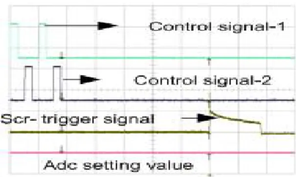
Fig. 3. waveform of control signals apparatus
A magnetic stimulation coil is composed of a magnetic stimulation and a coil. In this research, we have adopted a double power circuit by using voltage division capacitors as shown in fig 3 and made it operate as half bridge type by adding a resonance circuit. At this time, an on-and-off operation of the switch occurs when the current in the switch is zero. So the power loss by operating the switch is almost zero. Switch S1, S2 come into the serial action of on and off.
Fig. 4. waveform of setting signals
IGBT(BSM75GB120DN2), which operates from 1kHz to tens of kHz, is used in the switching element. It is a half bridge package type, which has 1600V of regular voltage and 130A of regular current. IGBT is a hybrid semiconductor element, which has a rapid MOSFET switching of power and electrification of BJT. Also, it is more convenient to use than BJT, due to its voltage control element with high impedance between the gate and emitter of MOSFET. Furthermore, it has a low and steady on-drop regardless of current over BJT, which produces more current than MOSFET.
CR is used as a blocking capacitor. When input capacitors C1 and C2 do not divide input voltage V1 exactly in two parts, or on-time of switches S1 and S2 do not accord together exactly, there is a risk of the transformer being saturated by the transformer's magnetic flux changes. To prevent these occurrences, we dismiss the DC elements that produce a lack of balance in flux change by adding a blocking capacitor between input voltage and transformer.
Fig. 5. Display of PCB circuit apparatus
The control circuit uses as shown in fig 5-7. The
voltage charged in the capacitor should be maintained uniformly for Transcranial Magnetic Stimulation output. First, we put on SW1 and SW2 signals.
Then, we read capacitor and charging voltage and put these values in PIC through Low Pass Filter(LPF). After that, these values are expressed in letter LCD instantly, and are loaded into SCR signals through PIC treatments.
Fig.6. Waveform of coil probe (10hz)
Fig. 7. Waveform of coil probe (30hz)
The signals in fig 3, 4 are PIC, IGBT and SCR operating signals. Coil and a magnetic stimulation coil are placed at the focus of elliptical cavity. In elliptical cavity, all rays emanating from the magnetic source coil are transferred to the magnetic stimulation. Coil are placed at the ends of the bronze pipe. In order to keep magnetic stimulation action, cooling of the coil and bronze pipe is accomplished by circulating water. The integration is performed with the vector dl along the coil windings C and m0 = 4p´ 10-7 H/m is the permeability of free space. The pulses of current are generated with a circuit containing a discharge capacitor connected with the coil in series by a thyristor. With the capacitor first charged to 2-3 kV, the gating of the thyristor into the conducting state will cause the discharging of the capacitor through the coil. The resulting current waveform is typically a damped sinusoidal pulse that lasts about
Fig. 12. waveform of sense and power pulses 300 ms and has a peak value of 5-10 kA.TMS
proved valuable for probing the motor pathways: in healthy subjects, stimulation over the motor cortex causes twitches in hand muscles in about 25 ms, while many neurological conditions manifest slower conduction. Another important characteristic of TMS is that it is painless, the subject usually feeling only a not uncomfortable sensation of scalp being pinched. Since 1985, magnetic stimulator technology has remained mostly unchanged. The 8-shaped coil induces a more concentrated electric field than the circular coil, resulting in better control of the spatial extent of the excitation. Another important development is repetitive TMS (rTMS) capable of delivering trains of stimuli at 1-50 Hz. rTMS was first produced by Cadwell Laboratories in 1988 and is today one of the most quickly growing areas of TMS research.
Ⅲ. Experimental Result
Fig 10 shows the inverter output current through LM, In this experiment, load capacitors and control equipments are insulated by photo couplers, and are used as input. These input signals are read by letter LCD, and then instantly managed by FPGA.
Fig. 10. waveform of current, voltage, capacity
Fig. 11 setting of magnetic stimulator apparatus
The current pulse is measured by ES300C of ASS Co. Fig 11 shows a wave current ir that is generated by resonance between Cr and Lr, when IGBT is operated by a signal occurring from PIC. A large amount of resonant currents flow initially because the load capacitor voltage is zero. Recently, we have found that resonant current reduces when the capacitor is gradually charged. Then, when the set point is reached, the current reduces and becomes zero. After that, IGBT operating ends, and the mode changes from capacitor charging mode to capacitor discharging mode as the trigger signal of SCR in the second side is subjoined.
Fig. 13. waveform of switch off and FRD
Fig. 14. waveform of smart skip and senses
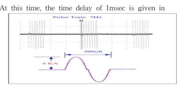
Fig. 15. waveform of pulse train 7hz (current) At this time, the time delay of 1msec is given in
order to complete the task. When the task of half bridge converter ends, the discharge mode of the second side starts.
Fig 12 waveform of sense and power pulses depicts a discharge waveform of a flashlamp measured by current transformer when the
magnetic stimulator has been oscillated continuously.
It shows the uniform waveform of the coil probe.
When we amplify it in 50 μsec, its Full Width at Half Maximum(FWHM) is about 150 μsec.
Fig 13 waveform of switch off and FRD shows the comparison test results between our previous sequential charge and discharge circuits, and our suggested circuit. In reference to the Transcranial Magnetic Stimulation output, a 15% alteration ratio is revealed. That difference of output power is caused by the charging process of the load capacitor where the current originated from rectification, resistance, inductor, and SCR switch.
The input energy of the load capacitor is so inaccurate that the desired energy cannot be exactly stored. However, the proposed circuit can store digitalized energy by using a feedback system, which can precisely measure the load capacitor energy. This method produces a stable output within 4% alteration ratio as compared with our
previous one.
Fig 14 waveform of smart skip and senses shows the results of individual output energy stability tests. This figure indicates the output energy changing ratio. The actual graph has no changes in energy levels, but it show larger deviation in small changes as the total average output is low. In exceptional cases, as the load capacitor input voltage is 700V, some larger output change is obtained. Especially, the best output error range of the single pulse has achieved 2.3% when the charging voltage is 700V.
Ⅳ. Conclusion
In this study, the Transcranial Magnetic Stimulation has been investigated as adjusting the firing angle of SCR and TRIAC using a Zero Crossing Switching(ZCS) detecting method and Programmable Integrated Controller(PIC) one-chip microprocessor in AC power line. And the output stabilization of the Transcranial Magnetic Stimulation by the monitoring of capacitor charging voltage circuit has been studied to find out the optimal pulse parameters such as a blocking capacitor, a total input energy and switching frequency. The obtained results are as follows. The obtained Transcranial Magnetic Stimulation output energy per pulse is approximately 1tesla. It can generate beam with very long pulse duration of 3 msec because of its long discharge time, which can be used in surgery and medicine such as skin rejuvenation and tissue type ablation. The maximum Transcranial Magnetic Stimulation is 350W at the total pressure of 18Torr, the pulse repetition rate of 6Hz, and the gas mixture. The maximum Transcranial Magnetic Stimulation power of approximately 400W is obtained when the trigger pulse is applied to TRIAC gate with a firing angle close to 90° and the pulse repetition rate of 60Hz, that is at the time of the peak voltage of the AC line. We found that the magnitude of the input peak voltage is more important than the discharge time length.. In Transcranial Magnetic Stimulation system, it can be obtained the error range of output within compared with previous sequential charge
and discharge method that has a 15% output error range. In particular, the optimal output error range of the single pulse has obtained a 2.3%
improvement at the charging voltage of 700V.
REFERENCES
[1] George MS, Nahas Z, Kozel FA, et al.
Mechanisms and the current state of transcranial magnetic stimulation. CNS Spectrums 2003;8:496-514.
[2] Barker AT, Jalinous R, Freeston IL.
Non-invasive magnetic stimulation of the human motor cortex. Lancet 1985;1:1106-1107.
[3] Migita K, Uozumi T, Arita K, Monden S.
Transcranial magnetic coil stimulation of motor cortex in patients with central pain. Neurosurgery 1995;36:1037-1039.
[4] Rollnik JD, Wustefeld S, Dauper J, et al.
Repetitive transcranial magnetic stimulation for the treatment of chronic pain a pilot study. Eur Neurol 2002;48:6-10.
[5] Kim W-Y, Park S-J. International journal of maritime information and communication sciencs
"development of pocket insertion style magnetic curer that apply 2loop 3pulsed variable magnet type probe for Uninary treatment" march 2008, vol 6, no.1, pp.73-79.
BIOGRAPHY Whi-Young Kim(Non Member)
1991 : MS degree in Electrical Engineering, DongA University.
2001 : Ph. D degree in Electrical Engineering, Pusan National University.
2001~Present :Dongju College University
Sung-Joon Park(Member)
2000 : BS degree in Electrical Engineering, Dongeui University.
2002 : MS degree in Electrical Engineering, Pusan National University.
2009 : Ph. D degree in Electrical Engineering, Pusan National University.
2002~2003 : Research Engineer, LG Electronics Institute of Technology.
2004~Present : Korea Hydro-Nuclear Power Company.