Vol.14, No.2, pp.44-49 (2020)
Structural Design and Analysis of Connecting Part for Vertical Wind Turbine System Blade
Hyunbum Park1,†
1School of Mechanical Convergence System Engineering, Kunsan National University
Abstract
This work is intended to develop a flapping-type vertical wind turbine system that will be applicable to diesel generators and wind turbine generator hybrid systems. In the aerodynamic design of the wind turbine blade, parametric studies were performed to determine an optimum aerodynamic configuration. After the aerodynamic design, the structural design of the blade was performed. The major structural components of the flapping-type wind turbine are the flapping blade, the connecting part, and the stopper. The primary focus of this work is the design and analysis of the connecting part. Structural tests were performed to evaluate the blade design, and the test results were compared with the results of the analysis.
Key Words: Flapping Type, Wind Turbine Blade, Structural Design, Structural Analysis
1. Introduction
The rapid development of modern society has resulted in increased energy consumption, as well as rising demand for electricity generation. Existing energy sources in the power industry include hydropower, thermal energy, nuclear energy, and gas turbine energy, all of which lead to environmental pollution and the depletion of natural resources. As a result, there is increasing interest in environmentally friendly and economical energy sources. According to the International Energy Agency, South Korea ranks 10th worldwide in the countries emitting greenhouse gases, and there is intense pressure from the international community to reduce carbon emissions. The most effective carbon emission reduction method is conversion to renewable energy. South Korea’s current renewable energy penetration rate, including that of wind power, is very low, with a renewable energy share of only 1.7%. Among the various renewable energy sources, wind power has the lowest power generation cost and highest technical maturity relative to other sources. In particular, in the
field of aerodynamic design, aeronautical engineering
knowledge serves as the basis for further development.
Research on wind turbine blades can be divided into studies on vertical and horizontal axis blades. This study adopted the vertical axis type, which is relatively easy to manufacture, and analyzed the findings of recent domestic and overseas research.
In overseas studies, Wu et al. studied certification and test technology for small vertical axis wind turbine blades in Taiwan [1]. Marinic-Kragic et al. derived an optimized shape for a flexible vertical axis blade, differentiated from the existing rigid shape, and performed a numerical analysis [2].
Shah et al. analyzed annual power generation trends by examining the design and performance of vertical axis wind turbine blades [3].
Among studies in Korea, Kim et al. investigated the shape and structural design of a 6-kW-class vertical axis wind turbine [4]. Choi et al. studied the optimization of the structure of a small vertical axis wind turbine blade using the response surface method [5]. Park et al. designed the composite structure of a small vertical axis wind turbine blade and then performed the manufacturing and test evaluation [6].
This study involves the development of a flapping-type wind turbine blade to develop a power generation device that combines a conventional diesel engine generator and a vertical offshore wind turbine system. A study on the improvement of the connecting part was performed, reflecting the results of previous research on blade structural design [7]. A drag-type Received: Feb. 01, 2019 Revised: Feb. 14, 2020 Accepted: Mar. 10, 2020
† Corresponding Author
Tel: +82-10-2635-4669, E-mail: [email protected]
Ⓒ The Society for Aerospace System Engineering
blade was selected for this study. Though lift-type blades typically have high efficiency, the technique proposed in this study is intended for power generation in marine floating systems for offshore mariculture. Since a cylindrical structure is suitable for the power generation system applied to a mariculture farm, the drag type was selected as the vertical axis cylindrical shape. The drag type has better starting torque than that of the lift type. Thus, while its efficiency is lower than that of the lift type, it can start with even low wind speeds in the ocean and provide continuous power generation.
2. Aerodynamic design of blade
The procedure for wind turbine blade design is as follows:
the system specifications are established, aerodynamic design is performed, and then the structural design is performed. First, aerodynamic design is performed, which determines the blade size, number of blades, and blade speed ratio from the design requirements. After the aerodynamic design, the degree of satisfactory aerodynamic performance is evaluated using aerodynamic analysis. After examining the level of satisfaction with the design requirements, the design is either confirmed, or inadequate aspects are improved. After completing the aerodynamic design, the structural design is undertaken. The structural design requirements are analyzed, structural design loads are derived, and the structure is designed. Based on the structural design, a static load analysis, natural frequency analysis, buckling analysis, and fatigue life analysis are conducted to confirm the stress and displacement distribution, thereby examining the structural safety of the blade. After the structural design, a prototype is manufactured, structural tests are conducted, and the structural analysis results are compared to verify the validity of the analysis results and confirm the design. The power generation system used in this study is a hybrid system combining a wind turbine system and diesel power generation system, and the blades are flapping-type. The rated power is 5 kW, and the rated wind speed is 12 m/s.
Using reference sources [8, 9], the shapes of existing flapping blades were analyzed and used to examine the validity of the aerodynamic design plan. Flapping-type blades include a type in which a braking device (stopper) is mounted after the blade is rotated and a type in which it is not mounted.
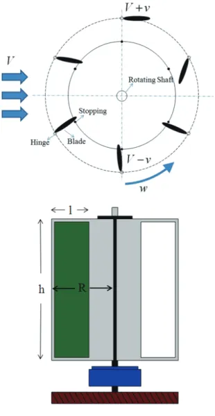
Fig. 1. Flapping type wind turbine blade.
Wind is applied to a square plate on which several wind turbine system blades developed in this study are applied, thereby generating drag and thus torque. The rotating blade has a structure that rotates with the wind and then hits the final braking device. An advantage of this wind turbine blade type over other wind turbine system blades is that directionality is not restricted. Fig. 1 shows the detailed shape of the flapping- type wind turbine blade developed in this study. In the figure, V indicates the wind speed, R is the radius of the mounted blade, l is the horizontal length of the blade, and h is the vertical length of the blade.
As impact occurs during operation, the vertical blade used in this study is structurally safe when divided into several partitions rather than composed of a single square plate. As such, when determining the aerodynamic shape, the square plate was divided to derive the optimal shape. The
aerodynamic load and power of the vertical axis wind turbine blade are calculated using the following equation. A drag coefficient Cd of 2.3 was adopted from reference [8].
(1)
(2)
where C is the drag coefficient, V is the wind speed, and S is the area.
When the blade square plate is divided, the power of the outer and inner plates is calculated using Equations (3) and (4) below. If the outer flapping blade area is defined as S1 and the inner flapping blade area is defined as S2, the power of each plate is defined by the radius R. The total power of all blades can be calculated by calculating the power of each blade.
Outer flapping blade area: S1
(3)
where ,
Inner flapping blade area: S2
(4)
where ,
Fig. 2. Power variation versus number of blades according to surface partition.
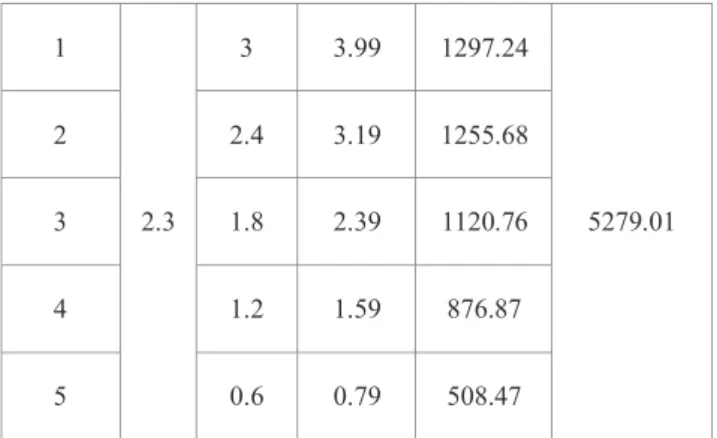
Table 1. Calculated Blade Power.
Station C1 R [m] [m/s] Station
Power Total Power [W]
1
2.3
3 3.99 1297.24
5279.01
2 2.4 3.19 1255.68
3 1.8 2.39 1120.76
4 1.2 1.59 876.87
5 0.6 0.79 508.47
Based on the theory presented above, this study involved calculating the changes in power when the inner partitions of the flapping blade plate are divided into numerous shapes, and analyzing the change in power with the entire square plate.
According to the power calculations, when the blade inner partitions are divided from 2×2 to 5×5, the total change in power was analyzed using the power calculations when divided from 3×2 to 8×2. The change in total power with respect to the number of blades is presented in the graph in Fig.
2. As the blade divisions increase, the clearance between the frames increases, thus somewhat reducing the power. As the blade used in this study has a required power of 5000 W, a 5- blade structure was considered suitable to generate the required power and to ensure structural safety after considering factors such as structural impact. Table 1 presents the final calculations for the 5 × 2 shape and Fig. 3 shows the final blade shape design. The final shape has a width of 5.2 m and length of 5.6 m.
The overall system efficiency was assumed as follows. Based on the data in reference [8], which indicate that the maximum turbine efficiency of a vertical wind turbine is 30–35%, the turbine efficiency of the vertical centrifugal wind turbine was assumed to be 35%. Considering a generator efficiency of 90%, a mechanical efficiency for power transmission of 70%, and inverter efficiency of 90%, the energy conversion efficiency of the overall system is 16.1% when predicting the available power generation capacity according to wind speed changes.
Fig. 3. Designed blade configuration.
3. Structural design of blade connecting part
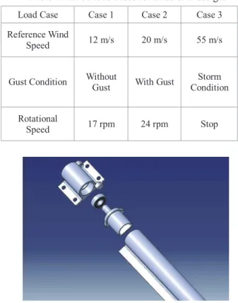
In structural design, loads can be divided into aerodynamic load and centrifugal load due to rotation. Under normal typhoon load conditions, the blade is kept stationary; therefore, extreme conditions and wind gusts are used for the structural design load. Table 2 shows three structural load cases [7].
Among various load cases, these three were determined to be the most severe loads according to wind turbine design regulations and were thus analyzed in this study. Other loads were confirmed to fall below these three cases. In this study, Case 2 (reference wind speed of 20 m/s, the rotational speed of 24 rpm, gust condition) was applied as the structural design load.
The most important part in the structure of flapping-type wind turbine system blades is the braking device for the rotating blade. The blade structure must also be light without undergoing deformation due to drag. Accordingly, the reaction force and deflection of the braking device were calculated for each case considered in the aerodynamic design. The blade material was steel, and the braking device was positioned at 5 cm from the blade root.
In terms of the blade hinge, it is crucial to design a braking device that can withstand the impact of the blade reaction force. The blade reaction force was calculated at 2,330 N using Equation (5), and ADC12, an alloy for die casting, was selected as the hinge material using the position of the braking device and the blade reaction force.
(5) where q is the distribution load, L is the length from the left
end of the blade to the braking device, and a is the length from the braking device to the right end.
Table 2. Three load cases for structural design.
Load Case Case 1 Case 2 Case 3 Reference Wind
Speed 12 m/s 20 m/s 55 m/s
Gust Condition Without
Gust With Gust Storm Condition
Rotational
Speed 17 rpm 24 rpm Stop
Fig. 4. Blade hinge configuration.
Fig. 4 shows the shape of the connecting part hinge. A stress analysis was conducted with a finite element structural analysis under each load condition, which indicated that the maximum stress occurs under load case 3. The stress in this case was measured at 6.8 × 10³ N/m2, demonstrating that it is sufficiently safe, as compared to the yield strength of ADC12 of 1.85 × 10⁸ N/m2. Fig. 5 shows the stress analysis results for load case 3. Table 3 shows the mechanical properties of ADC12.
Table 3. Mechanical Properties of ADC12.
Mechanical Properties
Young’s Modulus 7.0 × 10¹⁰ N/m2
Poisson Ratio 0.346
Yield Strength 1.85 × 10⁸ N/m2
Fig. 5. Stress analysis results.
Based on an analysis of the initial design results, the following shape improvements were presented, and the design was modified accordingly. In the braking device structure, a spring is applied to mount the damper, deflection is applied toward the rear at 11° under the maximum wind speed, and a change in drag is applied to reduce the load on the structure. Applying this shape also helped to reduce the effects of noise. Moreover, to prevent structural damage due to displacement even under the maximum wind speed, the plate of the blade was changed from the existing stainless-steel material to a spring steel material.
4. Blade manufacturing
In terms of the manufacturing of wind turbine blades used for offshore wind power generation, most structures are made of stainless steel and structures without stainless steel are treated with a waterproof coating. In addition, blade holders made from aluminum are treated with an aluminum coating.
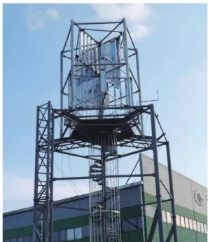
Fig. 6 shows the wind turbine blade manufacturing process and Fig. 7 shows the final manufactured shape in which the connecting part of the existing blade is improved.
Fig. 6. Manufactured blade.
Fig. 7. Prototype blade configuration.
The wind turbine blade is the drag type; it has a lower rotational speed than that of other wind turbine blades but has a better starting torque. The wind turbine blade is accordingly designed to satisfy the rated power even if the rated RPM is lower than those of other generators, and neodymium is used for the permanent magnet to achieve high efficiency. In a hybrid power generation system, the diesel generator applies mechanical torque with a diesel engine, which is applied to a synchronous generator to produce electrical power.
Furthermore, rather than running at all times, diesel generators can be turned on or off automatically or remotely, as needed.
For the hybrid power generation system that combines a small wind turbine with diesel power generation, the final design results in a system that uses a diesel generator as the main power source and links an auxiliary wind turbine that generates irregular power. This system optimizes the use of the diesel generator, thus reducing fuel costs and enabling independent power generation.
5. Performance test
Since the flapping-type wind turbine blade has a slower rotational speed than that of the lift type wind turbine blade, a gearbox is essential for efficient power generation. The speed increasing ratio was set to 1:18, in line with the rated RPM of the wind turbine and the operating area of the wind generator and according to the rated wind speed of the gearbox. Though it is ideal for testing the performance on a coast where wind resources are relatively abundant, the prototypes were installed on the ground for effective equipment monitoring.
Additionally, as a precaution against poor wind quality due to interference such as that from buildings and roadside trees, a test base with a height of 20 m was installed to avoid the impact of vortices caused by buildings and other objects.
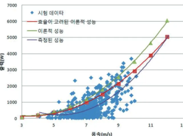
The entire test was performed over a one-month period. The maximum wind speed during the test was 10 m/s, and, when curve fitting the data generated from speeds at or exceeding 3 m/s, a power of approximately 5000 W was confirmed for a speed of 12 m/s. However, the power trends of the wind turbine differed from those of the overall performance test because of the interference of the wind turbine controller, or lack thereof. Fig. 8 shows the performance test results.
Fig. 8. Results of theoretical and tested power.
6. Conclusions
This study involved the development of a flapping-type vertical axis wind turbine system blade for a hybrid power generation system that combines a wind turbine system and diesel engine generator. Various parameters were investigated to derive an optimized aerodynamic shape during the aerodynamic design process for the blade.
After the aerodynamic design, the structural design of the blade was performed. In a flapping-type structure, the impact
is applied to the structure by the speed and rotation of incoming wind. Therefore, the critical parts are the connecting part and the braking device. Applying the proposed design plan, the connecting part was designed, and the safety was evaluated through structural analysis. The final design results indicated that the component is structurally safe.
Acknowledgements
This research was supported by Basic Science Research Program through the National Research Foundation of Korea (NRF) funded by the Ministry of Education (No.
2018R1D1A1B07043553).
References
[1] Wu, U., Lin, H., Lin, J., “Certification and Testing Technology for Small Vertical Axis Wind Turbine in Taiwan,” Sustainable Energy Technologies and Assessments, Vol. 31, pp. 34-42, 2019.
[2] Marinic-Kragic, I., Vucina, D., Milas, Z., “Concept of Flexible Vertical-axis Wind Turbine with Numerical Simulation and Shape Optimization,” Energy, Vol. 167, pp. 841-852, 2019.
[3] Shah, S., Kumar, R., Raahemifar, K., Fung, A., “Design, Modeling and Economic Performance of a Vertical Axis Wind Turbine,” Energy Reports, Vol. 4, pp. 619-623, 2018.
[4] Kim, D., Choi, H., Lee, J., Rey, G., Kim, S., Kim K., Nam, H., Lee, M., “Aerodynamic and Structural Design of 6kW Class Vertical-Axis Wind Turbine,” Journal of Fluid Machinery, Vol. 14, No. 2, pp. 52-58, 2011.
[5] Choi, C., Jin, J., Kang, K., “Structural Optimization for Small Scale Vertical-Axis Wind Turbine Blade using Response Surface Method,” Journal of Fluid Machinery, Vol. 16, No. 4, pp. 22-27, 2013.
[6] Park, H., “Study on Design, Manufacturing and Test Evaluation using Composite Materials of Vertical Axis Wind Turbine Blade,” Journal of Aerospace System Engineering, Vol. 12, No. 3, pp. 58-63, 2018.
[7] Lee, H., Kong, C., Park, H., “Development of Flapping Type Wind Turbine System for 5 kW Class Hybrid Power Generation System,” International Journal of Aeronautical and Space Sciences, Vol. 17, No. 2, pp. 167- 174, 2016.
[8] Desire Le Gourieres, Wind Power Plants, Theory and Design, Pergamon Press, UK. 1982.
[9] Kong, C., Lee, H., Kim, I., “Aerodynamic and Structural Design of A High Efficiency Small Scale Composite Vertical Axis Wind Turbine Blade,” Journal of The Korean Society for the Aeronautical and Space Sciences, Vol. 39, No. 8, pp. 758-765, 2011.