DOI: http://dx.doi.org/10.4313/JKEM.2017.30.1.37 ISSN 1226-7945 (Print), 2288-3258 (Online)
자기인가회로를 이용한 자속구속형 초전도한류기의 고장전류제한 특성 분석
고주찬, 임승택, 임성훈a
숭실대학교 전기공학부
Analysis on Fault Current Limiting Characteristics of Flux-Lock Type SFCL Using Magnetic Flux Application Circuit
Ju-Chan Go, Seung-Taek Lim, and Sung-Hun Lima
School of Electrical Engineering, Soongsil University, Seoul 06978, Korea
(Received November 21, 2016; Accepted November 22, 2016)
Abstract: In this paper, the fault current limiting characteristics of the flux-lock type SFCL (superconducting fault current limiter) using magnetic application circuit were analyzed. The flux-lock type SFCL has the structure to install the magnetic application circuit, which can increase the resistance of HTSC (high-TC superconducting element comprising) the SFCL. To analyze the fault current limiting effect of the flux-lock type SFCL through the magnetic flux application circuit, the flux-lock type SFCL either with the magnetic flux circuit or without the magnetic flux circuit was constructed and the fault current limiting characteristics of the SFCL were compared each other through the short-circuit tests.
Keywords: Flux-lock type SFCL (superconducting fault current limiter), Magnetic flux application circuit, Fault current limiting characteristics
1. 서 론
전력 수요의 지속적인 증가와 이를 공급하기 위한 발전 설비의 증가는 신재생에너지원을 이용한 분산전 원 설비의 확장으로 이어졌으며, 전력망의 효율적인 운 영과 안전을 위한 다양한 연구와 사업들이 진행되고 있다. 하지만, 복잡화되고 분산된 전력망으로 계통의 고장전류는 증가하게 되었으며, 관련 보호 설비들의 교 체에 따른 비용 상승은 고장전류를 저감하기 위한 방
a. Corresponding author; [email protected]
Copyright ©2017 KIEEME. All rights reserved.
This is an Open-Access article distributed under the terms of the Creative Commons Attribution Non-Commercial License (http://creativecommons.org/licenses/by-nc/3.0) which permits unrestricted non-commercial use, distribution, and reproduction in any medium, provided the original work is properly cited.
안들을 요구하게 되었다 [1-4]. 이러한 방안들 중의 하 나로 초전도한류기에 대한 관심이 집중되어 왔으며, 다 양한 구조와 동작원리를 갖는 초전도한류기가 개발되 어 적용되어 왔다 [4-10].
자속구속형 초전도한류기는 일본에서 처음 제안된 초전도 한류기중의 하나로 한류기를 구성하는 초전도 모듈로 외부에 별도의 전원 없이 자속을 인가함으로 써 퀜치 발생시 저항을 증가시켜 고장전류제한효과를 상승시킬 수 있는 특징을 갖는다. 이와 같은 구조와 특징은 초전도한류기를 구성하는 초전도모듈의 개수를 감소시킬 수 있는 장점이 된다 [9-12].
반면에, 자계인가회로 설치에 따른 한류기 동작 특 성 개선에 대한 검토가 필요하며, 본 논문에서는 이에 대한 유용성 검증을 위해 자계인가회로 존재유무에 따 른 자속구속형 초전도한류기의 고장전류제한 효과와
Table 1. Specifications of the flux-lock type SFCL.
Windings Value Unit
Turn number of winding1 (N1) Turn number of winding2 (N2)
60 15
Turns Turns Magnetic flux application circuit Value Unit
Turn number of winding3 (N3) Series resistance (R3)
30 0.76
Turns Ω
HTSC module Value Unit
Material Fabrication type Critical temperature (TC)
Critical current (IC)
YBCO Thin film
87 27
-
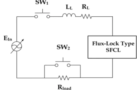
K A Fig. 1. Schematic configuration of the flux-lock type SFCL.
자속구속형 초전도한류기의 대략적인 구조를 그림 1 에 도시하였으며, 철심을 매개로 첫 번째와 두 번째 권 선은 병렬로 연결되며, 나머지 세 번째 권선은 두 개의 권선들과 독립적으로 연결된 구조를 갖는다. 초전도 모 듈은 병렬로 연결된 권선 중 두 번째 권선에 연결되 며, 자계인가회로는 세 번째 권선에 연결되어 구성된다.
자속구속형 초전도한류기 동작은 평상시와 고장발생 시의 두 가지 상태로 나누어 설명할 수 있다. 평상시에 는 병렬 연결된 두 개의 권선에서 발생되는 자속이 서 로 상쇄되어 세 번째 권선을 포함한 모든 권선에 전압 이 유기되지 않게 된다. 하지만, 고장발생으로 초전도 모듈의 퀜치 발생으로 저항이 발생하면 두 권선에서 자 속이 상쇄되지 않아 세 개의 권선 모두에서 전압이 유 기되며, 자계인가회로가 연결된 세 번째 권선에 전류가 흐르게 됨으로써 초전도모듈에 자계를 인가시킬 수 있 게 된다. 초전도모듈은 다수의 초전도소자로 구성되며, 외부자계가 증가할수록 퀜치발생시 초전도모듈의 저항 을 증가시킬 수 있게 된다.
2.2 실험구성 및 실험방법
그림 2는 자속구속형 초전도한류기의 고장전류 제한 특성을 모의하기 위한 실험회로 구성을 보여주며, 선로
임피던스 (ZL= RL+ jXL= 0.42+j0.066 Ω) 및 부하저항 (Rload=5 Ω)로 구성하였다. 고장모의를 위한 실험은 교 류전원 전압(Ein) 360 V에서 SW1을 투입한 후 SW2를 고장각 0°에서 6주기 동안 투입시켜 진행하였다.
자계인가회로를 포함한 자속구속형 초전도한류기 (flux-lock type SFCL)를 구성하는 각 권선의 권선수 와 초전도모듈의 제작 형태 및 임계값은 표 1에 나타 내었다. 자계인가회로로부터 자계를 인가하지 않은 경우와 인가한 경우에 따른 초전도모듈의 저항증가를 모의하기 위해 병렬저항(RP)을 각각 0.76 Ω과 2.3 Ω을 연결하여 단락실험을 실시하였다. 또한, 자계인가회로 를 구성하지 않고 초전도모듈 다수개를 직렬 연결을 통해 저항을 증가시킨 경우는 2.3 Ω을 연결하여 모의 하였다.
3. 결과 및 고찰
자속구속형 초전도한류기의 자계인가회로에 의한 초
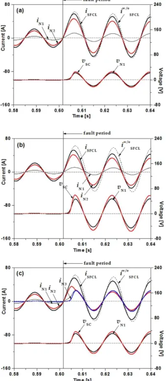
Fig. 3. Fault current limiting characteristics of the flux-lock type SFCL with either magnetic flux application circuit or not.
(a) in case that magnetic flux application circuit was not installed (RP=0.76 Ω), (b) in case that magnetic flux application circuit was not installed (RP=2.30 Ω), and (c) in case that magnetic flux application circuit was installed (RP=2.30 Ω).
Fig. 4. Voltage and current waveforms of the flux-lock type SFCL with either magnetic flux application circuit or not after fault occurrence.
전도모듈의 저항증가에 따른 고장전류제한 향상 특성 을 분석한 결과를 그림 3에 나타내었다. 먼저, 자계인 가회로가 설치되지 않은 경우, 초전도모듈의 저항이 증 가되지 않은 경우(RP=0.76 Ω)와 직렬로 초전도모듈의 개수를 늘려서 전체모듈의 발생저항을 증가시켜 모의 한 경우(RP= 2.3 Ω)의 검토결과를 그림 3(a)와 그림 3(b)에 도시하였다. 그림 3(a)와 그림 3(b)에서 비교할 수 있는 것처럼, 직렬 연결된 초전도모듈 개수를 증가 시켜서 단락을 모의한 경우 전체초전도모듈(vSC)의 전 압이 직렬 연결하지 않은 모듈의 전압보다 크게 발생 하는 것을 비교할 수 있으며, 제한되는 고장전류(iSFCL) 도 직렬 연결된 초전도모듈을 적용하여 모의한 경우에 효과가 있는 것을 분석할 수 있다.
자계인가회로를 설치하여 자계인가에 의해 한류기를 구성하는 초전도모듈의 저항이 증가된 경우를 모의한 결과를 그림 3(c)에 보였다. 자계인가회로를 설치하지 않고 직렬 연결하여 초전도모듈의 저항을 증가시킨 경 우(그림 3(b))와 비교해보면 고장전류제한 효과는 감소 되지만 초전도모듈에서 유기되는 전압(vSC)은 감소되는 것을 분석할 수 있다.
그림 4는 그림 3에서 검토한 세 가지 경우에 대해 고장 발생시 자속구속형 초전도한류기의 전체전압과 고장전류파형을 보여준다. 비교를 위해 초전도한류기를 적용하지 않은 고장전류파형도 함께 도시하였다. 자계 인가회로 적용 유무와 초전도모듈의 직렬 연결 유무에 따라 고장 기간 동안 한류기에 유기되는 전압에서는 차이가 크게 발생하는 것을 비교할 수 있다. 자계인가
Fig. 5. Voltage and current waveforms across HTSC module comprising the flux-lock type SFCL with either magnetic flux application circuit or not after fault occurrence.
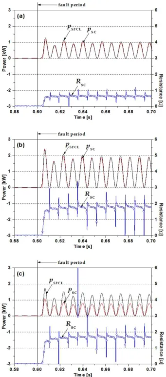
Fig. 6. Power burdens of both the SFCL and the HTSC module, and the resistance of HTSC module with either magnetic flux application circuit or not during fault period. (a) in case that magnetic flux application circuit was not installed (RP=0.76 Ω), (b) in case that magnetic flux application circuit was not I installed (RP=2.30 Ω), and (c) in case that magnetic flux application circuit was installed (RP=2.30 Ω).
회로를 적용하지 않고 초전도모듈의 저항이 증가하지 않은 경우 한류기에 유기전압(vN1w/o,Rp=0.707)이 가장 작 게 발생하였으며, 제한되는 고장전류는 자계인가회로를 적용하지 않고 직렬로 초전도모듈을 연결하여 저항증 가를 모의한 경우(vN1w/o,Rp=2.3)가 다른 경우보다 고장전 류크기가 작게 제한되는 것을 비교할 수 있다.
그림 5는 그림 3에서 검토한 세 가지 경우에 대해 고장발생시 자속구속형 초전도한류기를 구성하는 초전 도모듈에 유기되는 전압(vSC)과 초전도모듈의 전류(iSC) 파형을 비교하여 도시하였다. 그림 5에서 보는 것처럼, 자속구속형 초전도한류기를 구성하는 초전도모듈에 유 기되는 세 가지 경우의 전압은 그림 4에서 분석한 초 전도한류기 전체전압에서와 유사하게 차이를 보였으며, 초전도모듈의 전류는 그림 4에서 분석한 초전도한류기 에 의해 제한되는 전류와 달리 세 가지 경우에서 편차 가 크게 발생되는 것을 비교할 수 있다. 또한, 자계인 가회로를 설치하여 초전도모듈의 저항을 증가시킨 경 우에 초전도모듈의 전류(iSCRp=2.3)가 가장 작게 흐르는 것을 분석할 수 있다.
마지막으로 그림 6은 그림 4와 그림 5에서 검토한 세 가지 경우의 초전도한류기의 전력부담(pSFCL)과 초 전도한류기를 구성하는 초전도모듈의 전력부담(pSC)을 나타내었다. 자계인가회로를 설치하지 않은 경우에는 고장 발생 기간 동안 초전도한류기의 전력 부담과 초 전도모듈의 부담이 유사하게 발생하는 것을 볼 수 있 으며, 초전도모듈의 직렬연결을 통해 저항을 증가시킬 경우 전체 부담도 증가되는 것을 그림 6(a)와 그림
6(b)에서 비교분석할 수 있다. 반면에, 자계인가회로를 설치한 경우에는 초전도한류기의 전력 부담보다 초전 도모듈의 부담이 차지하는 비율이 작아지는 것을 그림 6(c)에서 확인할 수 있다.
위의 결과들을 통해서, 자계인가회로를 이용하여 자 속구속형 초전도한류기의 초전도모듈의 저항을 증가시 켜 고장전류를 제한할 경우, 고장전류제한측면에서는 불리할 수 있지만, 초전도한류기를 구성하는 초전도모 듈의 전력부담측면에서는 유리하다는 결과를 얻을 수 있었다.
4. 결 론
자속구속형 초전도한류기의 자계인가회로 설치에 따른 한류기 동작 특성의 개선 유무에 대한 검토가 필요하며, 본 논문에서는 이에 대한 유용성 검증을 위해 자계인가회로 존재 유무에 따른 자속구속형 초 전도한류기의 고장전류 제한 효과와 한류기를 구성하 는 초전도모듈의 부담에 대해 모의 실험 결과를 통해 비교분석하였다. 자계인가회로를 이용하여 자속구속 형 초전도한류기의 초전도모듈의 저항을 증가시켜 고 장전류를 제한할 경우, 고장전류 제한 측면에서는 불 리할 수 있지만, 초전도한류기를 구성하는 초전도모 듈의 전력 부담 측면에서는 유리함을 모의 실험을 통 해 얻은 고장전류와 전력 부담에 대한 비교 분석을 통해 확인할 수 있었다.
REFERENCES
[1] E. Thuries, V. D. Pham, Y. Laumond, U. Verhaege, A, Fevrier, M. Collet, and M. Bekhaled, IEEE Trans. On Power Del., 6, 2 (1991). [DOI: http://dx.doi.org/10.1109/61.131138]
[2] H. Kado and M. Ichikawa, IEEE Trans. on Appl. Supercond., 7, 2 (1997). [DOI: http://dx.doi.org/10.1109/77.614672]
[3] B. Gromoll, G. Ries, W. Schmidt, H. P. Kramer, and H. W.
Neumuller, IEEE Trans. on Appl. Supercond., 7, 2 (1997).
[DOI: http://dx.doi.org/10.1109/77.614631]
[4] H. Yamaguchi, T. Kataoka, K. Yaguchi, S. Fujita, K.
Yoshikawa, and K. Kaiho, IEEE. Trans. Appl. Supercond., 14, 2 (2004). [DOI: http://dx.doi.org/10.1109/TASC.2004.840820]
[5] H. Shimizu, Y. Yokomizu, T. Matsumura, and N.
Murayama, IEEE Trans. Appl. Supercond., 12, 1 (2002).
[DOI: http://dx.doi.org/10.1109/TASC.2002.1018344]
[6] M. Ichikawa, H. Kado, M. Shibuya, M. Kojima, M. Kawahara, and T. Matsumura, IEEE Trans. on Appl. Supercond., 13, 2 (2003).
[7] A. Hekmati, M. Hosseini, M. Vakilian, and M. Fardmanesh, Physica C, 472, 39 (2012). [DOI: http://dx.doi.org/10.1016/j.
physc.2011.10.007]
[8] S. H. Lim, IEEE Trans. Appl. Supercond., 17, 2 (2007).
http://dx.doi.org/10.1109/TASC.2007.903960]
[9] S. H. Lim and H. S. Choi, Physica C, 445, 1073 (2006). [DOI:
https://doi.org/10.1016/j.physc.2006.05.027]
[10] S. H. Lim, J. F. Moon, and J. C. Kim, IEEE Trans. on Appl.
Supercond., 19, 3 (2009). [DOI: https://doi.org/10.1109/TASC.
2009.2018053]
[11] S. H. Lim, S. Ko, and T. H. Han, Physica C, 484, 253 (2013).
[DOI: https://doi.org/10.1016/j.physc.2012.03.011]
[12] S. C. Ko, T. H. Han, and S. H. Lim, Physics Procedia, 45, 305 (2013). [DOI: https://doi.org/10.1016/j.phpro.2013.05.028]