Regular Paper
1000
J. KIEEMEVol. 25, No. 12, pp. 1000-1003, December 2012 DOI: http://dx.doi.org/10.4313/JKEM.2012.25.12.1000
변압기 권선을 이용한 자속구속형 초전도 전류제한기의 전류제한 및 전압강하 보상 특성
고석철1,a
1 공주대학교 산학협력단
Current Limiting and Voltage Sag Compensation Characteristics of Flux-Lock Type SFCL Using a Transformer Winding
Seok-Cheol Ko
1,a1 Industry-University Cooperation Foundation, Kongju National University, Gongju 314-701, Korea
(Received October 15, 2012; Revised November 12, 2012; Accepted November 19, 2012)
Abstract: The superconducting fault current limiter (SFCL) can quickly limit the fault current shortly after the short circuit occurs and recover the superconducting state after the fault removes and plays a role in compensating the voltage sag of the sound feeder adjacent to the fault feeder as well as the fault current limiting operation of the fault feeder. Especially, the flux-lock type SFCL with an isolated transformer, which consists of two parallel connected coils on an iron core and the isolated transformer connected in series with one of two coils, has different voltage sag compensating and current limiting characteristics due to the winding direction and the inductance ratio of two coils. The current limiting and the voltage sag compensating characteristics of a SFCL using a transformer winding were analyzed.
Through the analysis on the short-circuit tests results considering the winding direction of two coils, the SFCL designed with the additive polarity winding has shown the higher limited fault current than the SFCL designed with the subtractive polarity winding. It could be confirmed that the higher fault current limitation of the SFCL could be contributed to the higher load voltage sag compensation.
Keywords: Flux-lock type superconducting fault current limiter (SFCL), Voltage sag compensating characteristics, Isolated transformer
1. 서 론1)
전력공급설비의 증가는 전력계통의 복잡화와 송전
a. Corresponding author; [email protected]
Copyright ©2012 KIEEME. All rights reserved.This is an Open-Access article distributed under the terms of the Creative Commons Attribution Non-Commercial License (http://creativecommons.org/licenses/by-nc/3.0) which permits unrestricted non-commercial use, distribution, and reproduction in any medium, provided the original work is properly cited.
용량의 증가를 발생시켜 왔으며, 이로 인해 단락발생 시 고장전류가 기존 차단기의 단략 용량을 초과하는 전력계통 내 구간 개수가 증가되고 있다. 이와 같은 고장전류에 대한 대안으로 차단 내력이 큰 차단기의 교체나 고 임피던스 전력설비 또는 직렬 리액터 설 치, 연계 선로의 분리 운전 등을 제안하고 있으나, 경 제적, 기술적, 계통 안정도 면에서 해결해야 할 문제 점들이 남아 있다 [1]. 이를 해결하기 위한 대안으로 초전도 고유 특성을 이용한 초전도 전류제한기가 가
전기전자재료학회논문지, 제25권 제12호 pp. 1000-1003, 2012년 12월: 고석철 1001
Fig. 1. Structure of a flux-lock type SFCL with parallel connected two coils using a transformer winding.
장 이상적인 요구조건에 근접한 특성을 보유하고 있 다고 평가됨에 따라 고장전류 저감을 위한 신개념의 대안으로 주목받아, 실계통에 적용하고자 하는 노력 들이 활발하게 진행되고 있다 [2-4]. 초전도 전류제한 기를 실계통에 적용하기 위해서는 전류제한기를 구성 하는 초전도 소자의 전력 부담을 감소시켜야 하며, 이 를 위한 연구들이 진행되어 왔으며 그 중에서도 코일 의 자기결합을 이용한 초전도 전류제한기 모델들이 제안되어 왔다 [5-9]. 또한, 핵심소자인 초전도 소자 의 직접적인 고장전류 도통을 피하고 전력부담을 감 소시키기 위해 변압기 권선을 통해 분리․연결시킨 구조의 내부 전류제한 특성들을 비교 분석한 기존 논 문들이 보고된 바 있다 [11].
본 논문에서는 기존까지 보고되지 않은 초전도 소 자의 직접적인 전력 부담을 줄이기 위해 변압기 권선 을 이용한 초전도 전류제한기의 모의단락 실험을 통 해 선로 고장 시 건전상 선로의 부하전압 강하 보상 특성에 미치는 영향을 고찰하고자 하였다. 이를 위해 먼저, 모의계통 선로를 구성하였으며, 피더단에 변압 기 권선을 이용한 초전도 전류제한기를 적용한 경우 제한기를 구성하는 두 코일의 권선 방향에 따른 고장 전류제한 및 부하전압 강하 보상 특성을 분석하였다.
분석을 통해 고장전류 제한율과 부하전압 강하율의 변화를 비교 분석하였다.
2. 실험 방법
그림 1은 병렬 연결된 두 코일과, 두 코일 중 하나
Fig. 2. Experimental circuit of a flux-lock type SFCL using a transformer winding.
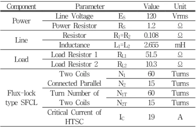
Table 1. Specification of experimental circuit with a flux-lock type SFCL.
Component Parameter Value Unit
Power Line Voltage E
S120 Vrms
Power Resistor R
S1.2 Ω
Line Resistor R
1=R
20.108 Ω
Inductance L
1=L
22.655 mH
Load Load Resistor 1 R
L151.5 Ω
Load Resistor 2 R
L210.3 Ω
Flux-lock type SFCL
Two Coils Connected Parallel
N
160 Turns
N
215 Turns
Turn Number of Two Coils
N
1T60 Turns
N
2T15 Turns
Critical Current of
HTSC I
C19 A
의 직렬 연결되는 초전도 소자를 별도의 변압기 권선 을 이용하여 연결함으로써 고장전류 경로로부터 분리 가 가능한 자속구속형 초전도 전류제한기를 구성하였 다. 이와 같이 구성된 변압기 권선을 이용하여 자속 구속형 초전도 전류제한기의 고장전류 제한 특성 분 석을 위한 모의단락 회로를 구성하여 모의단락 실험 을 실시하였으며, 실험 장치의 구성 요소와 각 파라 미터를 표 1에 나타내었다.
그림 2는 단락사고를 모의하기 위해 스위치 SW1을 투입한 후 SW2를 주어진 고장주기 5주기 동안 투입 하여 단락을 모의하였다. 모의한 5주기 동안 변압기 권선 및 초전도 소자를 비롯하여 자속구속형 초전도 전류제한기를 구성하는 각 권선에 유기되는 전압과 전류를 측정하여 전류 제한 및 회복 특성을 분석하였 다.
1002 J. KIEEME, Vol. 25, No. 12, pp. 1000-1003, December 2012: S.-C. Ko
3. 결과 및 고찰
그림 3은 초전도 전류제한기가 설치되어 있지 않은 모의 실험계통에 고장이 발생할 경우, 각 피더전류 (
,
)와 부하전압 (
,
)을 각각 보여준 다. 고장발생 동안 고장난 피더에서 고장전류 증가와 건전피더와 부하전압이 저하되는 것을 확인할 수 있 다. 초전도 소자의 부담을 줄이기 위해 절연변압기 권선을 사용한 초전도 전류제한기를 설치할 경우 두 코일의 결선방향에 따른 고장전류 제한 및 건전상의 부하전압보상 특성을 그림 4와 5에 각각 도시하였다.Fig. 3. Load voltage and fault current waveforms in a system without SFCL.
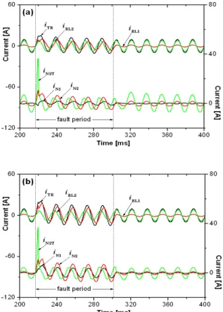
그림 4는 가극결선한 경우, 코일 1의 전류 (
)가 반전 되어 흐르는 것을 확인할 수 있으며, 고장 발생 초기 고장 전류의 피크 (
)가 감극결선한 경우보다 작게 발생되는 것을 비교할 수 있다. 이는 동일한 설계 조건에서 가극결 선한 경우, 제한기 동작전류가 감극결선한 경우보다 작게 발생되는 기존의 연구 결과와 일치한다 [8]. 고장주기 동안 에 초전도 소자로 도통되는 전류 (
)는 권선 방향에 관계없이 비슷한 크기로 제한되는 것을 볼 수 있다.고장발생 동안 부하전압에서는 건전상 부하전압 (
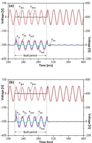
)이 보상되어 고장 전의 전압을 유지하고 있는 것을 그림 5에서 확인할 수 있다. 특히, 감극결선한 경우 고장발생 후 반주기가 지난 후부터 고장 전의 전압 크기보다 약간 작은 값으로 보상이 되는 것을 볼 수 있다. 각 코일과 초전도 소자에 유기되는 전압에 서는 초전도 소자에 유기되는 전압 (
)이 권선 방향 에 관계없이 거의 같은 크기로 발생되는 것을 확인할Fig. 4. Fault current limiting characteristics of a flux-lock type SFCL using a transformer winding. (a) the additive polarity winding, (b) the subtractive polarity winding.
수 있다. 고장기간 동안에 변압기 권선을 이용한 초전도 전류제한기를 구성하는 초전도 소자의 부담을 감소시킬 수 있음을 확인할 수 있다. 고장제거 시 초전도 전류제한 기의 회복 특성에서도 가극결선이나 감극결선 시 거의 비 슷한 회복 시간을 갖는 것을 그림 5에서 비교할 수 있다.
그림 6은 초전도 소자에 변압기 권선을 연결한 구 조의 초전도 전류제한기의 결선 방향에 따른 고장 전 류제한율 (
∆
)과 건전피더의 부하전압의 변동률 (∆
)을 보여준다. 고장전류의 제한율과 부하전압 변동률은 식 (1)과 (2)와 같이 계산하여 도시하였다.∆
×
(1)
∆
×
(2)전기전자재료학회논문지, 제25권 제12호 pp. 1000-1003, 2012년 12월: 고석철 1003
Fig. 5. Voltage sag compensating characteristics of a flux-lock type SFCL using a transformer winding. (a) the additive polarity winding, (b) the subtractive polarity winding.
Fig. 6. Variation of load voltage sag and current limiting rates of a flux-lock type SFCL using a transformer winding during a fault period.
앞의 전류제한 및 전압강하 보상 특성에서 분석한 것과 같이 가극결선한 경우가 고장전류 제한과 부하 전압 보상효과가 감극 결선한 것보다 크게 기여하는 것을 확인할 수 있었다.
4. 결 론
본 논문에서는 변압기 권선을 이용한 초전도 전류 제한기의 계통 적용에 따른 영향을 모의실험을 통해 분석하였다. 분석을 위해 초전도 전류제한기를 모의 계통선로의 피더 앞 단에 설치하였으며, 피더단에 변 압기 권선을 이용한 초전도 전류제한기를 적용할 경 우, 제한기를 구성하는 두 코일의 권선방향에 따른 고장전류제한 및 부하전압 강하 보상특성을 분석하였 다. 분석을 통해 가극결선한 경우가 고장전류제한율 과 부하전압 강하율의 변화가 감극 결선한 경우보다 훨씬 더 향상됨을 비교할 수 있었다.
REFERENCES