Journal of the Korea Institute for Structural Maintenance and Inspection Vol. 17, No. 2, March 2013, pp.083-093
http://dx.doi.org/10.11112/jksmi.2013.17.2.083
pISSN 2234-6937 eISSN 2287-6979
기초침하에 의해 손상된 송전철탑 구조물의 구조성능개선
Structural Restoration for the Electric Power Transmission Tower Damaged by Foundation Settlements
이 호 범1)* 박 종 권2) 김 일 수3) 장 일 영4) 송 재 호5)
Lee, Ho Beom Park, Jong Kwon Kim, Il Soo Jang, Il Young Song, Jae Ho
Abstract
Generally the capacities of electric power transmission tower’s members are improved by increasing their stiffness nature through injection of grout or attachment of other structural stiffeners. Those are for upgrading their axial strength by fulfillment of proper materials into pipe members, increment of member dimension by addition of section, or a combination of the two. However the use of innovative and unusual procedures would be positively recommended for getting more stable state. It is that buckled members are replaced with lengthened and strengthened members. In providing the structural restoration procedures for the existing electric power transform tower whose main members have been damaged due to unequal foundation settlement, structural damage inspection works and numerical analyses for the damaged one and the restored one were done in detail at first. secondarily member-exchanging works using a newly-generated jacking system and strengthened members were achieved. This figures are to point clearly to inherent advantages attending the management of the towers.
Keywords : Electric power transmission tower, Structural safety inspection, Jacking system, Strengthening existing member
1) 정회원, (주)쓰리텍 대표이사, 교신저자 2) 정회원, 국토해양부 건설수자원정책실 과장 3) 정회원, (주)대우건설 토목사업본부 부장 4) 정회원, 금오공과대학교 토목공학과 교수 5) 정회원, 금오공과대학교 토목공학과 교수
* Corresponding author : [email protected]
• 본 논문에 대한 토의를 2013년 4월 30일까지 학회로 보내주시면 2013년 5월호에 토론결과를 게재하겠습니다.
Copyright Ⓒ 2012 by The Korea Institute for Structural Maintenance and Inspection. This is an Open Access article distributed under the terms of the Creative Commons Attribution Non-Commercial License (http://creativecommons.org/licenses/by-nc/3.0)which permits unrestricted non-commercial use, distribution, and reproduction in any medium, provided the original work is properly cited.
1. 서 론
해상 구조물은 장수명 수동형 구조물로서 내구연한 기간 동안의 구조적 안전성과 건전성이 확보되어야 한다. 따라서 구조 부재들이 위해적 환경 하에 존속하더라도 과다 변형이 야기되거나, 손상에 의한 부적절한 상태가 되지 말아야 하고, 손상이 발생될 경우 성능개선에 따른 건전성을 회복시켜야 한다. 본 실증적 연구는 구조적 이상 현상이 발생된 하나의 송전철탑 일부 사재들의 손상을 보다 기술적으로 안전성을 회복시키는 전반 보강 방안을 현실화하는 절차를 다루게 된 다. 즉, 대부분의 기존 구조적 보수 또는 보강 방식은 부재가 손상된 상태에서의 변형 형태를 그대로 유지한 채로 대책을 강구한다. 이는 외란 또는 지반침하 등의 위해적 요인에 의 해 추가 손상이 발생할 경우, 구조 안전성 훼손이 가속화 된
다. 본 논문에서는 이러한 문제를 제거할 수 있도록 기 손상 된 송전철탑 부재의 탄성적 원상 회복을 위한 새로운 기법을 고안하여 실적용하면서 구조 거동을 분석하였고, 그 결과의 효율성을 입증하였다.
2. 구조물 현황 및 보강 프로세스
2.1 구조물 현황과 분석방향본 구조물은 준공 후 일정 시간이 지난 후 4개 독립기초에 침하 (D각 지반기초 68mm 부등침하 발생)가 발생되어 대책 강구 결과에 따른 보수 및 보강 공사를 하였다. 공사는 기초 를 원위치로 회복하지 않고, 각 부재에 에너지 소산에 따른 잔류응력을 그대로 유지한 상태에서 이상 현상이 발생된 강
Table 1 Process of structural restoration
items contents
field work reviewing variations over diagonal members, examining the method of field work, checking the way of supports usage required for replacement work
numerical analysis and fabrication of supports
structural analyses for diagonal members, fabricating supports (factory/site) and jacking-up devices, carrying in and applying field materials
fabrication of diagonal members importing diagonal members, grouting, and curing concrete in diagonal members, carrying in diagonal members and measuring the length
surveying / measurement and replacement / reinforcement of members
replacing members, filling diagonal members with concrete, surveying and measuring structure while replacing, painting and inspecting members, dismantling and withdrawal of site facilities, and cleaning up the site
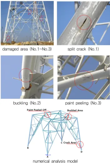
damaged area (No.1~No.3) split crack (No.1)
buckling (No.2) paint peeling (No.3)
numerical analysis model Fig. 1 Structural damage aspects on situ
관형 사재 내부에 보강재 (시멘트 몰탈)를 주입하여 강성 및축력 저항 능력을 증대시켰다. 그러나 2년 후 일부 사재에서 구조적 파괴 및 이상 현상과 과거 보강 공사 후 D각 기초 추 가 침하 12mm가 발생되었음이 재차 확인되었다. 손상 현상 은 C-D면 D각 사재 하단에 사재 길이 방향으로 할열 파괴 균열 생성, C-D면 C각 사재 상단의 좌굴 발생, B-C면 C각 사재 상단 도막 벗겨짐 현상 발생 등이다. 본 연구에서는 이 들 사재의 보수 및 보강에 따른 구조 성능 개선이 원활히 이 루어지도록 다각도 수치해석을 통해 새롭게 창안한 탄성 회 복용 support 시스템 개발, 사재 교체시 발생될 위험 요인 해 소, 대상 부재에서의 응력 및 변위 등의 사전 분석・검토에 따라 보강 정밀성을 확립하였다. 또한 보강 작업시 정밀 측 량 및 계측을 통해 부재의 구조적 변화를 정확히 판단하여 보다 안전하고 효율적인 결과를 도출토록 하였다.
2.2 보강대상 구조물 조사
Fig. 1과 같이 보강 대상 구조물의 균열, 만곡, 도장훼손 등의 현황 조사를 수행하였고, 그 결과는 시스템 해석을 위 한 모델링에서의 위치와 일치시켰다.
2.3 보강 프로세스
보강 프로세스는 부재 교체 수행 순서에 따른 전반적 계획 을 수립하고, 보강 방안 상세에 따라 엔지니어링 분석, 현장 보강 작업 상세, 보강 작업시의 측량 및 계측, 보강 작업장의 해체 및 철수 등의 작업을 수행하였다. 특기 사항은 콘크리 트로 보강되고, 최적의 길이로 늘린 새 부재가 효율적으로 교체되기 위해 support 및 잭업 장치가 새롭게 고안되었고, 손상된 사재가 제거된 부재 교체 영역에 역 변위가 발생되도 록 유도한 것이다. 보강 단계 과정은 Table 1과 같고, 보강 상세는 Table 2와 같다.
3. 기초침하에 따른 해석적 고찰
3.1 구조해석 제한 및 조건송전철탑의 기초 침하에 따른 해석적 고찰의 해석조건은 고온계 상시일 때에 대해 분석하였고, 설계시의 하중 조건 (풍하중, 송전선 하중)을 적용하였으며, 풍속은 설계 기본 풍 속 36.6 m/sec을, 기초 침하에 대해서는 측량에 의한 기초
Table 2 Contents and processes for structural safety inspections
items inspection contents
engineering work
axial resistant force ① estimating changes of axial force and displacement in members while removing and replacing
② calculating jacking-up force according to growth of reversed displacement
structural safety of support
① examining slenderness ratio of support
② calculating allowable buckling stress and force
③ inspecting member capacity of support while removing damaged members
④ readjusting jacking force according to reanalyses numerical analysis while
replacing
① analysing structures numerically for control of jacking-up forces according to results of continuous measurement while replacing members
reinforcement by replacing the members
jacking-up ① conducting jacking-up for a smooth separation of the bolts and nuts
② measuring initial diplacements and strains while jacking-up
replacing work
① separating bolts and nuts
② dismantling damaged members
③ filling old diagonal members with concrete
④ lifting new members and fastening bolts partially
⑤ jacking-up
⑥ fastening bolts completely in accordance with regulations of the standard for the torque painting process ① applying primer coat paint epoxy (bonding)
② applying topcoat paint : urethane (color painting) measurement while
replacing
surveying / measurement (vertical displacement)
① setting up data loggers and survey instrument
② checking measurement systems and measuring test signals
③ surveying and measuring behavior of members while replacing
dismantling and withdrawal
dismantling and painting / repair
① removing and dismantling scaffolds
② dismantling jack-up system
③ dismantling stands and jigs
④ painting members
⑤ carrying out silicone- waterproof work on the top of diagonal members
⑥ dismantling scaffolds
⑦ cleaning up the site
Table 3 Requirements for numerical analysis
items contents
specifications
voltage 345kV
No. of transmission wires 2 CCT
types SA2
load span vertical 700 m
horizontal 900 m
track horizontal angle 3°
unit wind load
unit wind load on tower
shape steel high : 575 kgf/m
2steel pipe high : 322 kgf/m
2unit wind load on arms high : 522 kgf/m
2unit wind load on insulator high : 674 kgf/m
2region pyrometer region 2
cryometer the other regions
strung wire
overhead ground wire maximum working tension : 5700 kg transmission wire maximum working
tension : 6000 kg
insulator weight : 900 kg/set
indication sphere weight : 8 kg/ea unit wind load
on strung wire
overhead ground wire high : 121 kgf/m
2transmission wire high : 109 kgf/m
2unit wind load on indication sphere high : 84 kgf/m
2dead loads G.W : 300kg,
CONC : 400kg
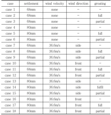
Table 4 Cases of sensitivity analysis
case settlement wind velocity wind direction grouting
case 1 68mm none - -
case 2 68mm none - full
case 3 68mm none - partial
case 4 80mm none - -
case 5 80mm none - full
case 6 80mm none - partial
case 7 68mm 36.6m/s side -
case 8 68mm 36.6m/s side full
case 9 68mm 36.6m/s side partial
case 10 68mm 36.6m/s front -
case 11 68mm 36.6m/s front full
case 12 68mm 36.6m/s front partial
case 13 80mm 36.6m/s side -
case 14 80mm 36.6m/s side fulfil
case 15 80mm 36.6m/s side partial
case 16 80mm 36.6m/s front -
case 17 80mm 36.6m/s front full
case 18 80mm 36.6m/s front partial
Considerations in modeling :
1) usual state in pyrometer 2) tension of transmission wire
3) settlement of Dposition 4) basic design wind velocity
5) wind direction : front (arm direction), side (perpendicular to arm direction)
overall structure diagonal members of responses
positions of over-stress
Fig. 2 Structural modelling and stress response (diagonal member)
redundant members of responses
positions of over-stress
Fig. 3 Structural modelling and stress response (horizontal member)
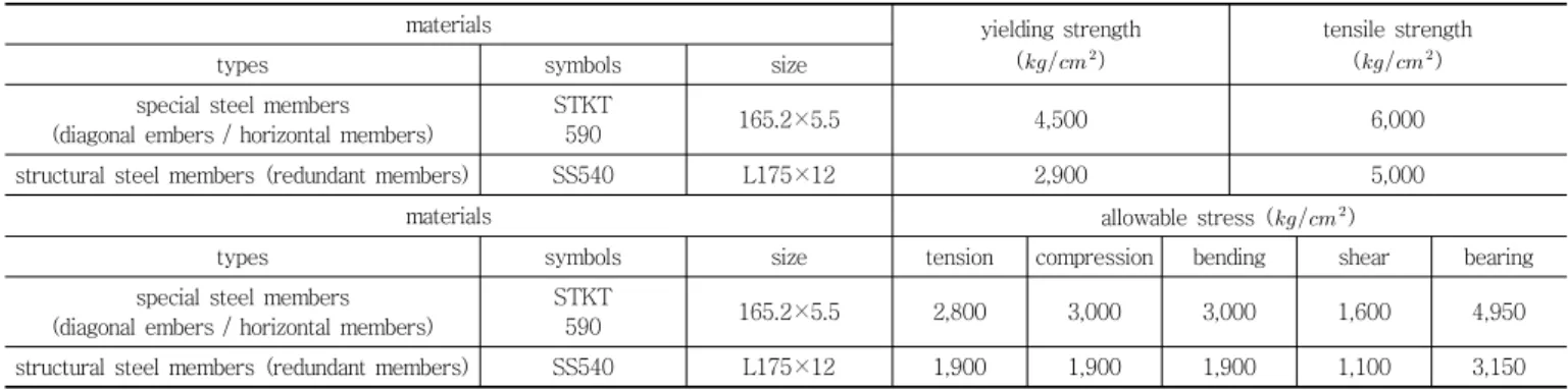
Table 5 Characteristics of steel members
materials yielding strength
(
)
tensile strength (
)
types symbols size
special steel members (diagonal embers / horizontal members)
STKT
590 165.2×5.5 4,500 6,000
structural steel members (redundant members) SS540 L175×12 2,900 5,000
materials allowable stress (
)
types symbols size tension compression bending shear bearing
special steel members (diagonal embers / horizontal members)
STKT
590 165.2×5.5 2,800 3,000 3,000 1,600 4,950
structural steel members (redundant members) SS540 L175×12 1,900 1,900 1,900 1,100 3,150
침하 실측 자료를 적용하였다. 기타 송전철탑과 관련된 기하 형상 및 고정 하중 등과 관련된 수치 해석 조건은 Table 3과 같고, 기초 침하량, 풍하중 방향 및 그라우팅 정도 조건 등에 대한 예민도 해석의 경우 수는 Table 4와 같다. 또한 Fig. 2 와 Fig. 3에서는 각각 사재 및 수평재 모델링과 그 수치해석 결과인 부재 응력을, Table 5에서는 관련된 부재들의 제원을
나타내었다.
3.2 구조해석 결과
수치 해석 결과로부터 도출된 각 부재의 응력은 허용 응력 값과 비교하였다. 허용응력은 두 가지 형태로 검토하였는데,
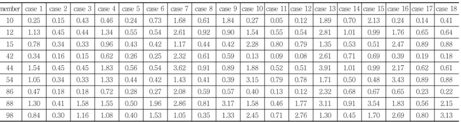
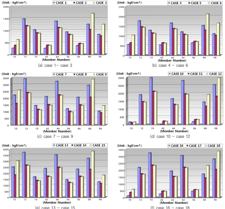
Table 6 Case’s values of stress combination for diagonal members
member case 1 case 2 case 3 case 4 case 5 case 6 case 7 case 8 case 9 case 10 case 11 case 12 case 13 case 14 case 15 case 16 case 17 case 18 10 0.25 0.15 0.43 0.46 0.24 0.73 1.68 0.61 1.84 0.27 0.05 0.12 1.89 0.70 2.13 0.24 0.14 0.41 12 1.13 0.45 0.44 1.34 0.55 0.54 2.61 0.92 0.90 1.54 0.55 0.54 2.81 1.01 0.99 1.76 0.65 0.64 15 0.78 0.34 0.33 0.96 0.43 0.42 1.17 0.44 0.42 2.28 0.80 0.79 1.35 0.53 0.51 2.47 0.89 0.88 42 0.34 0.16 0.15 0.62 0.26 0.25 2.32 0.61 0.59 0.13 0.09 0.08 2.61 0.71 0.69 0.39 0.19 0.18 44 1.54 0.45 0.45 1.83 0.56 0.54 3.62 0.91 0.89 1.88 0.52 0.51 3.91 1.01 0.99 2.17 0.62 0.61 54 1.05 0.34 0.33 1.33 0.44 0.42 1.43 0.41 0.39 3.15 0.79 0.78 1.71 0.50 0.48 3.43 0.89 0.88 86 0.47 0.18 0.18 0.72 0.28 0.27 2.08 0.59 0.57 0.40 0.13 0.12 2.32 0.68 0.67 0.65 0.23 0.22 88 1.30 0.41 1.58 1.55 0.50 1.96 2.86 0.81 3.17 1.58 0.46 1.77 3.11 0.91 3.54 1.83 0.56 2.15 98 0.84 0.30 1.16 1.08 0.40 1.53 1.05 0.35 1.33 2.45 0.71 2.76 1.30 0.45 1.70 2.69 0.80 3.13 note : 1) member 10 (split crack) 2) member 88 (buckling) 3) member 98 (paint peeling)
하나는 부재들에 대한 조합응력 허용 상관식, 식 (1)에 의한 것이고, 다른 하나는 한전설계기준 허용 좌굴 응력식, 식 (2) 에 의해 검토하였다.
조합응력 허용 상관식 :
≤ (1)
여기서, : 축방향 압축응력
: y축 휨 압축응력
: z축 휨 압축응력
: 허용축방향 압축응력
: y축 허용휨 압축응력
: z축 허용휨 압축응력
세장비 ( )에 따른
허용좌굴응력도 산출식 : ①, ② (2)
① ≥ 100 일 경우
허용좌굴응력 ()=
② 0 < <100 일 경우
허용좌굴응력 ()=
여기서 : =0시 허용좌굴응력 ()
,, : 재질, 단면형상, 구조에 의한 계수
송전철탑 주주재 위치인 D각과 C각에서의 사재부재와 주 변 보조재 (수평재, 대변보조재)에 대해 Table 4의 예민도 분 석과 관련된 경우 수별 해석 결과는 Table 6, Fig. 4, Table
7~8과 같다. 표에서 볼드체는 조합 응력비 1.0을 초과한 값 을 의미한다.
사재에 대한 해석적 고찰에서 CASE 2, 5, 8, 11, 14, 17의 경우 조합 응력비가 양호하다. CASE 1, 4, 7, 10, 13, 16은 충전재 없이 강관만을 사용한 경우이고, 기 손상된 위치의 부재에서 과다 응력이 도출되고 있는 것은 기초 침하시의 송 전철탑 구조계에 대한 응력 해석이 매우 의미 있음을 확인하 게 된다. 주변 보조재는 기초 침하에 따라 과다 응력 발생하 여 좌굴되는 경우가 많다. D각의 80mm 기초 침하 및 풍하 중 고려시 많은 부재가 조합 응력비 1.0을 다소 초과하고 있 다. 본 구조물은 추가 안전율이 고려된 구조체로 평가되므로 확연한 이상 현상은 없으나, 구조적 안전성에 문제가 야기될 수 있음을 경고한다.
4. 보강에 대한 실증적 고찰
4.1 Support-유압잭 거치에 따른 거동해석
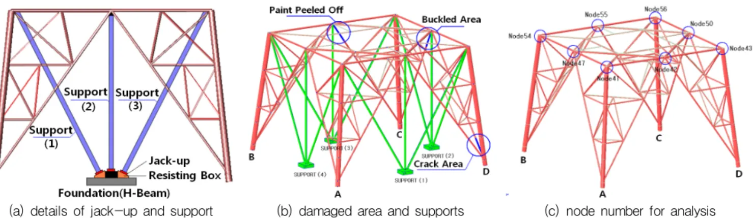
Support 유압잭 력을 이용한 사재 교체시 사전해석을 통해 구조적 기능을 보완할 수 있도록 약간 길게 제작된 신사재의 길이 방향 공간 확보가 중요하다. 따라서 각 부재에의 변위 량 및 하중부하 정도를 사전에 해석적으로 평가하고, 구사재 존속 상태에서 support 시험 잭업 작업시 계측 결과를 분석 한 다음 사재 교체 작업에 사용하는 support 유압잭 력을 현 실성 있게 조정하였다. 잭업 support 시스템은 송전철탑 A-B 면, B-C면, C-D면, D-A면 등 4면에 설치하였다. 구조 거동 예민도는 경우 수에 따른 유압잭 력 변화와 이에 대한 대상 위치에서의 구조 변화를 해석적으로 평가하였다. 여기서 풍 하중 및 D각의 기초 침하 상태는 고려하지 않았다. Fig. 5 및 Table 9는 support, 수치 해석 결과 정보를 도시하였다.
(a) case 1~ case 3 (b) case 4 ~ case 6
(c) case 7 ~ case 9 (d) case 10 ~ case 12
(e) case 13 ~ case 15 (f) case 16 ~ case 18
note : no. of member is on the abscissa, stress value is on the ordinate. bar chart is representative of the case results Fig. 4 Case’s values of axial direction stress for damaged members
Table 7 Case’s values of stress combination for horizontal members (-59 m from the top)
no. of member 104 105 110 111 114 115 120 121 steel type SS540 (redundant member)
case 15 1.27 1.45 0.95 1.37 0.93 1.43 0.85 1.11 case 18 1.14 1.12 1.15 1.03 1.33 1.30 1.25 1.31 no. of member 101 102 107 109 116 118 123 124
steel type STKT590 (horizontal member)
case 15 0.46 0.33 0.29 1.11 0.52 0.38 0.44 0.40 case 18 0.36 0.46 0.53 1.05 0.45 0.98 0.52 0.43
Table 8 Case’s values of stress combination for horizontal members (-49 m from the top)
no. of member 180 181 186 187 190 191 196 197 steel type SS540 (redundant member)
case 15 0.71 0.92 0.62 1.16 0.63 1.21 0.86 1.11 case 18 0.56 0.58 0.78 0.81 0.99 1.05 1.23 1.27
4.2 Support 구조 안전성 평가
Support는 유압잭 력을 송전철탑 구조체에 직접 전달하여
(a) details of jack-up and support (b) damaged area and supports (c) node number for analysis Fig. 5 Support position and target node numbers in numerical analysis
Table 9 Case’s values for member displacement changes
(except wind load) (unit : mm)
node case 1 case 2 case 3 case 4 case 5 case 6
43 0.893 1.795 2.692 2.769 2.512 1.218
42 1.37 2.741 4.111 0.239 1.644 1.27
41 0.899 1.797 2.696 -0.238 2.513 0.569
47 1.375 2.749 4.124 -0.308 1.649 1.252
54 0.902 1.804 2.706 -0.344 2.518 2.191
55 1.434 2.868 4.302 0.032 1.718 1.727
56 0.892 1.785 2.678 1.54 2.507 2.841
50 1.491 2.981 4.472 1.966 1.789 1.893
remark
case1-10tonf jacking-up for all, case2-20tonf jacking-up for all, case3-30tonf jacking-up for all case4-30tonf jacking-up to inclined supports, 10tonf jacking-up to vertical supports on C-D face, case5-30tonf jacking-up to all of inclined supports, 10tonf jacking-up to all of vertical supports, case6-30tonf jacking-up to inclined supports, 10tonf jacking-up to vertical supports on C-D face, and 10tonf jacking-up for all on A-B, B-C, and A-D faces
Table 10 Characteristics for support member
materials yield strength
(
)
tensile strength
(
) size area
(
)
unit weight/unit length (
) types of steel symbol
carbon steel pipes SPPS42 2,500 4,200 ø165.2×t11 53.29 41.8
materials radius of gyration (
)
effective length (
)
slenderness ratio (
)
allowable axial stress (
)
allowable buckling load (
) types of steel symbol
carbon steel pipes SPPS42 5.46 550 100.73 936 49,879
1,000 183.15 284 15,134
note : 1) slenderness ratio (
)≥ 100, allowable axial stress (
)=
, allowable buckling load (
)=
×
2) effective length of inclined support (total length=1,100cm, restraint on center) : 550cm
손상된 부재의 탄성 회복 길이를 최대한 확보케 하는 보조 구조물로서 보강 작업시 좌굴 손상이 야기되면 안 된다. 따 라서 한전설계기준-1111 (가공송전용 철탑설계기준)에 따른 support 부재의 좌굴안전성 검토를 수행하여 경사 support는
최대 30 tonf, 수직 support는 10tonf의 하중을 가해도 문제 가 발생되지 않도록 하였다. 특히 연결부 강성화 확보를 위 해 4면에 22mm 철판으로 강성 보강하므로써 support 축방 향 허용 압축 하중을 충분히 유지토록 하였고, 사재 교체 당 시 구사재가 제거될 경우 support 상단에 발생되는 부가 하 중은 당시의 풍하중 고려시 (순간풍속 20m/sec) 5.2tonf 이 므로 지지구조 부재로서 충분한 역할을 하도록 하였다. 또한 사용된 support 강재의 재질 및 한전설계기준 허용 좌굴 응력 식을 이용한 허용 죄굴 응력의 한계 등은 Table 10과 같다.
4.3 풍하중에 따른 구조거동
풍하중 고려 여부에 따라 손상부재를 개별적으로 제거하 면서 단계별로 해석함에 있어서 사재 및 수직 support에 각 각 부과되는 내력을 산정하였다. 사재는 두 개의 상하 부재 로 볼팅 연결되어 있고, 손상된 부재는 사재당 상하 부재중 하나에 해당되므로 손상사재가 교체될 경우 비손상 사재는 그대로 존재하게 된다. 본 해석에서는 support의 jack-up력에 대한 구조거동 분석시 4면 모든 경사 support에 30tonf, 모든 수직 support에는 10tonf의 jack-up력을 사용하되, 풍하중 적
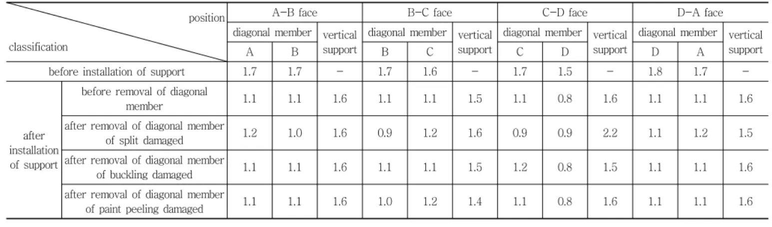
Table 11 Load reponses on diagonal members and vertical supports (except wind load) (unit : tonf)
position classification
A-B face B-C face C-D face D-A face
diagonal member vertical support
diagonal member vertical support
diagonal member vertical support
diagonal member vertical support
A B B C C D D A
before installation of support 1.7 1.7 - 1.7 1.6 - 1.7 1.5 - 1.8 1.7 -
after installation of support
before removal of diagonal
member 1.1 1.1 1.6 1.1 1.1 1.5 1.1 0.8 1.6 1.1 1.1 1.6
after removal of diagonal member
of split damaged 1.2 1.0 1.6 0.9 1.2 1.6 0.9 0.9 2.2 1.1 1.2 1.5
after removal of diagonal member
of buckling damaged 1.1 1.1 1.6 1.1 1.1 1.5 1.2 0.8 1.5 1.1 1.1 1.6
after removal of diagonal member
of paint peeling damaged 1.1 1.1 1.6 1.0 1.2 1.4 1.1 0.8 1.6 1.1 1.1 1.6
Table 12 Load reponses on diagonal members and vertical supports (with wind load) (unit : tonf)
position classification
A-B face B-C face C-D face D-A face direc. of
wind load diagonal member vert.
support
diagonal member vert.
support
diagonal member vert.
support
diagonal member vert.
support
A B B C C D D A
after installation of support
after removal of diagonal member
of split damaged 1.0 1.3 0.3 6.2 8.2 2.5 3.1 1.0 5.2 8.0 5.5 1.9 X
after removal of diagonal member
of buckling damaged 1.5 0.8 0.3 5.6 7.8 2.3 2.4 2.8 4.7 8.3 6.1 2.0 X
after removal of diagonal member
of paint peeling damaged 6.3 7.3 1.3 2.2 3.4 4.2 8.1 4.7 2.7 0.5 2.2 0.6 Y
용시 풍하중 입력방향과 반대되는 jack-up력은 생략하였다.
이는 풍하중 반대 방향 측에 대해 불필요한 힘을 작용시키기 때문이다. 본 분석은 손상사재 제거후의 하중 전이 현상에 대한 검토용으로 활용하였다. Support 설치 전과 설치 후의 손상된 사재들을 종류별로 제거하면서 A, B, C, D 각을 중 심으로 사재 및 수직 support 상부에 도출되는 힘의 크기를 수치 해석적으로 평가한 결과는 풍하중을 고려하지 않았을 때와 풍하중을 고려했을 때를 구분하여 Table 11과 Table 12에 각각 도출하였다.
4.4 현장에서의 support 유압잭력 시험과 측정
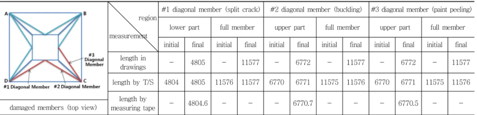
손상된 부재를 제거하기 전에 support에 의한 잭업 시험 작업시 1등급 레벨, 토탈 스테이션 및 정밀 줄자 등을 이용 하여 손상 부재 길이 변화를 평가하였다. 유압잭 력은 모든 경사 support는 30tonf, 수직 support는 10tonf 잭업시를 기 준으로 하였다. 이는 초기 해석시 관심 대상의 사재 길이가 2mm 늘어날 수 있도록 평가한 것이다. 단 송전철탑은 풍력 에 의해 상시로 영향을 받고 있고, 이에 따라 유압잭 력에 따른 변위 변화 실 계측 결과가 다르게 되어 현장에서는 경 사 support는 9tonf을, 수직 support는 6 tonf 유압잭 력을 조
절하여 손상된 부재 길이 보다 약 1mm 정도를 추가 확보하 도록 유도하였다. 이 결과는 보강 작업시에 대한 해석 신뢰 성을 입증하였고, 이를 토대로 교체될 새 부재를 제작⋅교체 하므로써 본 구조물 보강 작업을 완성하였다. 유압잭력에 따 른 사재들에서의 변위 측정 결과는 Table 13과 같다.
사재는 주주재에 용접된 연결용 브래킷에 연결되고, 경사 support 끝단은 브래킷 하단에 지그 (zig)를 이용하여 체결되 었다. 유압잭에 의해 경사 support에 부과된 9tonf의 수직 방 향 성분력은 7.74tonf이다. 이러한 잭업력에 대한 브래킷 용 접력의 안전도 평가에 있어서 설계 순간 최대 풍속 50m/sec 적용시 브래킷으로 인입되는 수직력 성분이 12.7tonf이고, 브래킷 용접부가 이를 지지하므로 잭업력에 대해서는 안전 성이 확보되었다.
4.5 신사재의 보강
기존 사재 축강성 보강 방안중의 하나는 적절한 보강 재료 를 사재 내에 밀실하게 충전시키는 것이다. 그러나 충전 상 태가 불량해질 경우 축강성 보강 효과가 없을 뿐만 아니라, 향후 재보강을 할 수 없도록 하는 역효과까지 창출하게 된 다. 따라서 교체될 신사재에 대한 충전 보강은 공장 제작하
Table 13 Displacements of the diagonal members due to jacking force (unit : mm)
region measurement
#1 diagonal member (split crack) #2 diagonal member (buckling) #3 diagonal member (paint peeling) lower part full member upper part full member upper part full member initial final initial final initial final initial final initial final initial final length in
drawings - 4805 - 11577 - 6772 - 11577 - 6772 - 11577
length by T/S 4804 4805 11576 11577 6770 6771 11575 11576 6770 6771 11575 11576 length by
measuring tape - 4804.6 - - - 6770.7 - - - 6770.5 - -
damaged members (top view)
note : each of diagonal members of #1, #2, #3 was assembled by two parts, upper one and lower one
Table 14 Components size of grouting material filled up diagonal members
cement sand water admix
40kg 40kg 16L 0.4kg
Table 15 Mixing ratio concrete filled up diagonal members
w/c s/a unit weight (kg/m
3)
% w c s g pc ad 1 ad 2
40.4 53 202 500 826 755 8.0 0.025 0.25
notes : 1) Gmax : 13mm, pc : superplasticizer (pc) ad 1 : air entraining agent ad 2 : thickener
2) slump : 6.2cm, air content : 5%, compressive strength : 40MPa
member filled with filler curve of loading test Fig. 6 Test of frictional resistance for filler in diagonal member
여 보강재가 충분히 충전되도록 함으로써 추후 발생할 수 있 는 D각 기초의 추가 침하에 저항할 수 있도록 하였다. 본 현 장에서 제거된 구사재를 분해해 본 결과 상기와 같은 미충전 상태가 확인되었다. 여기서 신사재에 대한 충전재로 팽창성 그라우팅재 및 콘크리트를 선택하였고, 이에 대한 기초 실험 을 수행하여 사재의 복합 거동 수준을 확인하였다. Table 14 는 사재 내부의 보강재로 충전한 그라우팅 재의 성분표를, Table 15는 콘크리트 충전재의 배합 설계 내용을 도시하였다.
4.6 보강 신사재의 실험검증
시멘트 몰탈 (팽창성 그라우팅재) 및 콘크리트를 충전하여 보강한 교체용 사재에 있어서 사재와 충전재와의 합성 거동 상태를 실험적으로 확인하였다. 아를 위해 1.5m 길이의 일반 강관에 충전재를 타설하고, 타설 후 25일 양생 기간을 거친 후, 충전재의 탈락 확인을 실험한 결과, 시멘트 몰탈의 경우 는 3.7 tonf에서, 콘크리트는 40.9tonf에서 충전재와 모재
(강관사재)가 분리되었다. 따라서 콘크리트 충전 방식에 따 른 사재의 합성 거동 능력이 우수한 것으로 평가되었다. 이 결과를 현장화하면 4.805m 사재는 3.2배로, 6.772m 사재는 4.5배의 크기로 충전재에 의한 마찰 저향력이 확대된다. Fig 6에는 부재 내의 충전제 탈락 시험 모식도와 시험 결과가 제 시되었다.
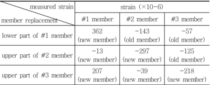
4.7 교체사재 변형률 계측결과
보강용 교체 사재에 변형률 게이지를 부착하고, 교체 완료 시 발생하는 변형률 값을 계측하여 보강된 사재가 받는 부재 력을 평가하였다. #1~#3의 사재를 교체한 후, 자연 환경 하 에서 교체 사재에서의 변형률 변화를 보면, #1 교체 사재의 경우 변형률이 207×10-6인 인장력을 받으며, #2 교체 사재와
#3 교체 사재는 변형률이 각각 -39×10-6 및 -218×10-6인 압 축력을 받고 있다. 이를 바탕으로 교체 사재에 있어서 충전 콘크리트와의 합성 여부 관계가 인장시는 비합성 구조로, 압 축시는 합성 구조로 평가되었다. 부재력은 인장에서 5.7tonf, 압축에서 14.7tonf이다. 따라서 각 부재는 설계 내력을 충분 히 갖고 있음이 입증되었다. 그 결과는 Table 16과 같다.
Table 16 Strain changes in diagonal members at each step of member replacement
measured strain member replacement
strain (×10-6)
#1 member #2 member #3 member lower part of #1 member 362
(new member)
-143 (old member)
-57 (old member) upper part of #2 member -13
(new member)
-297 (new member)
-125 (old member) upper part of #3 member 207
(new member)
-39 (new member)
-218 (new member) note : (-) compression, (+) tension
5. 결 론
(1) 손상된 구조물 성능 개선시 구조물을 최대한 축성 초 기 상태로 전환시키고자 하는 일환으로, 기초 침하에 따른 송전 철탑 손상 부재의 탄성 회복에 근간을 두고 구부재를 신부재로 교체하였다. 본 연구에서는 신부재 교체시의 새로운 실증적 기법을 창안⋅적용하므로써 송전 철탑 성능 개선과 관련된 효율적 유지 관리 방안 을 개발하였다.
(2) 적용된 support 유압잭 시스템 구조와 규모는 송전 철 탑 풍해석을 통해 교체될 손상 부재 위치에서 소량의 역 변위 변화량에 대한 경우 수 분석에 따라 유압력과 시스템 형상을 새롭게 창안한 결과이고, 그 결과가 매 우 긍정적인 것으로 분석되므로 송전 철탑 사재 보강 방안의 정당성을 확인하였다.
(3) 사재 교체시 작업중 정밀 계측기에 따른 계측 결과는 사전 수치 해석에 따라 예상했던 결과와 매우 유사하 고, 또한 사재 강관 내의 콘크리트 충전재 탈부착 시험 에 따라 도출된 결과는 그 성능의 우수성이 확인되었 으므로 송전 철탑 거동 예측의 정확성과 충전재 충전 방식에 따른 보조적 축력 보강 방식의 실효성을 입증 하였다.
(4) 본 연구는 대상체에 대한 매우 제한적 여건과 조건하 에 수행된 결과이다. 따라서 다수의 실험적 결과를 바 탕으로 보다 신뢰성 있는 연구가 수행되어야 함을 명 기한다.
감사의 글
본 연구는 금오공과대학교 교수연구년제에 의하여 연구된 실적물이며, 이에 감사드립니다. 또한 본 연구를 위해 많은 지원을 아끼지 않으신 관계제위께도 감사를 드립니다.
참고문헌
1. Han, Sang Mook, Pang, Gi Sung, Kim Do Gyeum, Jung, Song Soo, “Study on Maintenance Management on Concrete Mat Foundation of the Tansmission Tower Construction of 345kV Yong Heung T/L”, Journal of Regular Conference, Korea Society of Civil Engineers (KSCE), 2004, pp.509-512.
2. KEPCO, “Research on the Life Management Control for the Young-heung T/L 345kV Electric Power Transmission Tower on the Sea in Korea”, 2004.
3. KEPCO, “Design Standards for the Processing Electric Power Transmission Tower in Korea”.
4. KEPCO, “Management Guidelines for the Foundation of Young-heung Electric Power Transmission Tower on the Sea in Korea”.
5. KEPRI, “Study on Life Cycle Management for the 345kV Electric Power Transmission Tower on Young-heung T/L in Korea”, 04Kepri-463, 2004.8.
6. KISTEC, MLTM, “Detailed Guidance of Safety Inspection and In-depth Safety Inspection in Korea”, 2003.12 & 2009.3.
7. KOPEC, “Design Drawings for the I, II Types of SB2 345kV Electric Power Transmission Tower at Sihwa Lake on Young-heung T/L Construction in Korea”, 2002.8.
8. KOPEC, “Design Drawings for the I, II Types of SB2 345kV Electric Power Transmission Tower on Open Sea on Young-heung T/L Construction in Korea”, 2002.8.
9. KOPEC, “Design Drawings for the I, II Types of SD2 345kV Electric Power Transmission Tower at Sihwa Lake on Young-heung T/L Construction in Korea”, 2002.8.
10. Lee, Ho Beom, Jang, Il Young, “Aging Deterioration for Electric Power Transmission Tower on Offshore Through Periodic Inspections”, Journal of the Korea Institute for Structural Maintenance and Inspection, vol. 16, No. 4. 2012.07, Serial No.74.
11. ThreeTECH Co., Ltd., “Report on Structural Safety Evaluation and Countermeasure for the No. 108 Electric Power Transmission Tower at islet on Young-heung T/L in Korea”, 2006.10.
Received : 06/15/2012
Revised : 10/22/2012
Accepted : 12/12/2012
요 지
일반적으로 송전철탑 부재들의 보강은 적절한 그라우팅재를 활용한 인젝션과 구조 보강재 부착을 이용한 단면 확장에 따른 강성보강 방 식을 주로 사용한다. 이와 같은 그라우팅 인젝션 및 단면보완은 주로 축력능력을 확장시키는 데에 의미를 갖는다. 그렇지만 보다 안정적 상태를 유지케 할 수 있는 보강방안이 적극 요구되는데 그 방법은 좌굴에 의해 손상을 받은 부재를 원상태의 길이로 환원시키고, 또한 내부 적 보강효과를 동시에 갖는 새로운 부재로 교체하는 것이다. 본 연구에서는 기초침하로 구조적 손상을 받은 송전철탑의 손상회복을 위한 실증적 과정으로 우선 현장에서의 손상도 확인점검과 손상상태 및 회복상태에 대한 수치 해석적 결과를 도출하였고, 새롭게 고안한 잭킹 시스템을 이용하여 보강된 부재를 교체하는 과업을 수행하였다. 이 결과는 송전철탑 유지관리의 차원상승 효과를 갖게 한다.