초전도 전류제한소자를 적용한 DC 차단기의 동작 특성 분석
정병익*
Analysis of Operation Characteristics of DC Circuit Breaker with Superconducting Current Limiting Element
Byung-Ik Jung
*요 약
DC에는 전류 영점이 없기 때문에 DC 차단기의 차단 동작시 아크가 발생한다. 이때 발생하는 아크의 크기 에 따라 회로 차단기의 열화 또는 그리드에 치명적인 사고를 발생시킬 수 있다. 따라서 HVDC의 상용화에 있 어서 DC차단기의 차단 성능의 안정성 확보는 대단히 중요한 부분이다. 본 연구에서는 DC 차단기의 성능과 신뢰성을 향상시키기 위해 초전도체가 적용된 LC 차단기를 제안하였다. 초전도 LC 차단기는 기존 LC 차단기 의 인덕터에 초전도 코일을 적용한 구조로 되어있다. 초기 고장 전류를 제한하는 것 외에도 고장 발생시 안정 적인 전류 0점을 생성한다. 이를 확인하기 위해 EMTDC / PSCAD 프로그램을 통해 시뮬레이션을 수행하였 다. 또한 초전도 LC 차단기는 일반 코일이 적용된 LC 차단기와의 동작 특성을 비교하였다. 그 결과 초전도 코일이있는 LC 회로 차단기는 일반 코일이있는 LC 회로 차단기에 비해 초기 고장 전류를 약 12kA 더 제한하 는 것으로 나타났다. 이러한 결과를 통해서 DC 차단기의 아크 소화 시간을 약 0.16 초 단축시킬 수 있었고, 이를 통해 회로 차단기의 전기적 부담이 줄어드는 것을 확인할 수 있었다.
ABSTRACT
Since DC has no zero point, an arc occurs when the DC circuit breaker performs a shutdown operation. In this case, a fatal accident may occur in the circuit breaker or in the grid, depending on the magnitude of the arc. Therefore, the shutdown performance and the reliability of the circuit breaker are important in the commercialization of HVDC. In this study, a superconducting LC circuit breaker was proposed to improve the performance and the reliability of the DC circuit breaker. The superconducting LC circuit breaker applied a superconducting coil to the inductor of the existing LC circuit breaker. Other than limiting the initial fault current, it also creates a stable zero point in the event of a fault current. To verify this, simulation was performed through EMTDC/PSCAD. Furthermore, the superconducting LC circuit breaker was compared with the LC circuit breaker with a normal coil. As a result, it was found that the LC circuit breaker with the superconducting coil limited the initial fault current further by approximately 12 kA compared to the LC circuit breaker with a normal coil. This reduced the arc extinguish time by approximately 0.16 sec, thereby decreasing the elctrical power burden on the circuit breaker.
키워드
Direct current, Superconductor, DC circuit breaker, LC resonance 직류 전류, 초전도체, 직류 차단기, LC 공진
* 교신저자 : 동강대학교 전기과 ㆍ접 수 일 : 2020. 10. 23 ㆍ수정완료일 : 2020. 11. 19 ㆍ게재확정일 : 2020. 12. 15
ㆍReceived : Oct. 23, 2020, Revised : Nov. 19, 2020, Accepted : Dec. 15, 2020 ㆍCorresponding Author : Byung-Ik Jung
Dept. Electrical engineering, Dongkang University, Email : [email protected]
http://dx.doi.org/10.13067/JKIECS.2020.15.6.1069
Ⅰ. Introduction
Recently, the DC power grid has been increasing due to the advances in renewable energy and distributed power. The DC power grid experiences no loss caused by the skin effect and the reactance component. Thus, power transmission efficiency is high, and low-loss, long-distance power transmission is possible. For this reason, research on the HVDC system has been actively conducted worldwide. The shut-down technology and the performance of the DC circuit breaker are important in improving the stability and the reliability of the HVDC system. Since DC has no zero point, an arc occurs during the operation of the circuit breaker.
The arc may cause a fatal accident in the circuit breaker, or in the grid. Therefore, a zero point must be artificially created to prevent an arc.
The divergent current oscillation method connects the LC circuit and the mechanical circuit breaker in parallel (LC circuit breaker). In the event of a fault current, it creates an artificial current zero point by generating the oscillating current in the LC circuit. This method is the most stable and reliable among the shutdown methods of the mechanical circuit breaker. However, it has limitations when used under high voltage and ultra-high voltage conditions[2-7].
In this study, a superconductor was applied to the LC circuit of the divergent current oscillation method. The inductor of the LC circuit was constructed by using a wire-type superconductor.
In the event of a fault current, the superconducting coil is quenched, and generates resistance to limit the fault current. Moreover, the LC circuit creates a zero point by generating divergent current. This enables the mechanical contact to perform a stable operation. To verify this, the characteristics of the normal circuit breaker were compared with those of the superconducting LC circuit breaker by using the EMTDC/PSCAD simulation software.
Ⅱ. Preparing a manuscript
2.1 Mechanical circuit breaker
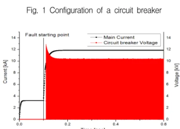
Fig.1 shows the mechanical circuit breaker that was implemented by using EMTDC/PSCAD. For the arc occurring at the contact when the circuit breaker is opened, the Mayr model of the EMTDC/PSCAD simulation was used. The Mayr model is the most similar to the shut-down characteristics of the actual circuit breaker[1], [3], [9-10].
Fig. 2 is a graph showing the arc voltage occurring at both ends of the circuit breaker when it is opened. An arc with a magnitude of approximately 13 kV was generated and the fault current was not blocked. So that the mechanical circuit breaker can perform a stable shut-down operation, the shutdown operation must be performed before the magnitude of the fault current reaches its peak[2]. An artificial zero point must be created within 0.5 ms because the magnitude of the fault current reached its peak at 0.5 ms after fault started.
Fig. 1 Configuration of a circuit breaker
Fig. 2 Configuration of a circuit breaker
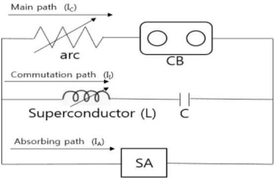
Fig. 3 Configuration of a circuit breaker 2.2 Circuit breaker applied the LC element Fig. 3 shows the designed circuit breaker circuit of the divergent current oscillation method by using EMTDC/PSCAD. The LC circuit breaker consisted of a main path, a commutation path, and an absorber path. First, the main path was the contact of the circuit breaker. The commutation path was composed of an inductor and a capacitor. The inductor and the capacitor were connected in series, and they caused the current to diverge by using the resonance frequency in the event of a fault current. In this instance, the resonance frequency equation is as shown in equation (1)[3].
(1)
To perform the shutdown operation within the peak arc voltage, divergent current must reach a zero point within 16 ms.
sin
(2)
The divergent current generated by L and C in the event of a fault can be calculated by using equation (2)[4]. Through equation (2), the inductance (L) and capacitance (C) values that could create a zero point within 16 ms were
derived. The components of the LC circuit breaker used in a simulation are shown in Table 1. In this study, a normal coil and a superconducting coil were applied to the inductor of the commutation path, respectively. The normal coil and the superconducting coil had the same inductance value.
exp
(3)
The quench characteristics of the superconducting coil were constructed, as shown in equation (3) [3]. The characteristics of the superconductor represent the characteristics of the superconducting wire from AMSC. From equation (3), the Rm of the superconductor is 5Ω. This is the resistance value of the superconductor when the length of the coil constituting the L value is 10 m. The superconductor reaches the peak quench resistance within 2 ms. Therefore, 0.75 ms was applied to the time constant TSC. Finally, the absorber path was constructed by using a gapless type surge arrest(SA). The absorber path discharges residual current to the earth after the circuit breaker performs a shutdown operation.
2.3 Configuration of simulation
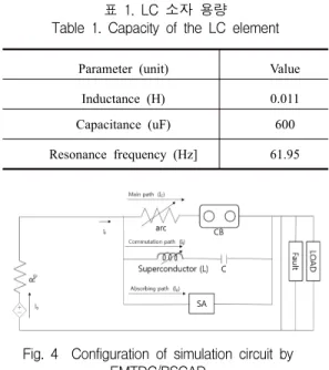
Fig. 4 shows the constructed DC simulation grid
by using EMTDC/PSCAD. The applied voltage was
100 kV, and the line resistance was 1Ω. In this
case, the normal current was 3 kA. Still, the rated
voltage and the current for DC grids have not
normalized worldwide. Therefore, the magnitude of
the fault current cannot be expected. The
magnitude of the fault current was set to 30 kA.
Parameter (unit) Value
Inductance (H) 0.011
Capacitance (uF) 600
Resonance frequency (Hz] 61.95
표 1. LC 소자 용량
Table 1. Capacity of the LC element
Fig. 4 Configuration of simulation circuit by EMTDC/PSCAD
Ⅲ. Experimental results
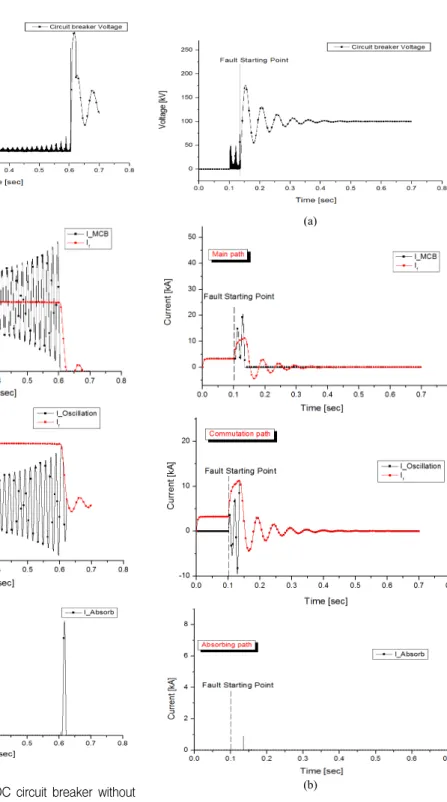
Fig. 5 shows the characteristics graph when a normal coil was applied to the LC circuit breaker.
A fault occurred at 0.1 sec. Fig. 5(a) shows the voltage graph of the circuit breaker. After a fault occurrence, the circuit breaker contact was opened in the main path. However, an unstable state was observed as the operation of the circuit breaker was delayed by the arc. The arc extinguishing time is about 0.5 sec. After a zero point was created by the LC path, and the circuit breaker was fully opened. Fig. 5(b) shows the current graph of the LC circuit breaker. When the fault current occurred, divergent current was generated by LC, and a zero point was created. When the circuit breaker was fully opened by the zero point, the residual current was discharged by the absorber path. At this time, the magnitude of the fault current is about 30 kA.
It takes about 0.5 sec for the fault current to reach zero point and completely shut off.
Fig. 6 shows the characteristics graph when a superconducting coil was applied to the LC circuit
breaker. A fault occurred at 0.1 sec as in the case where a normal coil was applied. The magnitude of the fault current was approximately 12 kA, which was approximately 2.5 times lower compared to the normal coil. This is because that the fault current was limited due to the quench characteristics of the superconductor. Fig. 6(a) shows the voltage graph of the circuit breaker. The arc extinguishing time is about 0.14 sec. The arc extinguishing time in the circuit breaker also decreased because the fault current was limited by the superconductor. Fig. 6(b) shows the current graph of the LC circuit breaker.
As with Fig. 5(b), the current diverged due to the LC path immediately after the fault occurrence and a zero point was created. This allowed the circuit breaker to perform safe operation, and then the residual current was discharged by the absorber path. The stable operation of the superconducting coil was confirmed when the superconducting coil was applied to the LC circuit breaker. When a fault current occurred, the superconducting coil was quenched, and the fault current was limited by approximately 19 kA. In addition, the arc extinguishing time was reduced by about 0.36 sec. Furthermore, it was confirmed that divergent current is generated by the LC path due to the superconducting coil
Ⅳ. Conclusion
Recently, interest in the DC power grid has increased due to the advances in renewable energy and distributed power. The shutdown technology and performance of the circuit breaker are very important in securing the stability and reliability of the DC power grid.
In this study, a superconductor was applied to
improve the performance of the LC circuit breaker
that can be applied to the DC power grid. As
superconductors have zero resistance characteristics
below the critical temperature, they normally cause
(a)
(b)
Fig. 5 Simulation results of DC circuit breaker without superconductor
(a) Circuit breaker voltage (b) Currents of LC circuit breaker
(a)
(b)
Fig. 6 Simulation results of DC circuit breaker with a superconductor (a) Circuit breaker voltage (b) Currents
of LC circuit breaker
no current loss. However, they have high resistance values in the event of a fault due to their quench characteristics, and can limit the fault current. In this study, a superconducting coil was applied to the inductor of the LC circuit breaker, and simulation was performed by using the EMTDC/PSCAD software. Moreover, the LC circuit breaker with the superconductor coil was compared with the LC circuit breaker with a normal coil to verify performance improvement. As a result, it was found that the LC circuit breaker with the superconducting coil limited the fault current further by approximately 19 kA, compared to the LC circuit breaker with a normal coil in the fault in the DC grid. So, this decreased the arc extinguishing time by approximately 0.16 sec, which also decreased the mechanical burden on the circuit breaker.
Furthermore, it was confirmed that the superconductor coil creates divergent current as well as a zero point in the LC path in a stable manner.
The existing mechanical circuit breaker was difficult to use under high voltage and ultra-high voltage conditions because of its limited shutdown capabilities under high voltage and current, as well as the degradation of the circuit breaker contact. However, if further research is conducted on the proposed LC circuit breaker with a superconductor, it will be possible to apply the mechanical circuit breaker under high voltage and ultra-high voltage conditions.
References
[1] S. Jiang, “Report-PSCAD component Breaker Arc,”
Manitoba HVDC Research Centre, 2013.
[2] S. lyer, W. G. Dunford, and M. Ordonez, “DC distribution systems for homes,” in Proc. IEEE Power Energy Soc. General Meet., Denver, USA, 2015, pp. 1-5.
[3] H. W. Choi, I. S. Jeong, S. Y. Park, and H. S. Choi.
“Characteristics of superconducting Coil-type DC Fault
Current Limiter to Increase Stability in the Grid Connection PV Generation System,” IEEE Trans. Appl.
Supercond., vol. 28, no. 3, 2018, pp. 5600904.
[4] S. Tokuyama, H. Sugawara, “DC.Circuit breaker”, United States Patent no. US4216513A, 2013.
[5] Z. Ganhao, “Study on DC circuit breaker,” in Proc.
5th Int. Conf. Intell. Syst. Des. Eng. Appl., Hunan, China, 2014, pp. 942–945.
[6] W. R. L. Garcia, P. Tixador, B. Raison, A. Bertinato, B. Luscan, and C. Creusot, “Technical and economic analysis of the R-Type SFCL for HVDC grids protection,” IEEE Trans. Appl. Supercond., vol.
27, no. 7, Oct. 2017, Art. no. 5602009.
[7] F. Zheng, C. Deng, L. Chen, S. Li, Y. Liu, and Y.
Liao, “Transient performance improvement of microgrid by a resistive superconducting fault current limiter,” IEEE Trans. Appl. Supercond., vol.
25, no. 3, June 2015, Art. no. 5602305.
[8] A. Mokhberdoran, A. Carvalho, H. Leite, and N.
Silva “A review on HVDC circuit breakers,” in Proc.
Renewable Power Generation Conf., Naples, Italy, 2014, pp. 1-6.
[9] B. X. Zhiyuan, L. Y. Geng, S. Yanabu, “DC circuit breaker using superconductor for current limiting,” IEEE Trans. Appl Supercond., vol25, no.2, Oct. 2014, pp. 5600207
[10] K. Zhang and H.-J. Suh, "An analysis of multiuser diversity technology in the MIMO-OFDM system," J. of the Korea Institute of Electronic Communication Sciences, vol. 14, no. 6, Dec. 2019, pp. 1121-1128.
저자 소개
정병익(Byung-Ik Jung)