j.inst.Korean.electr.electron.eng.Vol.19,No.1,018∼026,March 2015 http://dx.doi.org/10.7471/ikeee.2015.19.1.018 18
Isolation Enhancement of Internal MIMO Antenna
Pil Hyun Jung
*, Woon Geun Yang
*★Abstract
In this paper, we proposed and evaluated the performance of an internal MIMO (Multiple Input Multiple Output) antenna for multiband operations including LTE (Long Term Evolution) 700/2300/2500. And to enhance the isolation characteristic, a parasitic element is designed and applied. The proposed single antenna has a volume of 60 mm(W) x 38 mm(L), and the ground plane is 60 mm(W) x 100 mm(L). The parasitic element used for enhancing the isolation of the antenna was designed with a copper on FR4 sized 60 mm(W) x 20 mm(L) x 1.6 mm(H), and the pattern size is 60 mm(W) x 15 mm(L). Simulated and measured results showed that LTE 700/2300/2500, DCS (Digital Cellular Service: 1710-1880MHz), K-PCS (Korea-Personal Communication Service:
1750-1870MHz), US-PCS (US-Personal Communication Service: 1850-1990MHz), WCDMA (Wideband Code Division Multiple Access: 1920-2170MHz), Wibro (2300-2390MHz), Bluetooth (2400-2483MHz), WLAN (Wireless Local Area Network: 2400-2483.5MHz), US-WiMAX (US-World interoperability for Microwave Access:
2400-2590MHz) frequency bands were covered with S11 values less than -6dB (VSWR < 3). Simulated and measured results on S21 at 730MHz for the firstly designed MIMO antenna showed -5.50dB and -5.65dB, respectively. When with the parasitic element at the separated ground plane to enhance the isolation performance, -10.33dB and–12.90dB are obtained for the simulation and measurement, so the enhanced isolation performance at lower frequency band (617-867MHz) is confirmed.
Key words: MIMO, Isolation, Parasitic element, Multiband, Internal antenna
* Dept. of Electronics Engineering, Incheon National University
★ Corresponding author
[email protected], 032-835-4767
※Acknowledgement
-This work was supported by Incheon National University Research Grant in 2013.
Manuscript received Jan. 14, 2015; revised Feb. 10, 2015;
accepted Feb. 13. 2015.
This is an Open-Access article distributed under the terms of the Creative Commons Attribution Non-Commercial License(http://creativecommons.org/licenses/by-nc/3.0) which permits unrestricted non-commercial use, distribution, and reproduction in any medium, provided the original work is properly cited.
ISSN: 1226-7244 (Print) ISSN: 2288-243X (Online) 논문번호 15-01-03
I. Introduction
In recent years, the necessity and availability of portable terminals for wireless communication have increased rapidly. As a result, the high-speed data transmission of next generation mobile communication system is more highly valued. In order to realize high-speed data transmission,
technologies that efficiently use the restricted frequencies in limited space are necessary. One of these technologies is MIMO (multiple input multiple output), which involves the use of multiple antennas. The proposed MIMO system by the Bell Research Institute has enabled high-speed data transmission using several antennas at the transmitter and receiver to increase the channel capacity[1,2]. However, it is very challenging to have the high isolation characteristics, because the adjacent multiple antennas cause strong electromagnetic mutual coupling and interferences.
So far, for isolation improvement between antenna elements inside mobile handsets, many researchers have been trying to find new techniques[3-14], such as adjusting optimal antenna positions[3], how to apply diversity techniques[4,5], how to use decoupling networks[6,7], how to insert SRR (Splite Ring Resonator), AMC (Artificial Magnetic Conductor), EBG (Electromagnetic Band Gab), EBG without common ground plane[8-10], how to use
slot or slit on the ground plane[11,12], how to use parasitic elements[13,14], and so on.
The LTE (Long Term Evolution) operation is in demand for modern mobile devices such as smart phones, laptop computers, and tablet computers. The LTE operation can provide a much higher communication data rate than the WWAN (Wireless Wide Area Network) operation. It mainly includes three operation bands of the LTE 700 (704-787MHz), LTE 2300 (2300-2400MHz), and LTE 2500 (2500-2690MHz)[15-17].
These antennas which can cover all the operating bands of LTE operations are attractive for use in mobile devices as the main internal antenna for voice and data communications. However, it is noted that the LTE is best suited for the MIMO operation[16-18].
In this paper, we propose an internal MIMO antenna for multiband operations including LTE 700/2300/2500 frequency bands with S11 values less than -6dB (VSWR < 3). We are able to achieve the multiband operation by combining a multiband G-shape monopole antenna[19] with wideband top loop loaded monopole antenna[20] in Section II.
Next, we propose the MIMO antenna with a parasitic element[13] and a separated ground plane[10] that could be used for multiple services.
The previous researches[3-14] usually deal with the isolation enhancement for a single band, but we conduct the isolation enhancement of a multiband, including LTE 700/2300/2500, antenna. We try to enhance an isolation characteristic by using one parasitic element with the separated ground plane in Section III, and conclusion follows in Section IV.
A HFSS (High Frequency Structure Simulator) of the Ansoft Corporation based on the FEM (Finite Element Method) is employed to analyze the proposed antenna in the design process and to compare the simulation and experimental results.
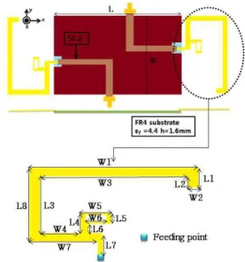
II. Proposed MIMO Antenna Fig. 1 shows the geometry of the proposed internal MIMO antenna. Also, the parameters of the proposed antenna are presented in Table 1. The single antenna size is 60 mm(W) × 38 mm(L).
Ground plane size is 60 mm(W) × 100 mm(L).
Ground plane is an inexpensive FR4 substrate with a dielectric constant of 4.4 and a thickness of 1.60 mm. The dimension of the feeding point is 2.00 mm(W) x 2.00 mm(L).
Fig. 1. Geometry of the proposed MIMO antenna Table 1. Design parameters of the proposed MIMO antenna
(unit : mm) Parameter Length Parameter Length
L 100 W 60
L1 9 W1 60
L2 5 W2 4
L3 25 W3 52
L4 9 W4 14
L5 5 W5 11
L6 4 W6 7
L7 11 W7 24
L8 33 W8
Table 1 shows values of the design parameters which were obtained through the simulation.
Fig. 2 depicts a design process of the proposed MIMO antenna and Fig. 3 shows the simulated S11 for Fig. 2. The proposed antenna has a G-shape branch with a small loop. Generally, two branches of the different length have multiband operation characteristics[19]. Also, a loop antenna can obtain an wideband impedance bandwidth[20]. We can convert 1708-2750MHz to 1790 -2750MHz by adding
20 j.inst.Korean.electr.electron.eng.Vol.19,No.1,018∼026,March 2015
one small loop to the G-shape antenna. As a result, DCS (Digital Cellular Service: 1710-1880MHz), K-PCS (Korea-Personal Communication Service:
1750-1870MHz) bands are supported additionally.
(a) (b)
Fig. 2. Design process of the proposed antenna. (a) G-shape branch, (b) G-shape branch with a loop
Fig. 3. Simulated S11for Fig. 2
Fig. 4 shows the implemented MIMO antenna.
The implemented antenna is fed with a coaxial cable of 50Ω. Fig. 5 shows measurement and simulation results on the S11and S22 of the proposed antenna. The results show a good agreement between measurement and simulation.
Fig. 4. Photograph of the implemented MIMO antenna
Fig. 5. Simulated and measured S11and S22
The implemented MIMO antenna satisfied multiple operating bands including LTE 700/2300/2500, DCS, K-PCS, US-PCS (US-Personal Communication Service: 1850-1990MHz), WCDMA (Wideband Code Division Multiple Access: 1920-2170MHz), Wibro (2300-2390MHz), Bluetooth (2400-2483MHz), WLAN (Wireless Local Area Network: 2400-2483.5MHz), US-WiMAX (US-World interoperability for Microwave Access: 2400-2590MHz) frequency bands with S11 values less than -6dB (VSWR < 3).
Fig. 6. Simulated and measured S21
Fig. 6 shows simulated and measured S21 for the proposed MIMO antenna. From Fig. 6, we found that the S21 characteristics are -5.50dB through the simulated result and -5.65dB through the measured result. We deal with enhancing the isolation characteristic by using one parasitic element in Section Ⅲ.
(a) At 748MHz (LTE 700)
(b) At 1795MHz (DCS)
(c) At 1810MHz (K-PCS)
(d) At 1920MHz (US-PCS)
(e) At 2045MHz (WCDMA)
(f) At 2345MHz (Wibro)
(g) At 2350MHz (LET 2300)
(h) At 2442MHz (Bluetooth and WLAN)
(i) At 2495MHz (US-WiMAX)
(j) At 2595MHz (LTE 2500)
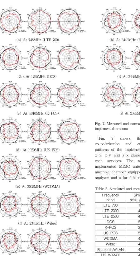
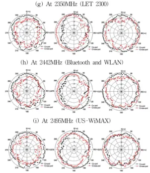
Fig. 7. Measured and normalized radiation patterns of the implemented antenna
Fig. 7 shows the normalized measured co-polarization and cross-polarization radiation patterns of the implemented MIMO antenna in the x-y, z-y and z-x planes at center frequencies of each services. The radiation patterns of the implemented MIMO antenna were measured in an anechoic chamber equipped with HP 8510C network analyzer and a far field measurement system.
Table 2. Simulated and measured antenna peak gain Frequency
band Simulated
peak gain(dBi) Measured peak gain(dBi)
LTE 700 1.38 2.04
LTE 2300 4.35 4.16
LTE 2500 4.23 4.37
DCS 5.21 3.98
K-PCS 2.67 2.97
US-PCS 5.35 4.26
WCDMA 4.69 4.01
Wibro 4.38 3.65
Bluetooth/WLAN 4.55 3.89
US-WiMAX 4.29 3.92
22 j.inst.Korean.electr.electron.eng.Vol.19,No.1,018∼026,March 2015
From this Table 2, we can see that the simulated peak gain and measured peak gain of LTE 700 are 1.38dBi, 2.04dBi, respectively. For the LTE 2300 band, the simulated peak gain and measured gain are 4.35dBi, 4.16dBi, respectively. For the LTE 2500 band, the simulated peak gain and measured gain are 4.23dBi, 4.37dBi, respectively. For the DCS band, the simulated peak gain and measured gain are 5.21dBi, 3.98dBi, respectively. For the K-PCS band, the simulated peak gain and measured gain are 2.67dBi, 2.97dBi, respectively. For the US-PCS band, the simulated peak gain and measured gain are 5.35dBi, 4.26dBi, respectively. For the WCDMA band, the simulated peak gain and measured gain are 4.69dBi, 4.01dBi, respectively. For the Wibro band, the simulated peak gain and measured gain are 4.38dBi, 3.65dBi, respectively. For the Bluetooth and WLAN band, the simulated peak gain and measured gain are 4.55dBi, 3.89dBi, respectively. For the US-WiMAX band, the simulated peak gain and measured gain are 4.29dBi, 3.92dBi, respectively.
The results shows proper characteristics for the application of this antenna.
Ⅲ. Isolation Enhancement by using Parasitic Element with a Separated
Ground Plane
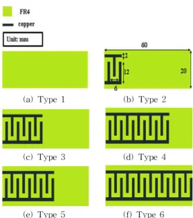
Parasitic elements can have various geometries, we choose one specific interdigital shape. Fig. 8 shows applied parasitic elements. The proposed parasitic elements are located in the center of a separated ground plane. The parasitic elements used for enhancing the isolation of the antenna was designed by using a copper on FR4 sized 60 mm(W) x 20 mm(L) x 1.6 mm(H).
Fig. 9 shows a simulated S21 characteristics according to changing types of parasitic elements.
According to each geometry of parasitic elements, the S21 characteristics at 703MHz are –9.04dB for type 1, -9.24dB for type 2, -9.45dB for type 3, -9.85dB for type 4, -10.20dB for type 5, and – 10.33dB for type 6. Through the result, we can confirm two things. Firstly, separating ground plane at the center can help the MIMO antenna to have better isolation characteristic through S21result
(a) Type 1 (b) Type 2
(c) Type 3 (d) Type 4
(e) Type 5 (f) Type 6
Fig. 8. Geometry of the proposed parasitic elements
Fig. 9. Simulated S21characteristics according to changing types of parasitic elements
for type 1. This is because separating ground plane at the center can prevent a mutual coupling current moving through the ground plane. Secondly, we can obtain better the isolation characteristic by changing the geometry of parasitic elements. Type 6 gives best performance for the limited area.
Fig. 10 shows simulated current distributions at 730MHz for with and without parasitic element type 6 in Fig. 8-(f). Each of the current distributions are a near field analysis. Fig. 10 indicates the current distributions from the red color (1000 v/m) to the blue color (0 v/m). According to this changes of the
colors on the ground plane, we can confirm the reduced mutual coupling between two antenna.
(a)
(b)
Fig. 10. Simulated current distributions at 730MHz.
(a) For the proposed MIMO antenna in Section II, (b) For the proposed MIMO antenna with the parasitic element type 6 in Fig. 8-(f)
Fig. 11. Implemented MIMO antenna with the parasitic element at the separated ground plane
Fig. 11 shows the implemented MIMO antenna with the parasitic element at the separated ground plane. The implemented antenna is fed with a coaxial cable of 50Ω.
Fig. 12. Simulated S-parameter characteristics with parasitic element type 6 in Fig. 8-(f)
Fig. 13. Measured S-parameter characteristics with parasitic element type 6 in Fig. 8-(f)
Fig. 12 and Fig. 13 show simulated and measured S-parameter characteristics with parasitic element type 6 in Fig. 8-(f). The implemented MIMO antenna with parasitic element type 6 in Fig. 8-(f) satisfied multiple operating bands including LTE 700/2300/2500, DCS, K-PCS, US-PCS, WCDMA, Wibro, Bluetooth, WLAN, US-WiMAX frequency bands with S11 values less than -6dB (VSWR < 3).
From Fig. 13, we found that the S21 characteristics at 730MHz are -10.33dB and -12.90dB for the simulated and the measured results, respectively.
Fig. 14 shows the normalized measured co-polarization and cross-polarization radiation patterns of the implemented MIMO antenna with the parasitic element type 6 at the separated ground plane in the x-y, z-y and z-x planes at center frequencies of each services. The radiation patterns of the implemented MIMO antenna were measured in an anechoic chamber equipped with HP 8510C network analyzer and a far field measurement system.
24 j.inst.Korean.electr.electron.eng.Vol.19,No.1,018∼026,March 2015
(a) At 748MHz (LTE 700)
(b) At 1795MHz (DCS)
(c) At 1810MHz (K-PCS)
(d) At 1920MHz (US-PCS)
(e) At 2045MHz (WCDMA)
(f) At 2345MHz (Wibro)
(g) At 2350MHz (LET 2300)
(h) At 2442MHz (Bluetooth and WLAN)
(i) At 2495MHz (US-WiMAX)
(j) At 2595MHz (LTE 2500)
Fig. 14. Measured and normalized radiation patterns of the implemented MIMO antenna with parasitic element type 6 in Fig. 8-(f)
Table 3. Simulated and measured antenna peak gain of the implemented MIMO antenna with parasitic element type 6 in Fig. 8-(f)
Frequency
band Simulated
peak gain(dBi) Measured peak gain(dBi)
LTE 700 0.61 1.52
LTE 2300 3.18 3.26
LTE 2500 4.39 4.62
DCS 4.05 3.97
K-PCS 0.80 1.96
US-PCS 3.70 4.25
WCDMA 3.45 4.37
Wibro 3.09 4.02
Bluetooth/WLAN 2.95 3.46
US-WiMAX 3.19 3.99
Table 3 shows the simulated peak gain and measured peak gain at center frequencies of each services. The maximum and minimum simulated peak gain are 4.39dBi at LTE 2500, 0.61dBi at LTE 700, respectively. Also, the maximum and minimum
measured peak gain are 4.62dBi at LTE 2500, 1.52dBi at LTE 700, respectively. The results confirms proper performance characteristics.
Ⅳ. Conclusion
We proposed the internal MIMO antennas for the multiband services and to enhance the isolation performance, parasitic element are applied and performances are investigated.
The MIMO antennas suitable for LTE 700/2300/2500, DCS, K-PCS, US-PCS, WCDMA, Wibro, Bluetooth, WLAN, US-WiMAX frequency bands have been proposed, implemented and evaluated. The proposed antenna has a volume of 60 mm(W) x 38 mm(L), the ground plane is 60 mm(W) x 100 mm(L).
The parasitic element used for enhancing the isolation of the antenna was designed as a copper on FR4 sized 60 mm(W) x 20 mm(L) x 1.6 mm(H), and the pattern size is 60 mm(W) x 15 mm(L).
According to simulated results on S21 of the MIMO antennas at 730MHz, we obtained –5.50dB and – 10.33dB of isolation performances for the MIMO antenna designed in Section II and the MIMO antenna with the parasitic element type 6 at the split ground in Section III, respectively. Measured results on S21 at 730MHz showed –5.65dB and -12.90dB of isolation performances for the same cases, respectively. It means that enhanced isolation performance at lower frequency band (617-867MHz) is obtained.
As a result, we confirmed that the isolation performance enhancement can be easily achieved by applying the parasitic elements to a ground plane of communication system where the MIMO antenna system can be applied.
References
[1] Dae-Geun Yang, Dang Oh Kim, and Che-Young Kim,“Design of dual-bamd mimo monopole antenna with high isolation using slotted csrr for wlan”, Microwave and Optical Technology Letters, vol. 56, no. 10, pp. 2252-2257, Oct. 2014
[2] G.J. Foschini, “Layered space-time architecture
for wireless communication in a fading environment when using multiple antennas”, Bell Labs Tech J 1, pp. 41-59, 1996
[3] D. Assanuk, M. Uthansakul, and P. Uthansakul,
“Optimal antenna positions on mobile terminal for 4×4 MIMO systems”, 6th ECTI-CON 2009, Pattaya, Chonburi, pp. 840-843, 2009
[4] H.-W. Son, “Design of dual-polarized microstrip antenna with high isolation using capacitive feeds”, IEEE Electronics Letters, vol. 45, no. 11, pp. 533-534, May 2009
[5] X. Wang, W. Chen, Z. Feng, and H. Zhang,
“Compact dual-polarized antenna combining printed monopole and half-slot antenna for MIMO applications”, IEEE AP-S Int. Symposium, Charleston, SC, pp. 1-4. Jun. 2009
[6] S.-C. Chen, Y.-S. Wang, C.-W. Ling, and S.-J.
Chung, “A new isolation dual-antennas with miniature decoupling network design”, IEEE AP-S Int.
Symposium, Honolulu, HI, pp. 3125-3128. Jun. 2007 [7] C.-Y. Lui, Y.-S. Wang, and S.-J. Chung, “Two nearby dual-band antennas with high port isolation”, IEEE AP-S Int. Symposium, San Diego, CA, pp. 1-4, Jun. 2008
[8] Itoh J., Michishita N., and Morishita H., “A study on mutual coupling reduction between two inverted-F antennas using mushroom-type EBG structures”, Antennas and Propagation Society International Symposium, San Diego, CA, pp. 1-4, Jul. 2008 [9] Bayraktar Z., Gregory M., and Werner D.H.,
“Composite planar double-sided AMC surfaces for MIMO applications”, Antennas and Propagation Society International Symposium, APSURSI '09. IEEE, Charleston, SC, pp. 1-4, Jun. 2009
[10] Won-Sang Choi and Hong-Min Lee, “Isolation enhancement between two dual-band microstrip patch antennas using EBG structure without common ground plane”, Journal of KIEES, vol. 23, no. 3, pp.
306-313, Mar. 2012
[11] Ki-Jin Kim, Won-Gyu Lim, and Jong-Won Yu,
"High isolation internal dual-band planar inverted-F antenna diversity system with band-notched slots for MIMO terminals", Proc. of the 36th European Microwave Conference, pp. 1414-1417, 2006
[12] Shin Y.S. and Park S.O., “Diversity planar monopole antenna for WLAN application with enhanced isolation characteristics”, Antennas,
26 j.inst.Korean.electr.electron.eng.Vol.19,No.1,018∼026,March 2015
Woon Geun Yang (Member)
1983 : BS degree in Electronics Engineering, Seoul National University.
1985 : MS degree in Electronics Engineering, Seoul National University.
1994 : Ph.D in Electronics Engineering, Seoul National University.
1988∼ : Faculty of Dept. of Electronics Engineering, Incheon National University.
2015∼ : Dean of academic affairs, Incheon National University
2013∼2014 : Head of job career development center in Incheon National University.
2013∼ : An outside director of ISC Co., Ltd.
2004∼2005 : Consulting Professor, LG Electronics Inc.
1997∼2001 : Consulting Professor, LG Electronics Inc Listed in the Marquis Who’s Who in the World from2003 edition. And also listed in well-known international biographical dictionaries, ABI (American Biographical Institute) in USA and IBC (International Biographical Centre) in England. Research interests include antenna, mobile phone, wireless
communication especially digital modulation and demodulation, RFID.
Propagation & EM Theory, ISAPE '06. 7th International Symposium on, Guilin, pp. 1-3, Oct. 2006 [13] Zhengyi Li, Zhengwei Du, Masaharu Takahashi, Kazuyuki Saito, and Koichi Ito, “Reducing mutual coupling of MIMO antennas with parasitic elements for mobile terminals”, Antennas and Propagation, IEEE Transactions on, vol. 60, no. 2, pp. 473-481, Feb. 2012
[14] Wennstrom M. and Svantesson T., “An antenna solution for MIMO channels: the switched parasitic antenna”, Personal, Indoor and Mobile Radio Communications, 12th IEEE International Symposium on, San Diego, CA, pp. 159-163, Sep. 2001
[15] Dong Ki Cho, Ho Cheol Son, Jin Woo Lee, Sang Woon Lee, and Mun Soo Lee, “A study on the enhancement of isolation of the MIMO antenna for LTE/DCS1800/USPCS1900 handset”, Journal of IEEK, vol. 47, no. 10, Oct. 2010
[16] Wei-Yu Li and Kin-Lu Wong, “Seven-band surface-mount loop antenna with a capacitively coupled feed for mobile phone application,” Microwave and Optical Technology Letter, vol. 51, no. 1, pp. 81-88, Jan. 2009 [17] Yeon Chan Hong, Seong Ha Lee, and Woon Geun Yang, “Design and implementation of a MIMO antenna for LTE700/2300/2500/PCS/Wibro/Bluetooth/Wimax mobile handset”, Journal of IKEEE, vol. 16, no. 3, pp.
159-166, Sep. 2012
[18] Kin-Lu Wong, Chao-An Lyu, and Liang-Che Chou,
“Small-size multiband planar antenna for LTE700/
2300/2500 operation in the tablet computer”, Microwave and Optical Technology Letter, vol. 54, no.
1, pp. 81-86, Jan. 2012
[19] Pil Hyun Jung and Woon Geun Yang, “Design and implementation of a wideband top loop loaded monopole antenna for mobile handset”, Microwave and Optical Technology Letters, vol. 55, no. 4, pp. 779-782, Apr. 2013
[20] Pil Hyun Jung, Kim Seong Ki, Jeon Sang Hyun, Kim Min Jun, and Woon Geun Yang, “Multiband G-shape monopole antenna for mobile handsets”, KIEES 2013 Summer Academic Conference, vol. 1, no.
1, p. 266, Aug. 2013
BIOGRAPHY
Pil Hyun Jung (Member)
2013 : BS degree in Electronics Engineering, Incheon National University.
2015 : MS degree in Electronics Engineering, Incheon National University.