Synchronization Design of Satellite TDMA Network
Kyungsu Ko , Il-Hyuk Oh*, Youn-sang Yoo*, Sang Kyun Oh**, Huisoo Lee**
ABSTRACT
In this paper, we introduce a frame structure of the satellite TDMA network and the synchronization method thereof. The primary station transmits a special burst called reference burst which provides reference time to network. By using this reference burst all nodes achieve initial acquisition and synchronization. We consider time drift due to the node and satellite mobility, time shift due to the node position, Doppler shift due to the node mobility and frequency offsets as important factors of the frame structure. Simulation results show that the proposed frame structure and synchronization method guarantee accurate synchronization performance when the node is even in low SNR as well as 25 kHz frequency offsets.
Key Words : synchronization, acquisition, TDMA, satellite, reference burst, frequency offsets
주저자:LIG넥스원 통신연구센터, [email protected], 정회원
* LIG넥스원 통신연구센터, 정회원
** 국방과학연구소
논문번호:KICS2012-05-244, 접수일자:2012년 5월 9일, 최종논문접수일자 : 2012년 6월 8일
Ⅰ. Introduction
In satellite communication systems, many multiple access techniques are used such as frequency division multiple access (FDMA), code division multiple access (CDMA) and time division multiple access (TDMA) to utilize channel resource effectively. TDMA which shares the same frequency channel by dividing signal into several time slots is frequently used to enhance the efficiency of channel capacity and the flexibility of resource assignment. But it is necessary for all node stations to acquire highly accurate time synchronization by using time reference in TDMA networks.
The satellite modem that we have been developing is used for TDMA based data link systems, and its frame duration is 12 seconds, which is long duration in comparison with general TDMA systems. In most case, TDMA frame duration is x ms ~ xxx ms
[1], [2]. Therefore, it is necessary to consider time and frequency shift in single frame duration when designing a frame structure. So our TDMA frame consists of the
sub-frame units whose duration is 0.6 seconds.
The primary station transmits a reference burst (RB) at every 0.6 seconds in the first of each sub-frame, and all node stations receive the RB and perform synchronization process and demodulate the operation parameters according to the demodulation process. After then, each node station transmits ranging burst and perform uplink acquisition process. The synchronization process using RB is composed of the frame synchronization, coarse symbol timing recovery, fine symbol timing recovery, initial frequency synchronization and phase synchronization.
Because our TDMA network uses local closed loop method, all nodes can recover RB transmitted by a primary station and traffic burst (TB) transmitted by each node irrespective of primary station’s control
[1].
Following this introduction, this paper is
organized as follows: In Section II, we introduce
factors of the synchronization design of our
TDMA network. Then the synchronization process
using RB is proposed in Section III. In Section
IV, performances of the synchronization method
of the proposed frame structure is evaluated with the corresponding simulation environments. Finally, Conclusions are made in Section V.
Ⅱ. Factors of Synchronization Design
Our satellite modem is designed to communicate tactical messages in the warfare and composed of many redundancies and preambles which guarantee more survivability and operability. Factors that affect the design of the frame structure are as follows
· Time drift due to node mobility (velocity:
100km/h)
· Time drift due to satellite mobility (velocity:
160km/day)
· Time shift due to node position (radius of operations: 650 km)
· Doppler shift due to node mobility
· Frequency offsets due to oscillator
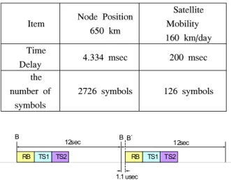
· Operability for a frame duration (12 seconds) An appropriate guard interval is necessary to avoid collision with another burst because the delay from satellite to node is different depending on the node position and mobility. At the uplink initial ranging, the guard interval should reflect the maximum delay according to the beam coverage. The time drift according to the movement of the satellite and node must be considered in the design of the guard interval of TB. The time delays according to the node position and the satellite mobility are shown in Table I.
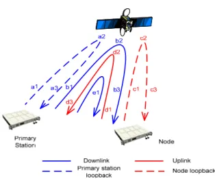
When a node moves at 100 km/h, it moves about 333 m during 12 seconds, single frame duration, and it means the delay of 1.1 msec occurs. The delay is almost one symbol duration at 629 ksps and causes severe performance degradation. The effect of this time delay is shown Fig 1. So, we design the frame structure as the primary station transmits 20 RBs in a frame to have the delay of less than 5% of the symbol duration.
Item Node Position 650 km
Satellite Mobility 160 km/day Time
Delay 4.334 msec 200 msec
the number of
symbols
2726 symbols 126 symbols Table 1. Time delays according to node position and satellite mobility
RB TS1 TS2 RB TS1 TS2
12sec 12sec
1.1 usec
B B B’
Fig. 1. Time drift according to the node mobility of 100km/h
Then it transmits an RB at every 0.6 seconds and the time drift between RBs is less than 3.5% of the symbol duration.
When a node moves at the speed of 100 km/h, the Doppler frequency shift of 717 Hz occurs at the carrier frequency. And frequency offsets also occur depending on the accuracy of reference clock. The frequency offset caused by oscillator is 650.5 Hz when we use GPS clock source and 2,265 Hz when we use local clock with oven controlled crystal oscillator (OCXO) source, and total frequency offsets of the network in each case are 2,359 Hz and 3,974 Hz respectively.
With the frame and burst structure designed from above consideration, all nodes in an operational radius of 650 km can achieve downlink and uplink synchronization without any collision and the node on the move at the speed of 100 km/h can receive data without any effect of time shift and Doppler shift.
Ⅲ. Synchronization Process using RB
The initial synchronization process using a RB
starts with downlink synchronization and then
performs uplink acquisition based on the
synchronous downlink. In addition, to utilize the
algorithm using a transmission pattern, the time
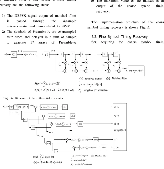
synchronization is necessary to be performed prior to the frequency and phase synchronization. Fig. 2 shows the initial synchronization process for downlink and uplink, and Fig. 3 explains signal delay and resulting compensation in downlink synchronization process. Because the feeder link delay between primary station and satellite and the mobile link delay between node and satellite are long, primary station and node adjust the transmission time based on the transmission time of satellite. And due to the motion of the satellite, the delay between primary station and satellite changes and thus the primary station should transmit RB after adjusting the transmission time.
To do this, the satellite loopback function such as a1~a2 in Fig. 2 is required. Also, nodes should acquire downlink time synchronization using the RB which is transmitted from the primary station and relayed by a satellite.
Through this downlink synchronization, nodes can obtain uplink transmission time as well as the information on downlink synchronization.
3.1. Frame Synchronization
In the initial synchronization process the first course we must do is to acquire frame synchronization. The frame synchronization is the process of searching for preambles and finding the starting position of the frame and burst. In order to reduce the acquisition time, all bursts are designed to include the same preamble. In the initial acquisition, assuming the maximum frequency offset of 25 kHz, the preamble is transmitted by differential coding scheme and uses PN sequence with good auto-correlation property.
After matched filtering, differential correlation between the signals oversampled four times and the first 300 symbols of the Preamble-A is performed in 2 samples unit. We can figure out the fact that the autocorrelation using differential decoding is robust against the effects of frequency offsets and phase offsets from the equation below
[3-6]
Fig. 2. Initial synchronization process for downlink and uplink
Fig. 3. Delay compensation in downlink synchronization process
≈∙
arg max
(1) where
is a received signal,
is already known signal,
is the number of preamble,
are individual phase offsets of
th,
th sample using DBPSK, and
is the phase which is rotated by the satellite link channel.
The implementation structure of the differential
) (t y h(t)
/2 T
T
) (t
y h(t)
) ( ) (k⋅x*k+4 x
* Np
c c*Np−1 c*Np−2 c*2 c1*
| ) (
| max
^ arg
q R q= q
Np
) (m R
T T T T
) ( )
(m c*zm k
R p
N
k k 2
1
+
⋅
=
∑
=
) ( ) (
)
(m x* m k xm k z = +2 −2 ⋅ +2
)) ( ( max arg m Rm /4
T
Fig. 4. Structure of the differential correlator
) (t
y h(t)T/4x(k)⋅x*(k+4) 1,...Np c c
/4 T
4 / T
/4 T
/4 T )
(m z
) ( ) (m c*zm k
R p
N
k k⋅ +
=∑=
−4 1
) ( ) (m c*zm k
R Np
k k⋅ +
=∑=
−3 1
) ( ) (m c*zmk
R p
N
k k⋅ +
=∑
− = 1 2
) ( ) (m c*zm k
R p
N
k k⋅ +
=∑
+ = 1 2
) ( ) (m c*zm k
R Np
k k⋅ +
=∑
+ = 1 4
)) ( ( max
arg Rm
m
) ( 8− R
(7) R
) ( 6− R
) ( 7− R
(8) R
) (t
y h(t)
| ) (
| max
^ arg q R q= q
Np
) ( )
(m c*zm k
R p
N
k k 4
1 ⋅ +
=∑
=
) ( ) ( )
(m x*m k xm k z = +4−4⋅ +4
Fig. 5
.
Structure of the coarse symbol timing recoverycorrelator is shown in Fig. 4. To reduce hardware resources in implementation, the signal is decimated to
.
3.2. Coarse Symbol Timing Recovery
Although a frame synchronization is performed with the first 300 symbols of Preamble-A, a coarse symbol timing recovery is performed with all symbols of Preamble-A. This is possible because the coarse symbol timing recovery uses 17 serial-correlators unlike the frame synchronization which uses parallel-correlator such as matched filter
[7]. The coarse symbol timing recovery has the following steps:
1) The DBPSK signal output of matched filter is passed through the 4-sample auto-correlator and demodulated to BPSK.
2) The symbols of Preamble-A are oversampled four times and delayed in a unit of sample to generate 17 arrays of Preamble-A
samples.
3) Each array is lined up at -8/4, -7/4, ..., 6/4, 7/4, 8/4 symbol point based on the starting point detected in frame synchronization process.
4) BPSK samples are multiplied by Preamble-A samples and then combined in a unit of the length of Preamble-A at the serial-correlator block.
5) The outputs of serial-correlators are indexed in order of R(-8), R(-7), ..., R(6), R(7), R(8).
6) The maximum value of the indexes is the output of the coarse symbol timing recovery.
The implementation structure of the coarse symbol timing recovery is shown Fig. 5.
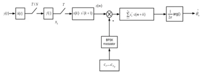
3.3. Fine Symbol Timing Recovery
fter acquiring the coarse symbol timing
synchronization, fine symbol timing recovery is performed to improve decoding performance of broadcasting information in RB. The received signal passed through a matched filter has a cyclo-stationary characteristic. So, after initial synchronization, symbol timing recovery can be done by a square-law nonlinear (SLN) method which is a non-data aided (NDA) timing recovery method
[8], [9]. The process of the SLN method is shown in Fig. 6. The estimation of
is
(2)
where
,
is symbol duration and
(3)
where
denotes the sample index, a unit of
, and
denotes the number of guard samples and Preamble-A samples.
3.4. Initial Frequency Synchronization
The initial frequency synchronization block is performed with all symbols of Preamble-B and can estimate the frequency offsets of up to 25 kHz through auto-correlation between constant symbol intervals preambles. The frequency offsets are estimated by converting a phase rotation value into an angle. The phase rotation value is obtained from performing auto-correlation between DBPSK modulated Preamble-B symbols and D symbols delayed Preamble-B symbols. And we use D as 6 to estimate the frequency offsets of up to 25 kHz
[10]. The initial frequency offsets estimation block is shown in Fig. 7.
3.5. Initial Phase Synchronization
The estimated frequency offsets of RB are compensated in the next burst. The frequency offsets which exist in BCCH data are converted to the common phase error because the BCCH data is DBPSK modulated symbol stream. To remove this common phase error in RB, the
common phase estimation is performed with Preamble-B symbols in RB and applied to the BCCH data in RB. The common phase offset estimation block is shown in Fig. 8.
( )
h n ⋅2 4∑kL=−01r ek2 −2πk/4 2−π1arg( )X
τ
drk X
Fig. 6. Process of the SLN method
) (t
y h(t) f(⋅) arg()
πD 2
∑−= + 1
−
D N
k rkDrk
D
N 1
1 { *}
4 / T
xk
) (t
y h(t)
^
f0
ck rk
T
Fig. 7. Block diagram of the initial frequency offset estimator
T ) ( ) (k⋅ kx* +1 x
Np
c c ,...1
) (m z
) (
*zm k
pc
N
k k⋅ +
∑=1 21πarg()
^
θ0
) (t
y h(t) f(⋅)
N T /
xk
Fig. 8. Block diagram of the initial phase offset estimator
Ⅳ. Simulation and Discussion
To evaluate the synchronization performance of the proposed frame structure for the satellite TDMA network, the complete physical layer simulator is implemented. Simulation results are composed of the frame synchronization, coarse symbol timing recovery, fine symbol timing recovery, initial frequency synchronization and phase synchronization.
In the first simulation, the frame
synchronization which finds the starting position
of the frame and burst is considered. The
performance of the frame synchronization is
closely related to how good auto-correlation
property of Preamble-A is in the low SNR
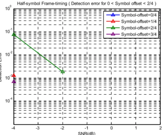
channel condition. Fig. 9 shows the ratio of the
-4 -3 -2 -1 0 1 2 10-4
10-3 10-2 10-1 100
SNR(dB)
Detection Error
Half-symbol Frame-timing ( Detection error for 0 < Symbol offset < 2/4 )
Symbol-offset=0/4 Symbol-offset=1/4 Symbol-offset=2/4 Symbol-offset=3/4
Fig. 10. Detection error rate of burst boundary at 25 kHz frequency offsets
-2 -1.5 -1 -0.5 0 0.5 1 1.5 2
0 20 40 60 80 100 120
Symbol offset R(x)
Preamble-A Correlation magnitude
Coarse Symbol Timing correlation
Fig. 11. Outputs of serial correlators in coarse symbol
timing recovery block
-4 -2 0 2 4 6
10-4 10-3 10-2 10-1 100
SNR(dB)
Detection Error Rate
Preamble length =400 symbol
adc유효비트=1bit adc유효비트=4bit adc유효비트=7bit adc유효비트=10bit adc유효비트=12bit
ADC bits=1bit ADC bits=4bits ADC bits=7bits ADC bits=10bits ADC bits=12bits
Fig. 12. Detection error rate of coarse symbol timing recovery at 25 kHz frequency
Fig. 9. Auto-correlation performance of Preamble-A at 25 kHz frequency offsets
maximum correlation value and the second large value of auto-correlation of Preamble-A, and it means the performance of auto-correlation for Preamble-A. Based on the fact that the starting position of the frame is generally deemed to be valid when the ratio of the maximum correlation value and the second large value is 3 dB or more, we can figure out that the Preamble-A which have the ratio of 7 dB at SNR = 0 dB has a good auto-correlation property in spite of low SNR and 25 kHz frequency offsets. The detection error rate curves of burst boundary based on sample-offset are shown in Fig. 10. The error rate is under 10
-2at SNR = -2 dB and no error occurs at SNR = 0 dB which is our target SNR. Because the frame synchronization is performed in a unit of a half symbol, we can know that the case of a half symbol offset shows the worst performance.
Fig. 11 shows the outputs of serial-correlators indexed R(-8), R(-7), ..., R(6), R(7), R(8) in the coarse symbol recovery block, and it means we can search the maximum value, R(0), easily though there are 25 kHz frequency offsets. The detection error rate curves of coarse symbol timing recovery according to the number of effective bits are shown in Fig. 12. If the number of effective bits of an ADC is more than 4 bits, there is no change in coarse symbol timing recovery performance.
The performance of the fine symbol timing recovery using a SLN method is shown in Fig.
13. We can know that fixed point and floating
point have the same performance and the root
mean square error (RMSE) of less than 3% at
SNR = 0 dB.
The performance of initial frequency offset estimation with 25 kHz frequency offsets and symbol offsets is shown Fig. 14. Because initial
Fig. 13. Performance of fine symbol timing recovery
Fig. 14. Performance of initial frequency offset estimation block at 25 kHz frequency offsets
frequency offset estimation is performed after the coarse symbol timing recovery which has a resolution of
, symbol offsets are less than 12.5% of the symbol duration. Thus, the initial frequency offset estimator has an estimation error of less than 700 Hz at SNR = 0 dB environment.
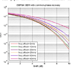
Fig. 15 shows BER curves of DBPSK with common phase recovery at 0~40 kHz frequency offsets. From this figure, we can know that the performance of DBPSK with 25 kHz frequency offsets has the performance degradation of less than 1 dB compared to the case of no frequency offset with common phase recovery processing.
This is quite satisfactory when considering the
amount of frequency offset.
Ⅴ. Conclusion
This paper discusses a frame structure of the
Fig. 15. Performance of common phase recovery at 0~40 kHz frequency offsets
satellite TDMA network and the synchronization method using a reference burst. To design the robust TDMA network appropriate to satellite communication, not only the position of the node and satellite but also the mobility is considered.
The frequency offsets of 25 kHz are reflected to all design elements as an important factor. To evaluate the synchronization performance of the proposed frame structure, the complete physical layer simulator is implemented. The timing, frequency and phase synchronization performance are simulated under various conditions. With the proposed frame structure and synchronization method, our satellite TDMA network can achieve robust synchronization under severe communication environments.
References
[1] Kamilo Feher, Digital Communication -
Satellite/Earth station Engineering,Prentice-Hall, 1983.
[2] ETSI EN 301 790 V14.1 “Digital Video
Broadcasting (DVB); Interaction channel for
satellite distribution systems,” Sep. 2005 [3] J. J. Spiker Jr., Digital Communication by
Satellite, Englewood Cliffs, NJ: Prentice-Hall,
1977.
[4] B. Sklar, Digital Communications by Satellite, Englewood Cliffs, NJ: Prentice-Hall, 1988.
[5] R. A. Scholtz, “Frame synchronization techniques,” IEEE Trans. Commun., vol.
COM-28, pp. 1204-1212, Aug. 1980.
[6] Z. Y. Choi and Y. H. Lee, “Frame synchronization in the presence of frequency offset,” IEEE Trans. Commun., vol. 50, no. 7, pp. 1062-1065, Jul. 2002.
[7] W. Zhuang, “Noncoherent hybrid parallel PN code acquisition for CDMA mobile communications,” IEEE Trans. Veh. Technol., vol. 45, no. 4, pp. 643-656, Nov. 1996.
[8] M. Oerder and H. Meyr, “Digital Filter and Square Timing Recovery ," IEEE Trans.
Commun., vol. 36, no. 5, pp. 605-612, May
1988.
[9] J. Wang and J. Speidel, “16QAM symbol timing recovery in the upstream transmission of DOCSIS standard," IEEE
Trans. Broad., vol. 49, no. 2, pp. 211-216, June2003.
[10] F. Classen, H. Meyr and P. Schier, “An all feedforward synchronization unit for digital radio,” IEEE Proc. VTC, pp. 738-741, May 1993.
고 경 수
(Kyungsu Ko)
2006년 한국과학기술원 전기 및 전자공학전공 석사 2006년~2010년 한국과학기술
원 MMPC(Mobile Media Platform Center) 연구원 2010년 2월~현재 LIG넥스원
통신연구센터 선임연구원
<관심분야> 차세대 이동통신, 디지털신호처리
오 일 혁
(Il-Hyuk Oh)
1996년 단국대학교 전자공학과 공학석사
1996년~2012년 LIG넥스원 통신연구센터 수석연구원
<관심분야> 군 위성통신 시스 템, 전술 데이터 링크 모뎀, 초고속 모뎀, 디지털신호처리
유 연 상
(Youn-sang Yoo)
1992년 2월 단국대학교 전자 공학과 졸업
1997년 8월 단국대학교 전자 공학과 석사
1997년 7월~현재 LIG넥스원 통신연구센터 수석연구원
<관심분야> 군 위성통신, 위성 통신용 단말, 위성통신용 모뎀
오 상 균
(Sang Kyun Oh)
1978년 2월 경북대학교 전자 공학과 졸업
1978년 3월~현재 국방과학연 구소
<관심분야> 전자공학, 통신공 학
이 희 수