Three dimensional finite element analysis of the stress distribution around the mandibular
posterior implant during non-working movement according to the amount of cantilever
Ji-Man Park1+, Hyun-Joo Kim2+, Eun-Jin Park1, Myung-Rae Kim3, Sun-Jong Kim3*
1Department of Prosthodontics, Ewha Womans University, Seoul, Korea
2Private Practice, Seoul, Korea
3Department of Oral and Maxillofacial Surgery, Ewha Womans University, Seoul, Korea
PURPOSE. In case of large horizontal discrepancy of alveolar ridge due to severe resorption, cantilevered crown is usually an unavoidable treatment modality. The purpose of this study was to evaluate the clinical criteria for the placement of the aforementioned implant crown. MATERIALS AND METHODS. The mandible model with 2 mm thick cortical bone and cancellous bone was fabricated from CT cross-section image. An external
connection type implant was installed and cantilevered crowns with increasing offset of 3, 4, 5, 6, and 7 mm were connected. Vertical load and 30° oblique load of 300 N was applied and stress around bone and implant component was analyzed. A total of 14 cases were modeled and finite element analysis was performed using COSMOS Works (Solid works Inc, USA). RESULTS. As for the location of the vertical load, the maximum stress generated on the lingual side of the implant became larger according to the increase of offset distance. When the oblique load was applied at 30°, the maximum stress was generated on the buccal side and its magnitude gradually decreased as the distance of the offset load increased to 5 mm. After that point, the magnitude of implant component’s stress increased gradually. CONCLUSION. The results of this study suggest that for the patient with atrophied alveolar ridge following the loss of molar teeth, von-Mises stress on implant components was the lowest under the 30° oblique load at the 5 mm offset point. Further studies for the various crown height and numbers of occusal points are needed to generalize the conclusion of present study. [J Adv Prosthodont 2014;6:361-71]
KEY WORDS: Finite element analysis; Implant prosthesis; Cantilever; Stress distribution
INTRODUCTION
Since the osseointegration of titanium has been introduced for the first time by Brånemark,1 the implant has become one of the reliable dental surgical methods that can replace the traditional fixed dental prosthesis as a method of recov- ering a missing tooth, and subsequently has been used suc- cessfully for fully or partially edentulous patients.2 In order for the implant prosthesis to perform a long term function within the mouth, the implant material must be biocompat- ible. In addition, it is important in terms of the biomechan- ics to design prosthesis that can adequately distribute stress generated upon the occlusion load within the limit of the load support capability of the supporting bones around the implant and the prosthesis.3
Corresponding author:
Sun-Jong Kim
Department of Implant Dentistry, School of Medicine, Ewha Womans University, 911-1 Mok-5-dong, Yangcheon-gu, Seoul, 158-710, Republic of Korea
Tel. 82 2 2650 5631: e-mail, [email protected]
Received 27 January, 2014 / Last Revision 10 June, 2014 / Accepted 16 June, 2014
© 2014 The Korean Academy of Prosthodontics
This is an Open Access article distributed under the terms of the Creative Commons Attribution Non-Commercial License (http://creativecommons.
org/licenses/by-nc/3.0) which permits unrestricted non-commercial use, distribution, and reproduction in any medium, provided the original work is properly cited.
This work was supported by the Ewha Womans University Research Grant of 1-2011-1684-001-2.
+ Ji-Man Park and Hyun-Joo Kim equally contributed to the works described in this manuscrpt.
In the cases of fully or partially edentulous patients, prosthetic recovery using implants supplements and replac- es partial and full dentures, and improves masticatory and retention forces, leading to the increase in patients’ satisfac- tion. Accordingly, the demand of the implant has been increasing even among patients with poor bone quality and quantity that restricts the installation of the implant.
However, since an alveolar bone frequently shrinks due to the long term full edentulism or the periodontal disease and generally in such cases, maxilla and mandible tend to be resorbed medially and laterally, respectively, the discrepancy in the positions of alveolar bone between maxilla and man- dible results, and subsequently it is often difficult to make normal occlusion.
Stress generated on the implant and nearby supporting tissues by occlusion force has a significant impact on suc- cessful osseointegration.4,5 Since the occlusion force is transmitted through the implant to bones upon masticating, the distribution of stress of the occlusion load and the bio- logical response of the body such as the regeneration of the bone can be important factors after implantation. Also, as the osseointegrated implant contacts the alveolar bone and does not allow even minute movement, most of stress concentrates on the alveolar crest. Subsequently, such con- centration of excessive stress will result in the osteoclasis (bone resorption) and may further lead to the failure of the implant prosthesis.6 Therefore, to increase the success rate of the implant, the resorption of surrounding bone needs to be taken into consideration, and for this purpose, it is important to consider stress generated on the surrounding supporting tissues. It has been shown that the excessive load on the implant could bring about the marginal bone resorption of the already osseointegrated implant or the loss of its osseointegration.7,8 Accordingly, when planning a treatment, there must be a careful consideration in order to distribute the load generated in the mouth adequately through the implant to the supporting bones.9
The implant may fail due to the poor hygiene in the mouth, biomechanical elements, bone quality and quantity, and the clinical status of patients. The bone quality and quantity of the implant site are significantly important fac- tors that affect the outcomes of the treatment, and the dis- tribution of stress generated on bones supporting the implant depends on the biomechanical properties of the surrounding bones.10,11 If a top down treatment plan is applied, which installs the implant at the location and angle that can complete the most ideal prosthesis according to the prosthetic-driven implant dentistry, the location of the implant may not be the center of the residual alveolar bone.
Although various bone graft techniques must be used in order to produce the prosthesis with the ideal shape, it is not easy to use such surgical methods in clinical settings.
When a tooth is lost, the width and height of the alveo- lar ridge are reduced, which has been reported for long.
Tallgren12 has shown through a long term radiological study on patients with a full denture that the mandibular alveolar ridge displayed 4-fold higher resorption compared to that
of the maxilla, and suggested that since the maxillary and mandibular alveolar ridges were resorbed medially and lat- erally, respectively, the aspect of class III crossbite has been frequently observed. Also, Atwood and Coy13 have reported the resorption rate of the alveolar ridge through radiologi- cal cephalometric analysis, and the result was similar to that of Tallgren.12
If the alveolar bone shrinks due to the prolonged peri- od of edentulism or periodontal problem and subsequently the resorption of the alveolar bone is severe, there are many cases that the implant needs to be installed on the location deviated from the ideal position. In such cases, the implant prosthesis involving cantilevers extending more to the buccal or lingual side is made and due to the bending moment generated by the presence of the cantilever that supports the load, the higher stress than that resulting from the actual load on the implant may be generated.14 Stegaroiu et al.15 has reported that the mesiodistal cantilever model needed to be avoided since it displayed substantially large increase in stress in every case, and Rangert et al.16 has shown that the bending moment in the mesiodistal cantile- ver model was generated more than two fold compared to the stiffened model. Biomechanical overload may lead to the failure of the implant treatment. To avoid the biome- chanical overload, there is a tendency that the cantilever shorter than the theoretical length required for the struc- ture, aesthetics, and function is used.14
Finite element analysis (FEA) is a method of an engi- neering analysis using the finite element method (FEM), a type of a numerical analysis. Thus, the numerical analysis of various engineering problems is performed using com- puter operating software (FEM program) developed on the basis of the theoretical system of the finite element meth- od. The finite element analysis is a method of analyzing parts or assembly to confirm the performance of a product in the engineering field. The FEA process includes making a solid model, calculating the response of the structure (deformation, stress) by generating finite element models in relation to the solid model and the defining the use envi- ronment (boundary condition, load condition), and finally showing these by a diagram. As the pre-process, a solid model is prepared, followed by the generation of a FEM model. As the solver process, finite element equations are established and solved, and in the post-process, the analysis result is processed and illustrated in the form easy to under- stand. Since Weinstein et al.17 used the finite element analy- sis in the implant dentistry for the first time in the dental field in 1976, it has been frequently used to analyze stress on surroundings of the implant, and the accurate applica- tion of the FEA has been possible owing to the continuing research. However, such FEA is the qualitative analysis that does not give the level of stress that may lead to the bone resorption and reformation, and therefore has significant limitations in terms of quantitative evaluation.
In this study, the stress distribution generated on the cortical bone, the cancellous bone, and the implant fixture, abutment and screw was observed using the 3-dimensional
finite element method for the 2 cases that the vertical loads were applied to the central fossa and the oblique loads were applied to the lingual cusp at 30° with a crown that had the increased lingual side during the non-working movement, and discussed the implication.
MATERIALS AND METHODS
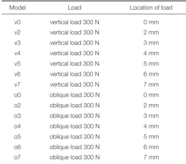
In this study, the modeling was based on the missing seg- ment of the right posterior mandible. A mandible block model was fabricated to have a regular shape with the height of 23 mm, mesiodistal width of 20 mm, the maxi- mum buccolingual width of 15 mm and the uniform thick- ness of the cortical bone by scanning bones in the area of right molar teeth using a CT and extending this shape in the direction of the cross-section. The mandible model consisted of the cortical bone and the cancellous bone, modeled in a simple shape to set a uniform thickness of the cortical bone at 2 mm. Crown was modeled to have a dimension of the height of 10.5 mm, the mesiodistal width of 10 mm, and the buccolingual width of 13 mm, which was extended in the lingual direction by 4 mm to ensure the application of offset loads of 2, 3, 4, 5, 6, and 7 mm on the lingual side. The top occlusal plane was modeled to a shape of a simple cusp. The implant was modeled by measuring the US II system (Osstem Implant, Pusan, Korea) that is an external type implant with the dimension of the 5.0 mm diameter and the 11 mm length. All models used in this study were generated using SolidWorks (DS SolidWorks Corp., Waltham, MA, USA), a commercial 3-dimensional CAD.The modeling was performed such that there was no choice but to add lingual offset to the mandibular implant crown where the resorption of the maxillary buccal and mandibular lingual alveolar bone was severe. Firstly, Model v0 was assigned to the case that the vertical load of 300 N was applied on the center of the implant, followed by Models v2 to v7 corresponding to the vertical loads offset to the lingual side at 2, 3, 4, 5, 6, and 7 mm, respectively.
Secondly, Model o0 was assigned to the case that the oblique load of 300 N at 30° which can be intermittently applied during non-working movement was applied on the center of the implant, and likewise, Models o2 to o7 were assigned to the oblique loads offset to the lingual side at 2, 3, 4, 5, 6, and 7 mm, respectively. Together, a total of 14 cases were modeled (Table 1).
The finite element analysis was carried out using COSMOSWorks (DS SolidWorks Corp., Waltham, MA, USA) and finite elements applied here were generated by the 10-node tetrahedral quadratic solid element. In the result of the finite element analysis, since the maximum stress might be varied depending on the size of finite ele- ments, the size of basic elements was set to be 1 mm con- sidering the convergence according to the size of elements, and fine elements with the size of 0.3 mm were used for the implant structure, and its surrounding cortical and can- cellous bones to increase the analytical accuracy. The finite
elements of bone formed detailed mesh of the implant connection area where stress was concentrated. Here, the shape of the screw at the fixture was transformed in con- sideration of the axis symmetry without losing its screw- like form, and integrated into the mesh. Also, the symmetry was taken into consideration by removing the cutting edge of the fixture and the alignment surface of the abutment (Fig. 1, Table 2).
Main material properties of the cortical bone, cancel- lous bone, fixture, abutment, screw, and crown used for the finite element analysis in this study such as the elastic mod- ulus and Poisson’s ratio were obtained on the basis of the previous researches18-21 and shown in Table 3.
Table 1. Experimental design in this study
Model Load Location of load
v0 vertical load 300 N 0 mm
v2 vertical load 300 N 2 mm
v3 vertical load 300 N 3 mm
v4 vertical load 300 N 4 mm
v5 vertical load 300 N 5 mm
v6 vertical load 300 N 6 mm
v7 vertical load 300 N 7 mm
o0 oblique load 300 N 0 mm
o2 oblique load 300 N 2 mm
o3 oblique load 300 N 3 mm
o4 oblique load 300 N 4 mm
o5 oblique load 300 N 5 mm
o6 oblique load 300 N 6 mm
o7 oblique load 300 N 7 mm
Table 2. Number of elements and nodes used in this study
Model Nodes Element
cortical bone 37,971 26,409
cancellous bone 78,800 54,972
fixture 96,955 54,972
abutment 12,727 8,943
screw 23,376 16,896
crown 12,513 9,233
Total model 262,243 189,850
Although actual bone displays different properties in the direction of x-, y-, and z- axes, respectively, and the bone quality (D1 - D4) is also different depending on the location, the isotrope was assumed such that physical prop- erties of the material were assumed to be identical in 3 directions to simplify the analytical model. Furthermore, the plasticity of the implant material was not considered but the linear elasticity was taken into consideration. Bone and the thread of the screw of the implant were presumed to be bonded to each other on the basis of the premise of the complete osseointegration.
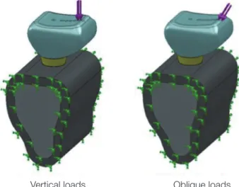
Two load conditions were employed for the analysis: 1) the vertical load was applied to the center of the implant, which considered the case that the vertical occlusal force was applied. 2) The oblique load at 30° from the lingual to buccal side was applied to the lingual cusp, which consid- ered the non-working movement of the mandible or the
lateral elements of the force exerted by the slope of the cusp. Therein, the magnitude of the loads was 100 N respectively, and a total of 300 N. In addition, if the load was applied to a particular point, a singular point where extraordinarily large stress is generated might emerge and subsequently it was designed that the distributed load would be exerted on the circular area with the diameter of 0.5 mm.
As for the boundary condition, since the principal aim of this study is to observe the distribution of stress accord- ing to the distance of the load from the center of the installed implant, the degrees of freedom of the bottom part of bone in the Ux, Uy and Uz directions were restrict- ed (Fig. 2).
As for the stress result, efficient stress was represented using the stress contour plot.
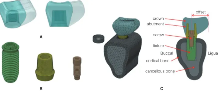
Fig. 1. 3D models used in this study. (A) Implant prosthesis with various level of lingual cantilever, (B) FE mesh of external connection type implant system, (C) isometric and sectional view of 3D model.
A
B C
crown abutment screw
fixture
Buccal Ligual
offset
cortical bone cancellous bone
Table 3. Material properties in this study
Geometry Material Elastic modulus
(GPa) Poisson's ratio Yield strength
(MPa)
Ultimate tensile strength (MPa)
Fixture CP Ti Grade4 105.00 0.34 590 660
Abutment CP Ti Grade4 104.00 0.34 450 520
Screw Ti Alloy 113.00 0.342 795 860
Cortical bone - 13.70 0.3 - -
Cancellous bone - 1.37 0.3 - -
Gold Crown Gold 100.00 0.35 - -
RESULTS
This study considered a total of 14 models, with 7 models of the vertical load applied upon the central fossa of the tooth and 7 models of the oblique load applied upon the lingual cusp tip according to the load conditions. Since the created finite element model is symmetrical relative to the central cross-section in the mesiodistal direction, stress data were obtained by averaging maximum stress values of 2 implant sites.
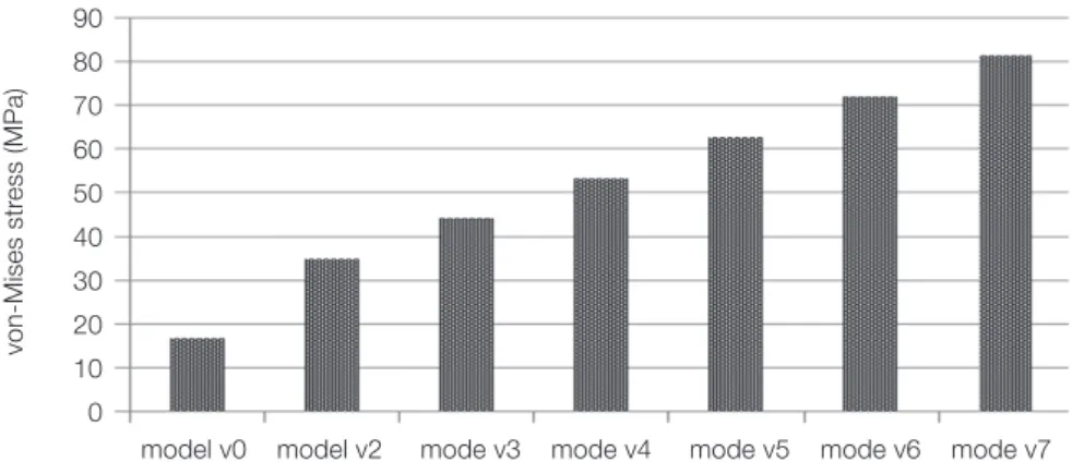
As the location of the vertical load was offset by 1 mm each time in the lingual direction, stress upon the cortical bone increased linearly in proportion to the distance of the offset load and that upon the implant increased linearly as well. On the other hand, in case that the location of the oblique load was offset by 1 mm each time in the lingual direction, stress upon the cortical bone gradually became smaller, and nearly uniform compressive stress was shown when it was offset by 7 mm. However, when the location of the oblique load was offset by up to 4 mm from the cen- ter of the implant, strong compressive stress appeared on the buccal side of the implant and its magnitude decreased.
On the contrary, when the offset distances were 6 and 7 mm, strong compressive stress was generated on the lingual side, and the magnitude of stress became larger as the dis- tance increased. Therefore, the smallest stress was generat- ed at the offset distance of 5 mm in the case of the oblique load (Table 4).
For the stress around the cortical bone under vertical load, uniform compressive stress was generated at the upper cortical bone where the implant fixture was installed in case that the vertical load was applied upon the center of the implant (Model v1). When the vertical load was offset by 1 mm each time in the lingual direction from the center of the implant, the clockwise bending moment was gener- ated and compressive stress was shown at the upper lingual side of the cortical bone around the implant. Also, tensile stress was shown in the opposite direction (Fig. 3 and Fig.
4). For the stress around the implant system under vertical load, the distribution of stress was shown to be similar to the pattern of stress applied upon the cortical bone for each model and loading condition. Uniform compressive stress appeared in the longitudinal direction of implant fix-
Table 4. Summary of the maximum von-Mises stress in this study (MPa)
Model Cortical Cancellous Implant Abutment Screw
v0 16.79 1.29 13.95 14.72 12.87
v2 34.73 1.47 38.76 42.86 25.17
v3 44.02 1.57 51.71 57.61 33.44
v4 53.30 1.67 64.77 72.39 41.68
v5 62.57 1.80 78.09 87.19 49.90
v6 71.87 1.96 90.20 102.31 58.08
v7 81.23 2.09 104.94 117.01 66.49
o0 73.51 2.00 63.54 70.68 62.71
o2 56.17 1.74 43.23 48.04 47.39
o3 48.12 1.61 34.81 37.01 40.02
o4 39.83 1.50 27.07 33.83 36.06
o5 31.98 1.39 20.42 34.42 36.53
o6 24.80 1.31 25.58 35.09 37.13
o7 15.68 1.25 37.94 37.49 37.84
Vertical loads Oblique loads Fig. 2. Loading condition and boundary condition. Three points of 100 N each were applied evenly forming the circular area with the diameter of 0.5 mm.
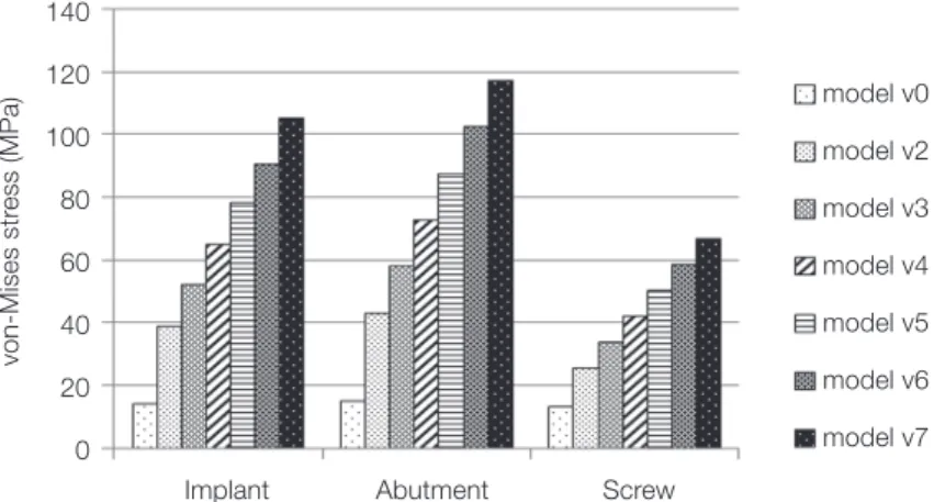
ture, abutment, and screw when the vertical load was applied upon the center of the implant (model v0). When the vertical load was offset by 1 mm each time in the lingual direction from the center of the implant, the clockwise bending moment occurred. Subsequently, strong compres- sive stress was generated on the lingual side of the connec- tion area of the implant fixture, abutment, and screw while tensile stress appeared in the opposite direction. As the location of the vertical load was offset by 1 mm each time, stress increased linearly in proportion to the distance of the offset load (Fig. 5 and Fig. 6).
For the stress around the cortical bone under oblique load, strong compressive stress was generated on the buccal side of the upper cortical bone around the implant when the oblique load was applied on the center of the implant (Model o0). Stress was gradually reduced when the oblique load was offset by 1 mm each time to the lingual direction from the center of the implant, and the nearly uniform compressive stress was generated in the case of the offset load applied at 7 mm from the center (Fig. 7 and Fig. 8).
For the stress around the implant system under oblique load, it was shown that strong compressive stress was gen- erated on the buccal side of the implant fixture, abutment and screw, and its magnitude decreased when the location
of the oblique load was offset by up to 4 mm from the cen- ter of the implant. When the distance where the offset load was applied was 6 and 7 mm, on the contrary, compressive stress was generated on the lingual side, and the magnitude of the stress became larger with the increasing distance.
The smallest stress was observed when the distance of the offset load was 5 mm (Fig. 9 and Fig. 10).
DISCUSSION
For successful implant prosthesis, the occlusal force applied must be distributed effectively by the implant and transmit- ted to bone. Sertgöz et al.22 and Yokoyama et al.23 have reported that when 2 implants were installed and cantilever- fixed prostheses were placed, increasing stress was applied on the implant fixture and abutment gradually with the increase in the extension of the cantilever, and Iplikçioğlu et al.24 also have shown that when the cantilever prostheses were installed in the posterior mandible using the short implant, stress applied upon the implant became larger with the increase in the length of the cantilever.
The occlusal force (100 N - 565 N) with various magni- tudes and directions was assumed and applied in previous studies.25 However, since the occlusal force and stress are in
Fig. 4. Distribution of von-Mises stress around cortical bone under vertical load.
model v0 model v2 model v4 model v6
B L
von Mises (MPa)
10,000 9,000 8,000 7,000 6,000 5,000 4,000 3,000 2,000 1,000 0,000
Fig. 3. Maximum von-Mises stress around cortical bone under vertical load.
90 80 70 60 50 40 30 20 10 0
model v0 model v2 mode v3 mode v4 mode v5 mode v6 mode v7
von-Mises stress (MPa)
Fig. 5. Maximum von-Mises stress around implant components under vertical load.
140 120 100 80 60 40 20 0
Implant Abutment Screw
von-Mises stress (MPa)
model v0 model v2 model v3 model v4 model v5 model v6 model v7
Fig. 6. Distribution of the von-Mises stress around implant components under vertical load. (A) Implant fixture, (B) abutment, (C) screw.
model v0 model v2 model v4 model v6
von Mises (MPa)
von Mises (MPa)
von Mises (MPa) 10,000
9,000 8,000 7,000 6,000 5,000 4,000 3,000 2,000 1,000 0,000
10,000 9,000 8,000 7,000 6,000 5,000 4,000 3,000 2,000 1,000 0,000
10,000 9,000 8,000 7,000 6,000 5,000 4,000 3,000 2,000 1,000 0,000
B L B L
B L A
B
C
Fig. 8. Distribution of von-Mises stress around cortical bone under oblique load.
model o0 model o2 model o4 model o6
B L
von Mises (MPa) 10,000
9,000 8,000 7,000 6,000 5,000 4,000 3,000 2,000 1,000 0,000
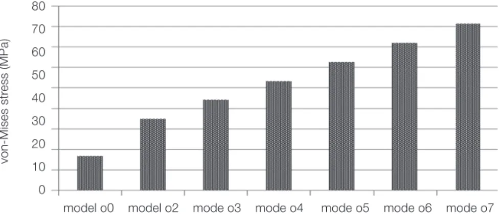
Fig. 7. Maximum von-Mises stress around cortical bone under oblique load.
80 70 60 50 40 30 20 10 0
model o0 model o2 mode o3 mode o4 mode o5 mode o6 mode o7
von-Mises stress (MPa)
Fig. 9. Maximum von-Mises stress around implant components under oblique load. In case of model o4, o5, and o6, the stress decrement at the implant was larger than that at the abutment and screw. And the model with the lingual
cantilever of 5 mm (model o5) was most affected.
80 70 60 50 40 30 20 10 0
Implant Abutment Screw
von-Mises stress (MPa)
model o0 model o2 model o3 model o4 model o5 model o6 model o7
a linear proportional relationship in which stress becomes larger with the increase in the occlusal force, and the princi- pal aim of this study is the relative comparison of stresses generated on the bone and implant depending on the dis- tance of offset loads, the direction of loads was set to be perpendicular to the central axis of the implant and tilted at 30° relative to the lingual cusp, and its magnitude was 300 N. In the case of the mesiodistal cantilever prosthesis, it has been shown in previous studies that the increase in stress became larger with the increase in the length of the cantilever. As such, this study was conducted with the assumption that stress applied upon the implant would increase in proportion to the rate of increase of the length of the lingual cantilever of prosthesis.
In the case that the vertical load was applied upon the
central axis of the implant (Model v0), since there was no horizontal component of force and the vertical load was identical with the central axis of the implant, the moment was zero and thus, uniform compressive stress was exerted around bone and the implant. In the case that the location of load was offset to the lingual side by the increment of 1 mm, although horizontal component of force did not exist, the clockwise bending moment was generated by the dis- tance between the vertical load and the central axis of the implant, and subsequently, compressive stress and tensile stress were exerted on the lingual and buccal sides, respec- tively. In addition, as the offset of the location of loads became larger, the moment and thereby the magnitude of stress also proportionally increased.
In the case that the oblique load was applied upon the central axis of the implant (Model o0), while the vertical Fig. 10. Distribution of the von-Mises stress around implant components under oblique load. (A) Implant fixture, (B) abutment, (C) screw.
model o0 model o3 model o5 model o7
von Mises (MPa)
von Mises (MPa)
von Mises (MPa) 10,000
9,000 8,000 7,000 6,000 5,000 4,000 3,000 2,000 1,000 0,000
10,000 9,000 8,000 7,000 6,000 5,000 4,000 3,000 2,000 1,000 0,000
10,000 9,000 8,000 7,000 6,000 5,000 4,000 3,000 2,000 1,000 0,000
B L B L
B L A
B
C
component of force is identical with the central axis of the implant, which did not generate the moment, the counter- clockwise bending moment was generated due to the hori- zontal component of force and thus compressive stress and tensile stress were exerted on the buccal and lingual sides, respectively, around the bone and the implant. In Model o5 where the location of the oblique load was offset to the lin- gual side by 5 mm, the counter-clockwise bending moment due to the horizontal component of force and the clock- wise bending moment due to the distance between the ver- tical component of force and the central axis of the implant occurred simultaneously, canceling each other, and subsequently, the least stress upon the implant was observed. Among the implant, abutment and screw, the effect of stress reduction was largest at the implant. It is because the implant comes in the direct contact with alveo- lar bone having low elastic modulus, and has the advantage of shock-absorbing against the vertical component of force. In Model o7 where the offset of the oblique load was larger than 5 mm, while the counter-clockwise bending moment was identical to those with the offset of 5 mm or less, the clockwise bending moment increased substantially, leading to the generation of tensile stress upon the buccal side and compressive stress upon the lingual side around the implant, which was opposite to Model o0, and the mag- nitude of stress increased compared to Model o5.
Therefore, the smallest stress was observed with the oblique load at 5 mm from the center.
When the vertical load was applied, compressive and tensile stresses appeared upon the cortical bone alternately in the direction of the implant, and compressive stress was dominant at the top of the cortical bone where the maxi- mum stress was generated. Weinberg26 suggested that most of force would be concentrated on the alveolar crest rather than being distributed through the surface of the implant, and similarly, Clelland et al.27 indicated that the maximum stress concentrated on the alveolar ridge of the cortical bone and stress would be decreasing as the cortical bone layer is becoming thicker. As the location of the vertical load was getting offset by 1 mm, stress would increase in linear proportion to the distance of the offset load since the bending moment on the bone increased. Just as Rangert et al.28 suggested in relation to the implant axis that the off- set load of the vertical occlusal force in the buccal direction resulted in the increased bending on the implant, it is pre- sumed that stress seemed to concentrate on the one side due to the generation of the bending moment.
Maximum stress was observed on the cortical bone at the area of implant’s first thread, and stress did not concen- trate on the cancellous bone, which is consistent with the results of Lum et al.21,25 Misch29 showed that most of stress concentrated on the cortical bone and the influence of the cortical bone was predominant in providing the initial sta- bility. In addition, he suggested that stress appearing on the cancellous bone was 10 fold less than that on the cortical bone and subsequently, the magnitude of the former had neither physical nor clinical significance. The maximum
stress on the implant appeared around the fixture connect- ing the abutment or the screw of the abutment.30-32
Since the implant model used in this study was a system of an external connection type, it could be seen that the maximum stress was generated on the bottom part of the abutment connected to the fixture. In the external connec- tion type, the external force exerted on the abutment is transmitted to the alveolar bone via the fixture connected to the abutment by a screw. At this moment, the maximum stress is generated on the connection area between the top of the fixture and the interior of the abutment. In the internal connection type, since the external force exerted on the abutment is transmitted by clamping force of the screw and the friction of the fixture collar, the maximum stress is generated in the interior of the fixture collar that is clamped with the abutment, and also on the screw of the abutment.
The finite element analysis requires sufficient under- standing of the simplification and assumption necessary to make a model, and it has limitations that it is difficult to reproduce the actual anatomical structure and the irregular- ly distributed bone quality, and the deep knowledge of mechanical engineering and extensive experience are need- ed for the good result. Recently, various imaging programs have been introduced that can configure 3D models by lay- ering image data obtained by CT scanning and use the dis- tribution of the bone quality accurately for the finite ele- ment model by utilizing x-ray absorption rates. These advances are expected to enable more realistic simulations in the future.
As stated above, when there are difficulties in making normal occlusion due to the severe resorption of the alveo- lar bone and subsequently, the buccolingual cantilever can- not be avoided, the cantilever designed to take the load off- set by 5 mm from the center of the implant is likely to min- imize a harmful load, assuming that the cusp angle of the antagonist teeth is 30°, and prosthesis height is 10.5 mm with the oblique load at 30° from the intermittent non- working movement. However, since the difference is expected to depend on the height of the prosthesis, addi- tional studies with the various clinical settings are necessary.
CONCLUSION
From the three dimensional finite element analysis of lin- gual cantilever implant prosthesis with increasing offset, the following conclusions could be drawn. As for the location of the vertical load, the maximum stress generated on the lingual side of the implant became larger as the distance of the offset load increased. When the oblique load was applied at 30°, the maximum stress was generated on the buccal side and its magnitude gradually decreased when the location of the load moved away until the clockwise and counter-clockwise bending moment became equal. After that point, the magnitude of stress increased gradually as the distance of loading point increased away from the implant center.
REFERENCES
1. Brånemark PI. Osseointegration and its experimental back- ground. J Prosthet Dent 1983;50:399-410.
2. Adell R, Lekholm U, Rockler B, Brånemark PI. A 15-year study of osseointegrated implants in the treatment of the edentulous jaw. Int J Oral Surg 1981;10:387-416.
3. Brunski JB. Biomaterials and biomechanics in dental implant design. Int J Oral Maxillofac Implants 1988;3:85-97.
4. Sones AD. Complications with osseointegrated implants. J Prosthet Dent 1989;62:581-5.
5. Williams KR, Watson CJ, Murphy WM, Scott J, Gregory M, Sinobad D. Finite element analysis of fixed prostheses at- tached to osseointegrated implants. Quintessence Int 1990;
21:563-70.
6. van Steenberghe D. A retrospective multicenter evaluation of the survival rate of osseointegrated fixtures supporting fixed partial prostheses in the treatment of partial edentulism. J Prosthet Dent 1989;61:217-23.
7. Quirynen M, Naert I, van Steenberghe D. Fixture design and overload influence marginal bone loss and fixture success in the Brånemark system. Clin Oral Implants Res 1992;3:104- 11.
8. Isidor F. Loss of osseointegration caused by occlusal load of oral implants. A clinical and radiographic study in monkeys.
Clin Oral Implants Res 1996;7:143-52.
9. Payant L, Williams JE, Zwemer JD. Survey of dental implant practice. J Oral Implantol 1994;20:50-8.
10. Lekholm U, van Steenberghe D, Herrmann I, Bolender C, Folmer T, Gunne J, Henry P, Higuchi K, Laney WR, Lindén U. Osseointegrated Implants in the treatment of partially edentulous jaws: a prospective 5-year multicenter study. Int J Oral Maxillofac Implants 1994;9:627-35.
11. Adell R, Eriksson B, Lekholm U, Brånemark PI, Jemt T.
Long-term follow-up study of osseointegrated implants in the treatment of totally edentulous jaws. Int J Oral Maxillofac Implants 1990;5:347-59.
12. Tallgren A. The continuing reduction of the residual alveolar ridges in complete denture wearers: a mixed-longitudinal study covering 25 years. J Prosthet Dent 1972;27:120-32.
13. Atwood DA, Coy WA. Clinical, cephalometric, and densito- metric study of reduction of residual ridges. J Prosthet Dent 1971;26:280-95.
14. Hutton JE, Heath MR, Chai JY, Harnett J, Jemt T, Johns RB, McKenna S, McNamara DC, van Steenberghe D, Taylor R, et al. Factors related to success and failure rates at 3-year fol- low-up in a multicenter study of overdentures supported by Brånemark implants. Int J Oral Maxillofac Implants 1995;10:
33-42.
15. Stegaroiu R, Sato T, Kusakari H, Miyakawa O. Influence of restoration type on stress distribution in bone around im- plants: a three-dimensional finite element analysis. Int J Oral Maxillofac Implants 1998;13:82-90.
16. Rangert B, Krogh PH, Langer B, Van Roekel N. Bending overload and implant fracture: a retrospective clinical analy- sis. Int J Oral Maxillofac Implants 1995;10:326-34.
17. Weinstein AM, Klawitter JJ, Anand SC, Schuessler R. Stress
analysis of porous rooted dental implants. J Dent Res 1976;
55:772-7.
18. Baik SH, Heo SJ. A three dimensional finite element analysis of stress distributions in implant-retained mandibular den- tures with various retainers. Doctor›s Thesis, Seoul National University, 2008.
19. Kenney R, Richards MW. Photoelastic stress patterns pro- duced by implant-retained overdentures. J Prosthet Dent 1998;80:559-64.
20. Benzing UR, Gall H, Weber H. Biomechanical aspects of two different implant-prosthetic concepts for edentulous maxillae. Int J Oral Maxillofac Implants 1995;10:188-98.
21. Lum LB, Osier JF. Load transfer from endosteal implants to supporting bone: an analysis using statics. Part one:
Horizontal loading. J Oral Implantol 1992;18:343-8.
22. Sertgöz A, Güvener S. Finite element analysis of the effect of cantilever and implant length on stress distribution in an implant-supported fixed prosthesis. J Prosthet Dent 1996;76:
165-9.
23. Yokoyama S, Wakabayashi N, Shiota M, Ohyama T. The in- fluence of implant location and length on stress distribution for three-unit implant-supported posterior cantilever fixed partial dentures. J Prosthet Dent 2004;91:234-40.
24. Iplikçioğlu H, Akça K. Comparative evaluation of the effect of diameter, length and number of implants supporting three-unit fixed partial prostheses on stress distribution in the bone. J Dent 2002;30:41-6.
25. Lum LB, Osier JF. Load transfer from endosteal implants to supporting bone: an analysis using statics. Part two: Axial loading. J Oral Implantol 1992;18:349-53.
26. Weinberg LA. The biomechanics of force distribution in im- plant-supported prostheses. Int J Oral Maxillofac Implants 1993;8:19-31.
27. Clelland NL, Lee JK, Bimbenet OC, Gilat A. Use of an axi- symmetric finite element method to compare maxillary bone variables for a loaded implant. J Prosthodont 1993;2:183-9.
28. Rangert B, Jemt T, Jörneus L. Forces and moments on Branemark implants. Int J Oral Maxillofac Implants 1989;4:
241-7.
29. Misch CE. Available bone and dental implant treatment plans. In Micsh CE (ed): Contemporary implant dentistry. 2nd eds. St Louis; MO; Mosby; 1999, p. 178-99.
30. Richter EJ, Orschall B, Jovanovic SA. Dental implant abut- ment resembling the two-phase tooth mobility. J Biomech 1990;23:297-306.
31. Borchers L, Reichart P. Three-dimensional stress distribution around a dental implant at different stages of interface devel- opment. J Dent Res 1983;62:155-9.
32. Lavernia CJ, Cook SD, Weinstein AM, Klawitter JJ. An analy- sis of stresses in a dental implant system. J Biomech 1981;14:
555-60.