Domain Switching and Crack Propagation of BaTiO
3Single Crystal in Different Environments
Kewei Gao†, Xianwu Zhao, Ruimin Wang, Lijie Qiao, and Wuyang Chu
Department of Materials Physics and Chemistry
University of Science and Technology Beijing, Beijing, 100083, China
The influence of a moist atmosphere on 90odomain switching under a sustained electric field, stress corrosion cracking of an indentation crack in water and an aggressive solution, and the relation between penetrating crack propagation and domain switching were studied using BaTiO3 single crystal. The results indicate that enlarging the domain switching zone and crack propagation could be facilitated by a moist atmosphere or an aggressive solution due to the indentation residual stress. A moist atmosphere exerts remarkable influence upon the polarization of BaTiO3 single crystal under a sustained electric field, and the surface energy of the c domain was much lower than that of the a domain. Domain switching ahead of a penetrating indentation crack tip was an essential requirement for crack propagation under constant stress.
Keywords : ferroelectric BaTiO3 single crystal, indentation crack, domain switching, stress corrosion cracking.
†Corresponding author: [email protected]
1. Introduction
BaTiO3 single crystal has been widely used because of its special physical properties. However, the low fracture toughness of BaTiO3 single crystal has led to equipment failure at very low stress.1) PbZr1-x TixO3 (PZT) ferro- electric ceramics and BaTiO3 could undergo stress corro- sion cracking (SCC) under constant stress in a moist at- mosphere, water, formamide and formaldehyde.2),3),4) On the other hand, the delayed fracture of PZT ceramics in a moist atmosphere under a sustained applied electric field could occur due to SCC,4),5) which was attributed to large stress concentration induced by domain switching caused by the electric field, leading to unhomogenous strain.6),7) The delayed fracture under an electric field or stress in a moist atmosphere could be attributed to the adsorption of water molecules, which reduced the surface energy, re- sulting in crack propagation.2),4),5),8) Serviced in an electric field, the failure of BaTiO3 single crystal would be related to both the environment and domain switching itself.
However, up until now, there have been no reports that focus upon the influence of the environment on domain switching under sustained stress and an electric field. In addition, it is not clear if BaTiO3 can undergo SCC, and the relationship between crack propagation and domain
switching is also unclear.
The aim of this study is to investigate if SCC can occur in BaTiO3 single crystal under indentation residual stress in a moist atmosphere; if water molecular absorption is an influence upon domain switching in BaTiO3 single crys- tal under a sustained electric field; the relationship between domain switching ahead of a penetrating crack tip and crack propagation under constant stress; and the influence of an aggressive solution on indentation crack propagation and its surrounding domain switching.
2. Experimental procedure
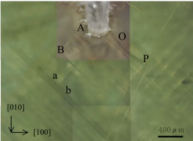
BaTiO3 single crystal, 5×5×1 mm3 in size, was poled along [001] (out-of-plane) or [100] (in-plane) directions, as shown in Fig. 1. Vickers indention was performed on the polished (001) surface, and the indent diagonals were aligned with [100] and [010] directions, respectively. The applied load was 0.98 N or 1.96 N for 20s. The sample surface and the domain structure were observed using a differential interference contrast (DIC) device and polar- ized light microscopy, respectively, and the observation results are shown in Fig. 2.
The sample was placed in a moist atmosphere right after the indentation test, and the propagation process of cracks from the indent corners was recorded. After the cracks arrested, the sample was immersed in water to determine
Fig. 1. BaTiO3 single crystal (a) poled in-plane (b) or out-of-plane (c)
(b)
20μm
(a)
Fig. 2. Vickers indent cracks on in-plane poled BaTiO3 single crystal
if the crack could propagate again. A polished surface of BaTiO3 single crystal was etched using 14% HCl+14%
HF+72% H2O (in volume percent) solution, and the in- dentation crack propagation and 90o domain switching zone enlargement due to etching were recorded.
Electrodes were attached to two side faces using silver paint, and a sustained electron field was applied to the sample along the [100] direction, as shown in Fig. 1b, and the domain switching was in situ observation by microscopy. Two copper plates were connected to the sam- ple's two surfaces as electrodes when the electric field was
Fig. 3. Schematic diagram of a constant loading device
applied along the [001] direction, as shown in Fig. 1c, and the domain switching on the sample surface could be observed after the applied electric field was removed.
Fig. 3 shows how to apply a load to a sample. A bulk WOL sample was used as a holder, and a BaTiO3 sample with a single-edge notch was inlaid on the notched end of the WOL holder. A strain gauge was glued to the BaTiO3 sample to record the strain while the BaTiO3 sam- ple was loaded through bolt A.
(a) t = 0
(b) t = 40h in air
(c) in water
a
b
a
b
a
b e
f
A
e
f
e
f
50μmB A C D
A
1B
1D
1C
1A
2B
2D
2C
2Fig. 4. Delayed propagation of unloaded indentation cracks in a moist atmosphere and deionized water
Fig. 5. c-a domain switching on the sample out-of-plane poled along the [001] direction in air with 2% RH under the applied electric field E = 224 V/mm along the [100] direction
3. Results
3.1 Delayed propagation of an indentation crack under indentation residual stress in a moist
3.1.1 Atmosphere and water
An unloaded indent with four cracks, A, B, C and D, emanating from the indent corners is shown in Fig. 4a.
The four cracks propagated to A1, B1, C1 and D1, re- spectively, after being kept in a moist atmosphere with a relative humidity of 20% for 40 h and then arrested, as shown in Fig. 4b. 45o domain bands could be seen, and crack A propagated across the domain band ab. When the sample was immersed in deionized water for another 40 h, the cracks propagated to A2, B2, C2 and D2, re- spectively, as shown in Fig. 4c. After that, the cracks did not propagate further.
3.2 Domain switching of BaTiO3 single crystal under a sustained applied electric field in a moist
3.2.1 Atmosphere
Two identical samples poled out-of-plane along the [001]
direction were put into air (2% RH) and a moist atmos- phere (92% RH), respectively. A 100 V/mm electric field along the [100] direction was applied to both samples and maintained for 24 h. No domain switching occurred on either sample surface. The applied electric field was then increased to 120 V/mm for another 24 h, and still no do- main switching occurred on either sample. Another 20 V/mm was then added to the applied electric field for 24 h, and this operation was repeated. When the applied elec- tric field reached 224 V/mm, c-a domain switching oc- curred, but only to the sample in air (2% RH). The non-switching sample in the moist atmosphere was trans- ferred to the air and a 224 V/mm electric field was applied.
After 24 h, all c domains switched to a domains.
An indent A on the sample surface poled along the [001]
direction is shown in Fig. 5a, with a magnified image in the bottom right corner. Cracks along the indent A corners were isotropy, which revealed that the observed surface of the sample in Fig. 5a was dominated by the c domain.
A sustained electric field of 224 V/mm was applied to the sample in air (2% RH) for 2 h, and some c domains
Table 1. Critical electric field for complete domain switching in dry or moist atmospheres during 24 hours
92% RH 70% RH 2% RH
c domain to a domain 300V/mm 250V/mm 224V/mm a domain to c domain 150V/mm 210V/mm
transferred to a domains, as shown in Fig. 5b, in which the bright line corresponds to a domains. a domains ini- tiated from two sides, moved to the center, and gradually became wider. The sample was kept in air for a further 12 h, as shown in Fig. 5c, and many a domains appeared.
After a further 10 h, the surface was full of a domains, indicated by a new indent B, shown in Fig. 5d, with typical anisotropy cracks along the indent corners. The magnified image in the bottom right corner of Fig. 5d is indent A, which illustrates that the cracks propagated, compared with indent A in Fig. 5a.
If the sample poled along the [001] direction was put into a moist atmosphere with 92% RH, it was only after the applied electric field was increased to 300 V/mm that all c domains switched to a domains. If the relative humid- ity of the moist atmosphere was 70%, the applied electric field for the complete switching was 250 V/mm. So, the critical applied electric field for all c domains to transfer to a domains on the sample surface poled along the [001]
direction increased with the relative humidity of the atmos- phere, as listed in Table 1.
Two of the same samples poled along the [100] direction were applied with an electric field along the [001] direction and put into air (2% RH) or a moist atmosphere (92%
RH), respectively. The applied electric field started at 100 V/mm, and 10 V/mm were added every 24 h. When the applied electric field increased to 150 V/mm for 24 h, the domain switching from a domain to c domain finished in the 92% RH moist atmosphere, while in air, the critical electric field was 210 V/mm. For the in-plane poled sam- ple, the critical electric fields for a-c domain switching in atmospheres with various relative humidities are also listed in Table 1.
3.3 The relationship between domain switching and crack propagation
As shown in Fig. 3, a single-edge notched sample was installed on a bulk WOL holder and in situ observed dur- ing loading. When the applied stress was 7 MPa, there was no change to the notch tip. When the applied stress increased to 20 MPa, a lot of domain switching bands appeared ahead of the notch tip. When the applied stress was increased to 32 MPa, the number of domain switching bands increased without any cracks initiating. After the
A
B P
O
a b
400μm [010]
[100]
Fig. 6. Domain switching ahead of the notch tip after cracks initiated
applied stress was increased to 47 MPa, the domain switching zone continually enlarged. At the same time, two penetrated cracks, AB and OP, initiated from the notch tip, as shown in Fig. 6.
The propagation process of crack OP in Fig. 6 is shown in Fig. 7. There was a bright domain switching area ahead of the crack tip, shown in Fig. 7a, b and c, which dis- appeared after 19 min, as shown in Fig. 7d, e and f. It is noted that a domain switching band existed at the crack tip during the whole crack propagation process, and moved ahead with crack propagation. For example, the domain switching band at position DE in Fig. 7d moved to position FG in Fig. 7e, accompanied by crack propagating after 7 min, and the domain switching at position HI in Fig.
7i moved to position JK in Fig. 7j after 1.4h. New domain switching bands nucleated at the rear of crack OP after the domain switching band at the crack tip moved forward with crack tip propagation. Some domain switching bands at the rear of the crack disappeared when the crack propa- gated, such as the band at position DE in Fig. 7d, which disappeared in Fig. 7i after 4h.
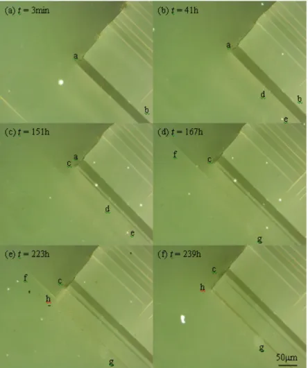
After the crack in Fig. 6 arrested, increasing the applied stress to 60 MPa again induced crack propagation to posi- tion a, as shown in Fig. 8a. Keeping the stress for 41h, the crack did not propagate, but a very thin domain switch- ing band ed appeared ahead of domain switching band ab, as shown in Fig. 8b. The domain switching band ed continually enlarged and reached the crack tip after 151h.
At the same time, the crack propagated from position a to position c, as shown in Fig. 8c. A new domain switching band "fg" nucleated ahead of the crack tip at 167h, as shown in Fig. 8d. This domain switching band became wider and disappeared at 223h when the crack propagated from position c to position h, as shown in Fig. 7e and 7f.
Fig. 7. Crack propagation accompanied by domain switching
Fig. 8. SCC crack propagation induced by the initiation and growth of domain switching bands
3.4 The effect of etching on the indent crack and the domain switching zone around the indent
Half of the sample in-plane poled along the [100] direc- tion was immersed in HCl+HF solution for 20s, and then eight indents were performed on each half part of the sam- ple, as shown in Fig. 9a. The length of every crack along the indent corner was measured, and then the whole sam- ple was immersed in the solution for 20s again, as shown in Fig. 9b. Changes in the length of the cracks were de- termined, and it was found that the average length of the cracks on the non-immersed part of the sample was X1
= 140 ± 17 μm, which increased to X3 = 216 ± 12 μm af- ter immersion, while the length value of X2 = 211 ± 26 μm for the cracks on the pre-immersed part of the sample increased to 221 ± 13 μm after further immersion. The measured results are listed in Table 2, which indicates that the aggressive solution could induce the indent crack on the surface with a domains propagating 50% in length,
1
10 3
6
9
2
5 7
4
P Q
11
12 14 15
13
A
(100)
B
(a)
100μm
1
2 3
4
5 6
9
7
10
11
12 13 14
P
15
Q
100μm
(b)
AB
Fig. 9. Eight indents on non-immersed or immersed parts of the sample (indent 8 and 16 were out of the image) (a), and the whole sample was immersed in the solution after indentation (b). PQ is the boundary between the non-immersed and immersed part
Table 2. Average length of cracks in various immersed conditions, μm
As indented Indented after immersed
Immersed after indented
Immersed twice
140 ± 17 211 ± 26 216 ± 12 221 ± 13
and there was no difference if the sample was pre-im- mersed or not.
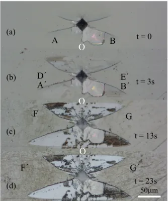
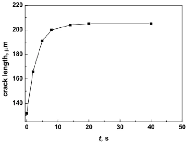
An indent crack shown in Fig. 10a was immersed in the solution for 3s, resulting in the enlargement of the domain switching zone and crack propagation, as shown in Fig. 10b. The 90o domain switching zone enlarged to D'OE', and the crack propagated from position A and B to position A' and B'. However, the crack tip which propa- gated along the domain switching zone did not reach the domain switching zone tips D' and E'. Following im- mersion for a further 10s, the domain switching zone en- larged again, especially the lower part of the zone from OFG to O'F'G', as shown in Fig. 10c. Immersion for a further 10s saw no remarkable changes in the domain switching zone and crack, as shown in Fig. 10d. Similar measurements were carried out using another twelve sam- ples, and the results indicated that the average length of cracks increased with immersion time and reached satu- ration values after 15s, as shown in Fig. 11.
50μm
(a)
A B
t = 0O
D΄ E΄
t = 3s(b)
B΄
A΄
O
F G
t = 13s (c)
O
G΄
F΄
t = 23s (d)
Fig. 10. Indent crack morphologies after immersion for different times
0 10 20 30 40 50 140
160 180 200 220
crack length, μm
t, s
Fig. 11. Variation in average crack length versus immersion time
4. Discussion
4.1 The delayed propagation of indent cracks under indentation residual stress in a moist
4.1.1 Atmosphere And Water
Just after an indent crack is unloaded, the stress intensity factor of the crack tip is equal to the fracture toughness of the material, KIC, and the drive energy for crack prop- agation is equal to the resistance. When the crack surfaces adsorb water molecules, the surface energy γ will de- crease to γSCC, resulting in the resistance to crack prop- agation reducing from 2γ to 2γSCC. The crack prop- agation energy induced by residual stress is:
Y
GI KI
2 2) 1 ( −ν
= (2)
where v is Possion's rate. For a brittle BaTiO3 single crys- tal, according to Griffith theory, the critical condition for crack propagation is:
Y
GI KI
2 2) 1 2γ = =( −ν
(3)
Since KI =0.0117dcPY3 ,9) for an unloaded indent crack,
03
2 2 2 2
2) 0.0117 (1 )
1 2 (
c
P d Y
KI ν
γ −ν = −
= (4)
where c0 is the initial length of the indent crack. When the surface energy decreases from 2γ to 2γSCC due to adsorbtion, the crack will propagate from c0 to c, then
3
2 2 2(1 ) 0117
. 2 0
c
P d
SCC
γ = −ν
(5) By combining Eqs. (4) and (5), then
3
3 0
c
SCC =c γ γ
(6) Substituting the data in Fig. 4 to Eq. (6), therefore
( ) 0.60
γ = γSCC humidair
, ( )=0.04 γ
γSCC water
(7) The result indicates that the surface energy of the sample in water is lower than that in air. Similarly in etching,
( ) 0.27 γ =
γSCC HCl
(8)
4.2 The effect of a moist atmosphere on the domain switching of a Batio3 single crystal under
4.2.1 A sustained electric field
Fig. 12 schematically illustrates the domain switching process from c domain to a domain. AG corresponds to the observed surface, and the poling direction is indicated by arrows. The original poling direction of the sample was [001]. After an electric field along [100] was applied, a domain along [100] direction appeared, such as α, γ, ε area in Fig. 12, while β, δ and ζ were c domain. The a-c domain boundary was 90o, inclined by 45o to the sam- ple surface. a-c domain switching caused a reduction of (1.01-1)/1 = 1% in height, so position C in Fig. 12 is lower than position D as 1% CD, i.e., ∠DCE = arctan (0.01)
= 0.6o. Due to this difference, lines AB, CD and EF were bright observed by the differential interference contrast method, and lines BC, DE and FG were dark. In fact, sub-domains existed on A, B and C domain walls in order to achieve the lowest domain wall energy.10)
The influence of a moist atmosphere on domain switch- ing under a sustained electric field can be related to water
Fig. 12. Schematic diagram of c-a domain switching
molecular adsorption. c domain surface adsorbs more wa- ter molecules than a domain because of water molecular polarity. Assuming ΔW is the energy necessary for an unit area poled in a vacuum, the work for the sample totally poled in a vacuum was EPsV = △WV, where E is the ap- plied electric field strength, Ps the saturated polarization strength, and V the volume of domain switch. After the water molecules were adsorbed on the sample surface, the changes in surface energy before and after the sample was poled are:
) )(
( 2 ) (
2 ) (
2 : a c
) )(
( 2 ) (
2 ) (
2 : c a
2 1 c ad a ad 2 a ad c ad 1 c ad a ad
2 1 c ad a ad 2 c ad a ad 1 a ad c ad
S S S
S
S S S
S
−
−
=
− +
−
→
+
−
−
=
− +
−
→
γ γ γ
γ γ
γ
γ γ γ
γ γ
γ
Then, the work done by the electric field will be,
) )(
( 2
) )(
( 2
2 1 c ad a ad s
h a c
2 1 c ad a ad s
h c a
S S WV
V P E
S S WV
V P E
−
− + Δ
=
+
−
− + Δ
=
→
→
γ γ
γ γ
Therefore,
) J/m ( 8 . 10 9
) 2 10 ( 4
10 10 0.21 10 ) 150 300 (
) ( 4
) ) (
(
2 6
9 3
2 1
switching s h
c a h
a c c
ad a ad
× =
−
×
×
×
×
×
= −
−
= −
−
−
−
→
→
S S
V P E γ E
γ
where Ps= 0.21 c/m2, S1 = 2×5 mm2, V = 1×2×5 mm3,in which Ps was calculated based on each atom's position in a tetragonal crystal lattice of a BaTiO3 single crystal:
Ba: (0,0,0), Ti: (2 1, 2
1, 2
1+0.0135), OI: (2 1, 2
1, 2
1+0.0250),
OII: (21, 0, 21- 0.0150), a = 0.3392 nm, c = 0.4036 nm.
4.3 The relationship between domain switching and crack propagation
Figs. 7 and 8 indicate that domain switching bands form ahead of the crack tip, which will induce crack propagation
when the bands grow and move close to the crack. So, domain switching is a necessary condition for crack pro- pagation.
5. Conclusions
(1) In a moist atmosphere or water, indentation residual stress can induce the delayed propagation of an unloaded indent crack in a BaTiO3 single crystal.
(2) A moist atmosphere has a remarkable influence upon the domain switching in a BaTiO3 single crystal under a sustained electric field, which could be attributed to sur- face energy reduction by water molecule adsorption.
(3) For an in-plane poled BaTiO3 single crystal, etching using HCl+HF solution before or after indentation could induce the indent crack to elongate 50% and the domain switching zone to enlarge upon the sample surface.
(4) A stress corrosion crack propagates when domain switching occurs ahead of the crack tip, i.e., domain switching is a necessary condition for stress corrosion crack propagation.
References
1. T. H. Hao, X. Gong, and Z. Suo, J Mech Phys Solids, 44, 23 (1996).
2. R. M. Wang, W. Y. Chu, K. W. Gao, Y. J. Su, and L. J. Qiao, Mater Letter, 58, 1811 (2004).
3. T. Y. Zhang, L. Q. Chen, and R. Fu, Acta materials, 47(14), 3869 (1999).
4. Y. J. Su, Y. Wang, W. Y. Chu, K. W. Gao, and L.
J. Qiao, Acta mater, 52, 3753 (2004).
5. Y. Wang, W. Y. Chu, K. W. Gao, Y. J. Su, and L.
J. Qiao, Appl Phys Lett, 82, 1583 (2003).
6. T. Zhu and W. Yang, J Mech Phys Solids, 47, 81 (1999).
7. Z. Suo and O. Curr, Solid State Mater Sci, 3, 486 (1998).
8. Y. Wang, W. Y. Chu, Y. J. Su, and L. J. Qiao, Mater Sci Eng, B95, 263 (2002).
9. G. R. Anstis, P. Chantikul, B. R. Lawn, and D. B.
Marshall, J Am Ceram Soc, 64, 533 (1981).
10. J. Munoz-Saldana, G. A. Schneider, and L. M. Eng, Surface Science, 480, L402 (2001).

![Fig. 5. c-a domain switching on the sample out-of-plane poled along the [001] direction in air with 2% RH under the applied electric field E = 224 V/mm along the [ 1 00 ] direction](https://thumb-ap.123doks.com/thumbv2/123dokinfo/5404311.218520/3.892.157.741.571.1039/domain-switching-sample-plane-direction-applied-electric-direction.webp)