3-D Coupled Analysis of Deformation of the Strip and Rolls in Flat Rolling by FEM- Part II: Application
H. J. Park, S. M. Hwang
(Received June 8, 2017 / Revised July 11, 2017 / Accepted July 17, 2017)
Abstract
A general approach is proposed for 3-D coupled FE analysis of the deformation of the strip and rolls in flat rolling. FE formulation, schemes for the treatment of contact occurring in a cluster of deforming objects, and the solution strategy are described in detail. The validity of the approach is examined through comparison with observed measurements. The approach is applied to the analysis of deformation in a four-high and six-high mill.
Key Words : Flat Rolling, Finite Element Method, Elastic-Plastic Deformation, Coupled Analysis, Contact Problem
1. 서 론
최근 압연 품질에 대한 소비자의 기대 욕구 증가 로 인해 압연으로 생산된 제품의 품질 향상에 대한 연구가 다방면에서 진행되고 있다 . 압연된 제품의 품질을 결정하는데 가장 중요한 요소는 정확한 판 프로파일 (strip profile)이다.
정확한 판 프로파일 예측을 위해 유한요소법을 활용하여 수학적 모델을 만들거나 압연 공정 과정 에 대한 현상을 분석하고 있다 . 과거에는 압연 공정 유한요소 해석을 판 혹은 롤을 개별적으로 해석하 였으나 [1~3] 압연 공정은 엄연히 판과 롤이 연계되 어 있는 문제 (coupled problem)이며 판과 롤을 연계시 켜 해석하는 것이 당연하다 .
‘유한 요소 법을 활용한 평판압연에서의 롤 판 연 계 해석 – Part I’에서는 새로운 유한 요소 접근 방법 에 대해 자세히 소개 하였다 .
Fig. 1 Geometries and boundary conditions selected for FE simulation of the elastic deformation of rolls in a six-high mill. Bite zone length = 12.36mm, total roll force = 1300ton. Young’s modulus = 205 GPa, Poisson’s ratio = 0.3, roll initial crown = 0
1. 포항공과대학교 기계공학과
# Corresponding Author: Department of Mechanical Engineering, POSTECH, E-mail: [email protected]
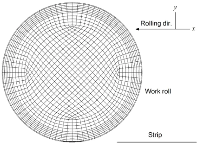
Fig. 2 The roll meshes used for the case with IMR shift
= 400mm
Fig. 3
s
distributions at WR-IMR and IMR-BUR interfaces, IMR shift = 0. The contact arc lengths are approximately 4.1 ~ 4.4mm, Stress Unit = GPa본 논문에서는 Part I에서 소개한 접근 방법을 실 제의 공정 조건에 적용시켜 유의미한 시뮬레이션 결과를 도출해 내고 이 결과를 실측치와 비교하여 이 접근 방법의 타당성을 증명 하고자 한다 .
2. 적용 1. 6단 압연기에 대한 탄성 해석
해석에 적용할 6단 압연기는 Fig. 1 과 같다. 여기 에서는 다중 접촉 문제에서 객체간의 변형에 초점 을 맞추고 있으므로 롤에 작용하는 힘은 판의 폭만 큼 일정한(uniform)힘을 받는다고 가정한다. 중간롤 (IMR)은 워크롤(WR)에 대하여 유형1 객체로 간주되 고 백업롤(BUR)은 중간롤에 대하여 유형1 객체로 간주 된다 . 계산 순서(computational hierarchy)에 따라 워크롤 → 중간롤 → 백업롤의 순서로 계산이 진행 된다 . 중간롤은 보통 실제 공정에서 이동(shift)되며
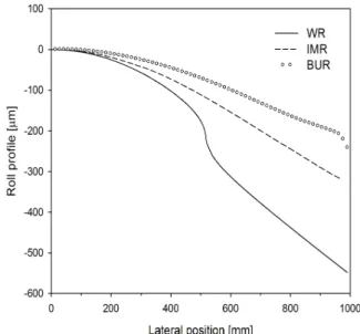
Fig. 4 The deformed roll profiles at the bottoms of WR, IMR, and BUR. IMR shift = 0
이 시뮬레이션에 사용된 격자는 Fig. 2와 같다.
각각의 롤에 사용된 격자의 개수는 110,000~
140,000개 이다. 워크롤과 중간롤, 중간롤과 백업롤 사이의 응력 분포는 Fig. 3과 같다. 이는 현재의 접 촉 문제(contact problem) 해석 방법이 탄성롤에 대하 여 효율적으로 적용되고 있음을 보여 준다 .
Fig. 4는 워크롤과 중간롤, 백업롤의 하부 프로파 일을 보여주고 있으며 워크롤은 압입 (indentation)에 가장 큰 영향을 받고 중간롤과 백업롤은 롤의 휘어 짐 (bending)에 큰 영향을 받고 있음을 알 수 있다.
3. 적용 2. 판에 대한 탄소성 해석
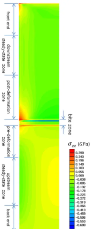
압연이 진행되는 동안 판을 3가지 다른 영역, 소 성 변형 전 영역(pre-deformation zone), 바이트 영역 (bite zone), 소성 변형 후 영역(post-deformation zone) 으로 나눌 수 있다. 소성 변형 전 영역에 앞서 상부 정상상태 영역이 있고 소성 변형 후 영역 뒤에 하 부 정상상태 영역이 있다. 판을 라그랑지안 증분 수 식 (lagrangian incremental formulation)을 기초로 자체적 으로 개발한 코드를 이용하여 정확히 해석하면 이 경계를 정확하게 관찰 할 수 있다 . 이때 롤은 강체 (rigid)로 가정한다. 각각의 경계에 대한 그림이 Fig.
5에 있다. 이 상태에 도달하기 까지는 1,000~3,000
단계(step)의 계산이 필요하며 각각의 단계 마다 응
력과 변형률을 업데이트 한다 . 소성 변형 전 영역은
Fig. 5 Classification of the deformation zones appearing in rolling. The deformation zones are predicted from FE simulation of elastic-plastic deformation of the strip
Fig. 6 Residual stress profiles that are assumed to be present at the upstream steady-state zone
대략 판 폭의 1/2 정도의 길이만큼 존재 하며 소성 변형 후 영역은 판 폭의 3/4 길이만큼 존재함을 알 수 있다.
또한 상부 정상상태 영역에서의 응력 분포가 압 연에 미치는 영향을 알아 보기 위해 각기 다른 응 력 분포를 가정하였다 (Fig. 6). 각기 다른 응력은 소
Fig. 7 Evolution of the longitudinal stress distributions in the pre-deformation zone
Fig. 8 The effect of the residual stress profile in the upstream steady-state zone on the roll force profile
Fig. 9 The effect of the residual stress profile in the upstream steady-state zone on the front and back tension profile
Fig.10 Flow chart for the coupled analysis of the deformation of work roll, backup roll, and strip, a four-high mill is considered
성 변형 전 구간에서 변하게 되며 명확하게 달랐던 응력 분포가 바이트 영역 입측에서는 완벽하게 같 아진다 (Fig. 7). 또한, 응력 분포는 바이트 영역의 소 성변형에는 영향을 미치지 않으며 이것은 압하력, 전방 장력 , 후방 장력을 통해 검증 될 수 있다(Fig. 8, Fig. 9).
4. 탄성 롤, 탄소성 판 연계 해석 방법
탄성 롤 변형과 탄소성 판 변형 연계 시뮬레이션 의 방법은 다음과 같다 .
단계1. 판의 탄소성 변형을 해석한다. 이때 시뮬 레이션은 압하력이 정상상태에 이를 때까지 수행하 며 워크롤은 판에 대하여 유형1 객체로 간주한다.
단계 2. 롤의 탄성 변형을 해석한다. 이때 워크롤 은 첫번째 순서(first rank) 객체가 된다.
단계 3. 현재의 워크롤 형상을 업데이트 한다.
단계4. 단계1, 2, 3을 수렴할 때까지 반복한다.
전반적인 해석 순서를 Fig. 10에 도식화 하였다.
Fig.11 Work roll and strip meshes used for 2-D coupled analysis
Table 1 Process conditions for 2-D coupled analysis of elastic deformation for the work roll and elastic deformation of the strip
case A B C
Diameter, WR [mm] 487.03 503.06 445.09 Entry thickness[mm] 1.158 3.482 1.927
Exit thickness [mm] 1.005 2.875 1.638
Reduction [%] 13 17 15
Young’s modulus,
WR & strip [GPa] 205 205 205
Flow stress [GPa] 0.4 0.4 0.4
Coefficient of friction 0.1 0.1 0.1
5. 적용 3. 2차원 탄성 롤, 탄소성 판 연계 해석
기초 압연 이론에서 아직 검증되지 않은 이론 중 히치콕 수식(Hitchcock’s formula)[4]이 있다. 이는 2차 원 압연에서 바이트 영역의 길이를 예측하는 수식 으로 워크롤의 반지름과 물성치(mechanical properties), 압하력과 관련 있다. 수식의 타당성 확인을 위해 2 차원 탄성롤과 탄소성 판 연계 시뮬레이션을 진행 하였다. 시뮬레이션에 사용한 격자는 Fig. 11과 같다.
시뮬레이션을 진행한 공정 조건은 실제 냉연 공
정에서 선택하였으며 Table 1과 같다. 4번 혹은 5번의
반복(iteration)을 통해 결과를 얻었으며 Fig. 12 에서
보듯이 변형된 롤의 호(arc) 길이가 평탄화(flattening)
(LH – LF )/ LB [%] 7.6 2.2 3.1 roll force, FEM [kN/mm] 4.45 7.55 5.22
Fig.12 Deformation of the roll arc at the bite zone during rolling Case A
되었음을 명백히 알 수 있다 . 시뮬레이션 결과를 정 리한 Table 2를 보면 히치콕 수식이 바이트 영역의 길이가 짧을수록 큰 오차를 가지는 것을 알 수 있 으며 이는 아주 짧은 영역에서 압하 되는 조질 압 연 (skin-pass) 공정 에서 히치콕 수식의 예측 정확도 가 떨어짐을 의미한다 .
6. 적용 4. 3차원 탄성 롤, 탄소성 판 연계 해석
판의 프로파일은 변형된 워크롤의 하부 프로파일 에 영향을 받으며 롤의 변형은 판에서 롤로 전달되 는 압하력 프로파일에 영향을 받는다 . 그러므로 우 리는 다중 접촉 물체 전체에 대한 유한요소 해석이 필요하며 4장에서 설명한 방법을 접촉(contact) 영역
Shaft length [mm] 245 245
Shaft diameter [mm] 130 320
Bender force [tonf] 0.5 -
Young’s modulus, [GPa] 206 206
Poisson’s ratio 0.3 0.3
Strip - Parameters Values
Entry thickness [mm] 2
Exit thickness [mm] 1.4
Initial width [mm] 400
Coefficient of friction 0.03 Front tension [kgf/mm2] 10 Back tension [kgf/mm2] 5
Rolling speed [mpm] 10
Poisson’s ratio 0.3
Flow stress, s [GPa]
s = 0.657 0.003 ( + e )0.214
Fig.13 Mesh for WR, BUR and the strip adopted for 3-D coupled FE simulation of elastic-plastic deformation of the strip and elastic deformation or rolls in a four-high mill
Fig.14 Variation of the deformed roll profile at the bottom of the work roll during iteration, the profile is multiplied by 2 in order to predict the strip profile[5]
에 그대로 적용시키도록 한다 . 4단 압연기에서 워크 롤은 판의 유형1 물체로 간주 되며 판은 워크롤의 유형 2 물체로 간주 된다. 이 시뮬레이션의 공정 조 건은 Table 3과 같다.
Table 3의 공정 조건은 시험 압연기와 동일한 공정 조건이며 이 시물레이션에 사용된 격자는 Fig. 13과 같다 .
시뮬레이션 결과는 탄성 롤과 탄소성 판의 6회 반복 계산을 통해 수렴하였으며 유한요소법을 활용 해 구한 판의 프로파일과 실측치가 매우 잘 맞고 있음을 Fig. 14로부터 알 수 있다.
시뮬레이션 횟수를 반복해 감에 따라 워크롤 하 부의 프로파일이 매우 민감하게 변하고 있음을 알 수 있으며 이는 합리적인(reasonable) 결과를 얻기 위 해서는 워크롤의 형상을 업데이트하는 과정을 매우 신중하게 진행 해야 함을 의미한다.
7. 결 론
본 연구에서 탄성 롤과 탄소성 판 변형에 대한 세 부적인 측면을 유한요소법으로 예측할 수 있음이 증명 되었다.
제안된 유한요소법은 공장 현장에서의 문제 해결 , 압연기 설계 및 공정 제어 등의 다양한 압연 분야 에 적용시킬 수 있다 . 또한 이 접근법은 정밀한 유 한요소법이 온라인 수식 모델 개발에 사용 될 수 있음을 보여 준다 .
(1) Part I에서 제시한 유한요소의 수식화 계산 과 정 등 새로운 접근법을 다양한 시뮬레이션을 통해 그 타당함을 증명하였다.
(2) 새로운 접근법에 의한 유한요소법은 유한요소 법 해석 결과를 기반으로 만들어지는 수식 모델의 정확도 향상과 열간 , 냉간 압연 공정 변형 해석 등 다양한 방면으로 활용 될 것이다.
후 기
이 논문은 2012년도 정부(미래창조과학부)의 재원 으로 한국연구재단의 지원을 받아 수행된 연구임 (No. 2012R1A5A1048294)
REFERENCES