13-4 / S.-H. Cheong
• IMID 2009 DIGEST Abstract
We proposed a transflective liquid crystal display (LCD) with high aperture ratio using an electrophoretic particle layer (EPL). The transflective LCD consisted of the stacked LC layer and EPL which was acted as a switchable mirror under in-plane electrode structure. Without separation of reflective part and transmissive part in one pixel, a mode-selectable display device can be obtained.
1. Introduction
Transflective liquid crystal display (LCD) is one of the most attractive devices for mobile applications due to the advantage of their high performance under indoor and outdoor environments [1]. Under a bright ambient, the transflective LCD was operated with reflective mode where any light-source is unnecessary. Therefore, the readability in the bright ambient as well as the power saving were achieved in the transflective LCD. The conventional transflective LCD consists of two sub-pixels of the transmissive and reflective regions. In order to compensate the optical path difference between two sub-pixels, the variety of the LC structures with the different cell gaps in a single LC mode [1-3] or the different modes in a single cell gap [4,5] were reported. However, these approaches involved the complicated processes and/or the degradation of the display performances. In addition, because the only one sub-pixel works in each transmissive mode and reflective mode, an aperture ratio of the pixel is seriously reduced.
In this work, we propose a transflective LCDs with high aperture ratio using an electrophoretic particle layer (EPL). The LC layer as the switching device is stacked on the top of the EPL which acts as a switchable mirror under in-plane electrode. In this transflective LCD, we could use the whole pixel in both transmissive and reflective modes. Therefore, the aperture ratio of the display increases and the brightness is improved.
2. Cell structure and Operation
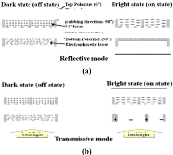
Figure 1 shows the schematic diagrams of a transflective LCD consisting of two crossed polarizers, a LC layer, and an EPL. We fabricated the single substrate LC layer with a maximum λ/2 of the retardation controlled by in-plane electrodes between a top polarizer (0°) and a bottom polarizer (90°). The EPL injected with electrophoretic particles under in-plane electrodes was laminated on the LC layer.
Figure 2 shows the operation principles of the transmissive and reflective parts in our device. When a voltage is applied, in the reflective mode, the linearly polarized ambient light from the top polarizer keeps its polarization after passing through the homogeneous LC cell and is blocked by the bottom polarizer which is along the 90° direction. In the transmissive mode, the transmissive light passing
Transflective Liquid Crystal Display with High Aperture Ratio using Electrophoresis Particles
Seung-Hwan Cheong
1, Kwang-Soo Bae
2, Chang-Jae Yu
1,2, and Jae-Hoon
Kim
1,2*1Dept. of Electronics and Computer Engineering, Hanyang University, Seoul, Korea 2Dept. of Information Display Engineering, Hanyang University, Seoul, Korea
Tel: 82-2-2220-0343, E-mail: [email protected]
Keywords: Liquid Crystal Technology, Flexible and Future Displays, Electronic Paper
(a)
(b)
Figure 1. The schematic diagram of the driving characteristic of our proposed transflective LCD with an electrophoretic particle layer: (a) reflective mode and (b) transmissive mode.
13-4 / S.-H. Cheong
IMID 2009 DIGEST •
through the bottom polarizer from the backlight maintains its polarization state throughout the LC layer and is blocked by the crossed top polarizer.
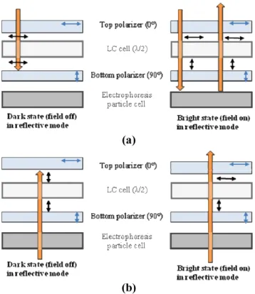
When the voltage exceeds a threshold voltage, the LC directors are reoriented by the electric fields. The deformation of the LC layer results in a retardation and the LC layer acts like a λ/2 plate. In the reflective mode, the linearly polarized light (0˚) of the incoming ambient light from the top polarizer rotates by 90˚ after passing through the LC layer.Then, it is reflected to the LC layer by the EPL where the minus charged electrophoretic particles are uniformly dispersed on the top anode by applying vertical DC voltage. The reflected light propagates along the λ/2 LC layer again and rotates by 90°. Consequently, the 0° polarized light exits the top polarizer. In the transmissive mode, the EPL acts a transparent dummy layer through applying the in-plane field and aggregating the electrophoretic particles onto the in-plane electrodes which is blocked by a black matrix. In this circumstance, the incident light, which is linearly polarized by 90°, is rotated 90° by the LC cell and passes the crossed top polarizer.
3. Cell preparation for Experiment
The LC cell was fabricated with a single substrate by in-plane switching electrodes to reduce the thickness of the
device. The width of each stripe electrodes is 10 μm and the
distance between electrodes is 30 μm. The LC molecules
were aligned at 45° direction from the stripe electrodes. The electrophoretic particle cell for switching the display mode has patterned four-terminal electrodes for good performances in reflective and transmissive mode: two-terminals for an in-plane filed in the transmissive mode and two-terminals for a vertical field in the reflective mode. The electrophoretic particles are titanium dioxide (TiO2) with a
50 nm in diameter and are dispersed with 7% in solvent for their high reflectivity and pure white color [9]. The cell gap was maintained about 20 μm by using spacers to inject
electrophoretic particles easily.
4. Results and Discussion
Figure 3 show the microscopic texture of migrated electrophoretic particles in the reflective and transmissive modes. Fig. 3(a) shows electrophoretic particles migrated on the top anode electrode by applying vertical DC voltage (30 V) between the substrates. In the reflective mode, this EPL acts as a reflector for reflection of the incident light. Fig. 3(b) shows electrophoretic particles migrated toward the anode electrode by an in-plane field. In the transmissive mode, the EPL is transparent except for the anode regions and the incident light from the backlight passes through the EPL.
Figure 4 shows the electro-optic (EO) effects by the in-plane switching (IPS) electrodes in the LC layer. In the absence of an electric field, the LC orientation was parallel or orthogonal to the transmission axes of the polarizers. In such circumstance, the dark state is obtained because the LCs are aligned homogeneously along the rubbing direction coinciding with the transmission direction of the polarizers in both reflective and transmissive modes. When the voltage of 40 V is applied into LC layer, the LC molecules are rotated by 45° with respect to transmissive axis of two polarizers by the in-plane switching electrodes on the substrate of the LC cell. As a result, the LC layer produces a retardation of λ/2 and rotates a polarization
state of the incident light by 90°.
(a) (b) Figure 3. The microscopic textures of migrated
electrophoresis particles in E-particles cell (a) on the top anode electrode and (b) toward the anode electrode by in-plane field.
(a)
(b)
Figure 2. The schematic diagram of the polarization paths of our proposed transflective LCD using an electrophoresis particle cell: (a) in reflective mode (b) in transmissive mode.
13-4 / S.-H. Cheong
• IMID 2009 DIGEST
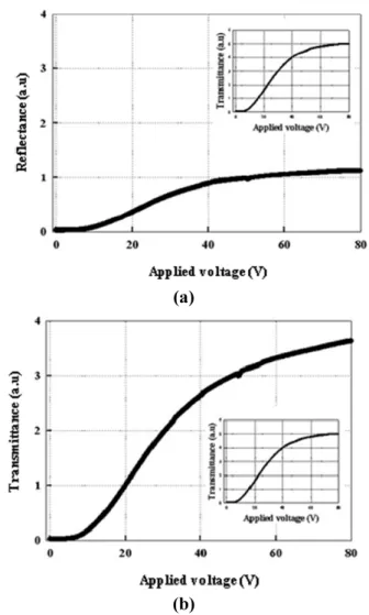
We obtained the reflectance and the transmittance from the measured V-T curves of our proposed transflective LCD. In the reflective mode, the reflectance by electrophoretic particles is about 25% and the contrast ratio is over the contrast ratio limitation of 10:1 as shown in Fig. 5(a). We could also obtain the transmittance which was decreased only about 25% by separated electrophoretic particles on the cathode electrodes in the transmissive mode. The insets in Fig. 5 show the transmittance of the LC layer under crossed polarizers. Contrast ratio of our cell is measured about 110:1. In both modes, the small value of the contrast ratio and rather high voltage could be improved by optimizing the design parameters such as an in-plane switching electrode, microstructures, and an appropriate black matrix.
5. Summary
We proposed the transflective LCD with high aperture ratio under a single mode and single cell gap. The high aperture transflective LCD consisted of the LC layer for an optical switcher modulating the optical transmittance or reflectance and the EPL for a switchable mirror switching the display modes between the transmissive and reflective modes. In this structure, we could use the whole pixel in both transmissive and reflective modes without dividing transmissive part and reflective part in a single pixel. Therefore, the aperture ratio of the display increases and the brightness is improved. It should be expected that the proposed mode could be applied to the high brightness transflective LCDs.
6. Acknowledgements
This research was supported by a grant (F0004052-2008-31) from Information Display R&D Center, one of the 21st Century Frontier R&D Program by the Ministry
of Knowledge Economy of Korean government.
7. References
[1] K. Fujimori, Y. Narutaki, Y. Itoh, N. Kimura, S. Mizushima, Y. Ishii, and M. Hijikigawa, Tech. Digest of SID, 1382 (2002). [2] S. H. Lee, K.-H. Park, J. S. Gwag, T.-H. Yoon, and J. C. Kim, Jpn. J.
Appl. Phys. 42, 5127 (2003).
[3] X. Zhu, Z. Ge, T. X. Wu, and S.-T. Wu, J. Display Technology 1, 15
(2005).
[4] C.-J. Yu, D.-W. Kim, S.-D. Lee, Appl. Phys. Lett. 85, 5146 (2004).
[5] Y. Y. Fan, et. al., Tech. Digest of SID, 647 (2004).
[6] Z. Ge, T. X. Wu, and S.-T. WU, Appl. Phys. Lett. 92, 051109 (2008)
[7] (1997). J.-C. Yoo, K.-W. Lin, and H.-P. D. Shieh, Proc. 4th Asian Symp., 7 [8] R. Lu, Z. Ge, Q. Hong, and S.-T. Wu, J. Display Technology 3, 15
(2007).
[9] R. C. Liang, J. Hou, H. Zang, J. Chung, S. Tseng, Journal of SID 11,
621 (2003).
(a)
(b)
Figure 5. Measured V-T curves of our proposed transflective LCD using an electrophoresis particle cell: (a) reflective mode (b) transmissive mode. (a)
(b)
Figure 4. The microscopic textures at applied voltages of 0, 80V in LC cell: (a) Reflective mode (b) Transmissive mode.