P1-30 / Y. W. Kim
• IMID 2009 DIGEST
Abstract
We demonstrated a liquid crystal display (LCD) mode with a single polarizer based on the array of a switchable microlens consisting of a circular stop mask and its complementary open mask. The focused beam passed through the open mask and thus the bright state was obtained, while the defocused beam was blocked by the stop mask and the complementary open mask. It is expected that our single-polarizer LCD mode is applicable to low cost displays.
1. Introduction
The liquid crystal display (LCD) is most widely used for computer monitors, televisions, digital cameras, cellular phones, and other consumer electronic devices due to the good image quality, low power consumption, and the large visual area. In general, the various optical components such as polarizers and
optical compensating films are mandatory for the LCD with good device performances. However, these mandatory components give rise to the limitation of the cost reduction in the LCDs.
In this work, we demonstrated a novel LCD mode with a single polarizer based on switchable microlens arrays [1-5] with beam-blocking masks. In our single-polarizer LCD mode, a circular stop mask and its complementary open mask, which coincide with the optical axis of a microlens, were successively placed in front of each microlens to control the electro-optic (EO) transmittance (see Fig. 1). From eliminating one polarizer, it should be expected that the single-polarizer LCD mode is applicable to low cost LCDs.
2. Operating Principle
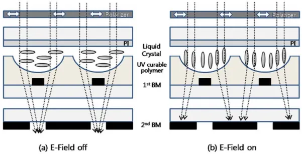
Figure 1 shows the operating principle of the
single-Liquid Crystal Display Mode with a Single Polarizer based
on Switchable Microlens Arrays
Young Wook Kim
1, Jin Seog Gwag
2, Se Hyun Lee
1, Jiwon Jeong
1,
Jae-Hoon Kim
1, and Change-Jae Yu
1*1
Department of Electronics and Communications Engineering, Hanyang University, Seoul 133-791, Korea
Tel.: 82-2-2220-2314, E-mail: [email protected] 2
Department. of Physics, Yeungnam University, Gyeongsan 712-749, Korea
Keywords: liquid crystal display, single polarizer, LC lens
P1-30 / Y. W. Kim
IMID 2009 DIGEST • polarizer LCD mode with the switchable microlens
array. The device configuration consists of a polarizer, surface relief structure on the circular stop mask (first BM), the complementary open mask (second BM), and the LC layer as shown in Fig. 1. In the absence of an applied voltage, the incident beam is focused by the microlens with the planar aligned LCs due to the larger effective refractive index of the LC layer than that of the UV curable polymer. The focused beam passes through the open-hole in the complementary open mask and thus the bright state was obtained even though the focused beam was partially blocked by the circular stop mask as shown in Fig. 1(a).
When the voltage is applied, the LC molecules with positive dielectric anisotropy are rotated parallel to the field direction, that is, vertical to the substrates. In such circumstance, the effective refractive index of the LC layer is slightly smaller than that of the polymer. Therefore, the incident beam is defocused and thus is completely blocked by the circular stop mask and its complementary open mask since the optical axis of the microlens coincides with both centers of the circular stop mask and the complementary open mask (see Fig. 1(b)).
3. Experimental
For fabricating the LC microlens array, we used a self-masking method where the circular stop mask acts as an amplitude mask for forming a lens surface as well as a beam blocking mask. First, we were patterned the circular stop masks (first BMs) with aluminum (Al) using a lift-off method in a conventional photolithography. The diameter and pitch of the circular stop masks are 50 μm and 200 μm, respectively. Next, the lens surface on the circular stop mask was fabricated with the spin-coated the UV curable polymer (NOA60, Norland) on the circular stop mask. The polymer-coated substrate was
irradiated by UV light (λ = 365 nm) from the opposite side of the coated surface. In such circumstance, the circular stop masks blocked the UV light reaching the UV polymer. The spatial modulation of the UV intensity produced the modulation of the monomer density and thus the UV curable monomers are diffused from the blocked regions to the unblocked regions to maintain relative density of monomers. For a complete polymerization, the substrate was irradiated by UV light for some minutes. As a result, lens surfaces exactly matched the circular stop masks. The measured depth and diameter of each microlens were 10 μm and 200 μm, respectively. Fitting the spherical model, the curvature (R) of the single microlens was about 340 μm, which was used to determine the position of the complementary open mask.
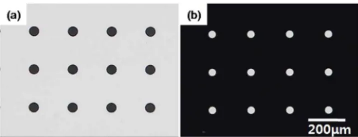
For the complementary open masks (second BMs), we adopt the same process of the circular stop mask. The diameter and pitch of the open mask are 40 μm and 200 μm, respectively. Figure 2 shows the circular stop mask and the complementary open mask made by lift-off method.
The nematic LC (Δn = 0.2361 at 589nm, Δε = 9.8) from Merck was used. For the planar alignment of the LC, RN1199 (Nissan chemical, Japan) is spin-coated on the surface relief structure and upper ITO glass. After rubbing the substrates, two substrates were assembled with anti-parallel direction. Cell thickness was maintained with glass spacers of 3μm. The EO transmittance was measured using He-Ne laser (632.8nm).
4. Results and discussion
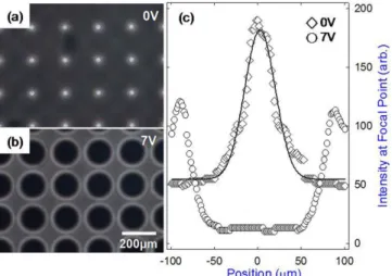
Figure 3 shows the polarizing optical microscopic (POM) images of the focused beam and defocused beam at the focal plane (~2.5mm) without adopting the open mask. In the single-polarizer LCD, the second BM showed by Fig. 2(b) is placed in the focal plane of the microlens arrays. The open-holes of the second BMs coincide with bright spots in Fig. 3(a) and the dark circles in Fig. 3(b). The spatial intensities of the focused and the defocused beams are shown in Fig. 3(c). At 7 V, dark flat region governs the open-hole diameter in the second BMs.
The measured EO transmittance and the charge coupled device captured images of the single-polarizer LC cell at the focal plane were shown in Fig. 4. At zero voltage (first inset), the linearly polarized light parallel to the LC alignment is focused and passes the Figure 2. Black matrices fabricated with Al by
lift-off method: the circular stop masks and (b) the complementary open masks.
P1-30 / Y. W. Kim
• IMID 2009 DIGEST
open-hole mask. With increasing the applied voltage, the LC molecules are gradually tilted out of the substrate and thus the effective refractive index of the LC layer is accordingly decreased. In this situation, the difference of the refractive indices between the LC and the polymer is reduced and the focal length gradually increases, and thus the incident light is diverged. The diverged light partially passes through the open-hole mask and thus the gray levels were achieved depending on the applied voltage (second inset). At high voltage above 5 V, the LC molecules with positive dielectric anisotropy are reoriented vertically. The effective refractive index of the LC layer becomes to be the ordinary refractive index of the LC which is smaller than the refractive index of the UV polymer. Therefore, the LC microlens acts as concave lens and diverges the incident light which is blocked by the masks (third inset). The measured contrast ratio is about 130:1.
5. Summary
We demonstrated the novel LCD mode removing one polarizer through the switchable microlens arrays. In the configuration of the switchable microlens arrays and two complementary black masks, the focused beam and the defocused beam show the on state and the off state, respectively. Using the
single-polarizer LCD mode proposed here, it is expected to reduce the cost of production in the LCDs through removing one polarizer of the mandatory component.
Acknowledgement
This research was supported by a grant (F0004121-2009-32) from Information Display R&D Center, one of the Knowledge Economy Frontier R&D Program funded by the Ministry of Knowledge Economy of Korean government.
6. References
[1] Y. Choi, H.–R. Kim, K.–H. Lee, Y. –M. Lee, and J.–H. Kim, Appl. Phys. Lett. 91, 221113 (2007).
[2] J.–H. Kim and S. Kumar, J. Lightw. Tech. 23, 628 (2005).
[3] M. Ye, Y. Yokoyama, and S. Sato, Appl. Phys. Lett. 89, 141112 (2006).
[4] D.-W. Kim, C.-J. Yu, H.-R. Kim, S.-J. Kim, and S.-D. Lee, Appl. Phys. Lett. 88, 203505 (2006).
[5] Y. Choi, J.-H. Park, J.-H. Kim, and S.-D. Lee, Opt. Mater. 21, 643 (2002).
[6] P. Ruffieux, T. Scharf, and H. P. Herzig, Opt. Exp. 16, 2023 (2008).
Figure 3. (a) The focused beam (on state) at 0 V and (b) the defocused beam (off state) at 7 V on a focal plane. (c) The beam profiles of the on/off states.
Figure 4. The measured EO curve of a single-polarizer LC cell and corresponding textures.