Integrity of a Fuel Channel during a SSE Horizontal Event
J.S.YIM, J.Y.Jeong, B.H.Lee, D.S.Sohn Future Fuel Development Div.
Korea Atomic Energy Research Institute, Yusong PO box 150, Daejon, KOREA [email protected] 1. Introduction
Fuel Channels(FC) should maintain its integrity during an operation in a reactor core in the design base accidents such as a safe shutdown earthquake (SSE). In order to show its integrity during a SSE horizontal motion, a fuel channel was modeled as a spring-mass-beam with a gap element of the ANSYS[1] code. The displacement, stress and moments at each node and element of the model were calculated using the displacement input of the upper core support plate(UCSP), the mid core support plate(MCSP) and the lower core support plate(LCSP). Since there exists a gap between the center of the FC and the mid core support plate(MCSP), the FC horizontal motion would be restricted by the MCSP. If a gap closure occurs, the dynamic impact of the FC will produce a severe stress at this position.
The displacement, stress and moment of each node and element were examined whether the FC contacted with the mid core support plate or not. The nodal maximum stresses of the elements were compared with the design stress limit.
2. Methods and Results
In this section, some of the model and the model input are described.
2.1 Calculation Model
In order to obtain the dynamic responses of a fuel channel, the FC can be modeled as a Spring-mass-Beam model as in Figure 1. The gap between the FC and the mid core support plate was modeled using the COMBIN40 element of ANSYS. The stiffness of the gap element at the MCSP was obtained by the thickness, contact area and young’s Modulus of the MCSP.
The FC was divided into several sections where they had different section properties, i.e. sectional area, material properties and second area moments etc. The model had 84 nodes in the axial direction. The gap between the lower and the upper CEDM guide tube support plates was considered to be large enough not to contact with the FC, thus they were excluded in the modeling.
2.2 Displacement Input
The excitation input of the FC was the displacement history[2] of the UCSP and LCSP as in Figure 2 from
1 3 5 7 25 29 32 37 72 78 84 UCSP FC Flange Mass21 Combin40 Beam3 Barrel Node LCSP 82 76 30 23 36 33 39 74 ICSP 85 86 87 88 89 8 31 38 185 186 187 188 189
Figure 1 FC Horizontal Model
the results of a core structure analysis (performed from NSSS). The MCSP displacement time history was interpolated from the displacement of the UCSP and LCSP. The maximum displacement of the input was about 1 mm in the horizontal direction as shown in Figure 2 and 3
Figure 2 Displacement input at the UCSP
Figure 3 Displacement input at the LCSP Transactions of the Korean Nuclear Society Autumn Meeting
2.3 Calculation Results
The
α
,
β
damping values calculated from the first and 5th natural frequencies of the FC using a criticaldamping ratio of 1%(conservatively used 1 % instead of 2%[3]) were 2.1094 and 9.88764E-06, respectively.
ANSYS transient analysis was used for the calculation. Direct integration of the displacement inputs was used with a auto time step option.
The maximum displacement position to be expected was at the center of the fuel location or the center of the FC. Figure 4 and Figure 5 show the horizontal displacement of the two positions of the FC. It showed that the maximum displacement of the FC at the gap position(nearly center of the FC) was 0.079 mm which did not exceed the amount of the gap size 0.3 mm. Thus FC would not contact with the MCSP during a SSE.
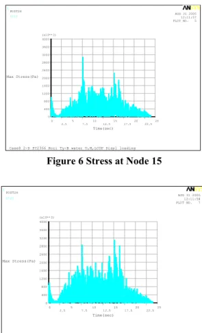
Figure 6 and Figure 7 show the maximum stress (axial membrane plus bending) at the center of the fuel location and the FC. It shows that the maximum stress at the fuel location and the center of the FC were 3 MPa(3 N/mm2), far below the design stress
limit(205N/mm2 for Zr material and 349.2 N/mm2 for
stainless steel) which means the FC will maintain its integrity during a SSE.
1 -.8 -.6 -.4 -.2 0 .2 .4 .6 .8 1 1.2 (x10**-4) Displacement(m) 0 2.5 5 7.5 10 12.515 17.520 22.525 Time(sec)
Case8 2-D FC2366 Hori Ty-B water U,M,LCSP Displ loading
AUG 31 2005 12:11:54 PLOT NO. 8 POST26
Ux16
Figure 4 Displacement at node 16
1 -.8 -.6 -.4 -.2 0 .2 .4 .6 .8 1 1.2 (x10**-4) Displacement(m) 0 2.5 5 7.5 10 12.515 17.520 22.525 Time(sec)
Case8 2-D FC2366 Hori Ty-B water U,M,LCSP Displ loading
AUG 31 2005 12:11:54 PLOT NO. 13 POST26
Ux27
Figure 5 Displacement at node 27
1 0 400 800 1200 1600 2000 2400 2800 3200 3600 4000 (x10**3) Max Stress(Pa) 0 2.5 5 7.5 10 12.515 17.520 22.525 Time(sec)
Case8 2-D FC2366 Hori Ty-B water U,M,LCSP Displ loading
AUG 31 2005 12:11:57 PLOT NO. 5 POST26
St15
Figure 6 Stress at Node 15
1 0 400 800 1200 1600 2000 2400 2800 3200 3600 4000 (x10**3) Max Stress(Pa) 0 2.5 5 7.5 10 12.515 17.520 22.525 Time(sec)
Case8 2-D FC2366 Hori Ty-B water U,M,LCSP Displ loading
AUG 31 2005 12:11:58 PLOT NO. 7 POST26
St21
Figure 7 Stress at Node 21 3. Conclusion
A fuel channel was modeled as a spring-mass-beam with the CONBIN40 element of ANSYS to calculate the displacement, stress and moment at each node and element. Calculation results using the FE Model showed that the maximum displacements of the FC were small enough not to contact with the gap of the MCSP. The maximum stress occurred at the center of the FC and it was far below the stress limit, thus the FC can maintain its integrity during a SSE without any impact to the MCSP.
Acknowledgements
The authors would like to express their appreciation to the MOST for the support of this work through the mid-
and long-term nuclear R&D Project. REFERENCES
[1] SWANSON analysis Inc., ANSYS ver.9.0, 2005.
[2] Regulation guide 1.61, Damping values for seismic design of nuclear power plants