Ⅰ. 서 론
두개안면부위의 분석을 위한 다양한 방법들이 제시되어 왔으며, 이 중 두부규격방사선 촬영은 Broadbent에 의해 처음 소개되었고
1), 전통적으로 두개안면골격의 형태와 성장 양상의 연구에 이용되었다. 이는 두개안면골격의 형태와 성 장 연구의 기준으로 제시되어 이에 근거한 방대한 표준적인 측정치의 수집은 임상가들에게 환자의 개별적 골격양상을 분석, 예측할 수 있도록 하였다. 하지만, 두부규격방사선 촬 영에 기초한 방법들은 내재적, 외재적인 오류로 인한 측정 치 오차 발생의 근원이 되기 쉽고 방법론 자체로서 상의 확 대와 왜곡 때문에 부정확함이 생긴다. 또한 두부규격방사선
촬영을 통한 두개안면부위 계측은 정확하게 보이는 해부학 적 계측점들의 수가 제한적이고, 이러한 계측점들 조차도 방사선사진상 위치가 서로 중첩되는 해부학적 특징으로 인 해 문제점을 내포하고 있다
2,3).
컴퓨터 단층촬영은 현재 진단, 외과적 시술의 계획과 두개 안면 기형의 추적, 관찰에 유용한 양식으로 평가되고 있다.
두부규격방사선 촬영에서 나타나는 상기한 제한점이 많지 않으며, 상의 현저한 확대나 왜곡이 없은 상을 얻을 수 있 다. 특히, 해부학적 구조물의 중첩 또는 위치 파악에 오류가 없고 해부학적 계측점의 수가 매우 많은 장점을 지닌다
2-6). 더욱이 삼차원 영상의 제공도 가능하기에 술 전 계획 및 술 후 평가에 매우 유용하다. 본 연구는 이러한 사실에 근거하 정필훈
1∙유충규
2∙이은경
2∙서제덕
1,2∙정일혁
21
서울대학교 치과대학 구강악안면외과학교실,
2서울대학교 보라매병원 치과-구강악안면외과
컴퓨터 단층촬영을 이용한 중안모 계측과 상악골 절단술에의 응용
MIDFACIAL MEASUREMENT USING OCCLUSAL MAXILLARY CT AND SURGICAL IMPLICATIONS OF MAXILLARY OSTEOTOMIES
Pill-Hoon Choung
1, Chung-Kyu Yoo
2, Eun-Kyung Lee
2, Je-Duck Suh
1,2, Il-Hyuk Chung
21
Department of Oral and Maxillofaciacial Surgery, School of Dentistry, Seoul National University,
2
Department of Dentistry-Oral and Maxillofaciacial Surgery, Seoul National University Boramae Hosipital
Various methods have been used in the past to indirectly analyze the craniofacial region. Among these, the lateral and posterior-anterior cephalometircs are used for the evaluation of the dentofacial deformities.
However, cephalometircs create inaccuracies because of the inherent enlargement and distortion of the image. The interpretation of cephalometric films is also problematic: the number of anatomic landmarks that can be identified accurately is limited, and the overlap of structures on a radiograph making locating these landmarks difficult. To overcome these problems, computed tomography(CT) has been recommended as an useful modality in the diagnosis, surgical planning, and follow-up of craniofacial anomalies. There is no significant enlargement or distortion of the image, overlap of structure, or tracing error. And the number of anatomic landmarks is vast. The purpose of this study was to examine the orbit and midfacial region using Occlusal Maxillary CT, consisted of slices parallel to the occlusal plane. Based on these CT scan, we provide the data that could be applied to monitor an individual patient’s skeletal pattern and the guide to the maxillary osteotomy.
Key words : Computed tomography, Occlusal maxillary CT, Maxillary osteotomy
Abstract
여 컴퓨터 단층촬영을 통하여 안면골격의 해부학적 분석을 실시하였으며, 컴퓨터 단층촬영의 영상획득은 교합평면에 평행하게 이루어진 교합-컴퓨터 단층촬영(occlusal CT)을 통하여 이루어졌다. 이러한 촬영방법은 해부학적 구조물들 의 상호 위치관계 분석의 용이성과 임상적 적용의 편이성에 기인한다. 교합-컴퓨터 단층촬영은 두개저에서 상악골부위 까지 관찰하는 교합-상악 컴퓨터 단층촬영(occlusal max- illary CT)과 이부에서 하악골까지 관찰하는 교합-하악 컴 퓨터 단층촬영(occlusal mandibular CT)으로 구성된다.
본 연구는 교합-상악 컴퓨터 단층촬영(occlusal maxillary CT)을 통한 두개저에서 상악골에 이루는 해부학적 구조물 의 관찰을 실시하였고 이에 근거하여 안면 골격의 수술 전 진단과 이에 근거한 상악골 골절단술의 가이드를 제공하기 위한 것이다.
Ⅱ. 환자 및 연구방법
1. 환자 구성
본 연구는 턱교정 수술을 시행하기 위해 서울대학교 치과 병원 구강악안면외과에 내원한 63명의 환자를 대상으로 실 시하였다. 이들 환자군은 중안모 후퇴, 하악골 전돌, 안면비 대칭과 부정교합의 진단하에 Le Fort I, Le Fort II 골절단 술, 구내하악지시상수직 골절단술(Intraoral Vertico Sagittal Ramus Osteotomy, IVSRO), 구내관골상악골절 단술 (Intraoral Zygomaticomaxillary Osteotomy)를 실 시하였다. 총 63명의 환자는 남자 35명, 여자 28명으로 구 성되었으며, 연령은 17세에서 47세의 범위를 나타냈다 (Table 1).
2. 컴퓨터 단층촬영 및 해부학적 구조물의 측정
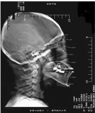
컴퓨터 단층촬영(Occlusal Maxillary CT)은 표준화된 촬영 조건하에서 교합평면에 평행하도록 이루어졌다 (Toothpix I.Q. CT scanner, Pickeer Co. Fig. 1). 모든 단층촬영은 2 mm의 두께로 4 mm 간격으로 시행되었으며
측정은 동일성과 재현성 및 임상적 유의성을 나타내기 위해 동일한 사람에 의해 이루어졌다. 계측점의 측정은 획득한 영상에서 미세점의 보정장치와 1�의 각도기로 얻어졌고, 각 영상에 나타난 참고 범위로 표준화하였다.
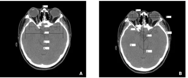
재현성과 명확한 계측점의 선택, 계측의 동일성 및 수월성 을 위해 6개의 단층촬영면이 선택되었다. 각각의 단층촬영 면은 교합평면에 평행하도록 하여 촬영이 이루어졌으며, 상 악골 골절단술과 연관된 해부학적 구조물의 연구에 이용되 었다. 첫 번째 선택된 단층촬영면은 안와 부위로서 안구의 수정체, 사골의 함기동(air cell), 안구의 내측, 외측 수직 근, 비골, 관골의 전방 돌기의 상방부위의 절단면이다(Fig.
2). 전방 안와간거리, 외측 안간거리, 양측두간거리, 내측 안벽길이, 외측 안벽길이, 안구 돌출도, 내측 안벽돌출도, 외측 안벽각이 측정되었다(Table 2). 두 번째 선택된 단층
Fig. 1. Occlusal maxillary CT, all slices are parallel to the occlusal plan.
Table 1. Patients Age and Gender Distribution
Age/Gender Female Male sum
11-20 5 7 12
21-30 20 25 45
31-40 2 3 5
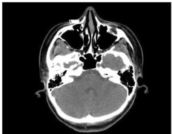
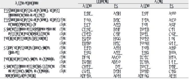
촬영면은 전두비골봉합 부위를 지나는 면으로 이 부분의 피 질골 두께를 측정하였다(Fig. 3). 세 번째 단층촬영면은 안 와하방 부위로서 안와하연을 지나는 면으로 양쪽 비루관 (nasolacrimal duct)의 바깥쪽 피질골의 두께를 측정하였 다(Fig. 4). 네 번째 단층촬영면은 비강부위이며 비와(piri- form rim)와 상악동, 익구개와를 가로지르는 촬영면으로 비와의 전방부에서 양측의 대구개신경관까지의 거리를 측 정하였다(Fig. 5). 다섯 번째는 상악 대구치 치근이 보이지
않는 가운데 상악동부위에서 상악동과 익상판을 지나는 면 으로 익돌상악열(pterygomaxillary fissure)의 깊이와 익 상판의 각도를 측정하였다(Fig. 6). 여섯 번째 단층촬영면 은 구개부위인데 경구개와 상악결절을 지나는 면으로 절치 와에서 상악 결절까지의 거리와 교합평면에 평행한 축에 대 한 상악 결절의 굴곡도를 측정하였다(Fig. 7). 아울러 양측 하악과두간의 각도가 극공(foramen spinosum)이 나타나 는 단층촬영면에서 측정되었다.
Fig. 2. The first slice for the evaluation of the orbit. (A) A: anterior interorbital distance, B: lateral orbital dis- tance, C: intertemporal distance (B) D: medial orbital wall length, E: lateral orbital wall length, F: globe pro- trusion G: medial orbital wall protrusion, H: lateral orbital wall angle.
Table 2. Descriptions of Measurements of the Orbital Region
Measurement Description
Anterior interorbital distance The distance between a point on each lacrimal bone representing the anterior end of the medial orbital wall
Lateral orbital distance The distance between the most anterior tip of each lateral orbital wall Intertemporal distance The distance between the most medial aspect of each temporalis groove Medial orbital-wall length The distance between the lacrimal bone and base of the optic strut Lateral orbital-wall length The distance between the most anterior tip of the lateral orbital wall
and the base of the optic strut
Globe protrusion The perpendicular distance between the anterior tips of the lateral orbital wall and the most anterior aspect of the globe.
Medial orbital-wall protrusion The perpendicular distance between the anterior tips of the lateral orbital walls and the lacrimal bone
Lateral orbital-wall angle The angle formed between a line joining the most anterior and posterior ends of the lateral orbital wall and the sagittal axis.
A B
A
C
B
F
E
H
G
Fig. 3. The second slice for the evaluation of the fron- tonasal suture area. (A: thickness of the outer cortex of the frontonasal suture area)
Fig. 4. The third slice for the evaluation of the infraor- bital region. (A: thickness of the outer cortex of the nasolacrimal duct)
Fig. 5. The fourth slice transected the piriform rim. (A:
distance from the pyriform rim to the greater palatine canal)
Fig. 7. The sixth slice in the palatal portion. (A: distance from the incisive canal to the maxillary tuberosity, B:
Fig. 6. The fifth slice transected maxillary sinus and
pterygoid plate area. (A: angle of the pterygoid plate)
Ⅲ. 연구 성적 및 결과
안와 골격의 계측을 위한 전방 안와간거리, 외측 안간거 리, 측두간거리, 내측 안벽길이, 외측 안벽길이, 안구 돌출 도, 내측 안벽돌출도, 외측 안벽각이 측정되었고 그 평균값 은 Table 3에 기술되어 있다. 중안모 골격 분석을 위한 계 측과 상악골 절단술의 기준을 위한 전두비골봉합 부위의 피 질골 두께, 비루관 외측 피질골의 두께, 비와의 전방부에서 대구개신경관까지의 거리, 익돌상악열의 깊이와 익상판의 각도, 절치와에서 상악 결절까지의 거리와 상악 결절의 굴 곡도와 양측 하악과두간의 각도가 측정되었고 그 평균값은 Table 4에 기술되어 있다.
Ⅳ. 총괄 및 고찰
중안모 개선을 위한 골전단술과 관련하여 안와를 포함한 중안모는 임상적, 해부학적 연구들의 주제가 되어왔다
7,8). 이는 안와 골격 및 중안모 골격의 계측을 통한 표준화된 계 측치의 확립과 아울러 골절단술 시 나타날 수 있는 해부학 적 구조물의 손상을 최소화하기 위함이다. 따라서 본 연구 는 컴퓨터 단층 촬영을 통하여 상악골절단술과 연관된 해부 학적 구조물의 관찰을 실시하였다. 본 연구에서 컴퓨터 단 층 촬영면은 교합평면에 평행하도록 하여 촬영을 실시하였 는데, 이는 중안모 구조물의 해부학적 분석을 위한 단층 촬 영면의 임상적 적용이 용이하도록 하기 위함이다.
Table 3. Measurements of the Orbital Region on the Occlusal Maxillary CT
Measurements Female Male
Mean SD Mean SD
Anterior interorbital distance 16.22 2.75 18.31 3.49
Lateral orbital distance 94.96 3.48 102.04 6.21
Intertemporal distance 84.66 6.08 87.41 5.52
Medial orbital wall length (Lt) 44.52 2.94 45.73 3.28
(Rt) 43.93 2.71 44.42 3.61
Lateral orbital wall length (Lt) 46.82 4.95 49.58 3.86
(Rt) 47.39 4.73 48.57 4.04
Globe protrusion 17.07 2.56 17.43 2.50
Medial orbital wall protrusion 10.73 2.18 10.28 1.97
Lateral orbital wall protrusion (Lt) 45.50 4.30 45.50 2.59
(Rt) 46.45 3.60 44.77 2.60
Table 4. Measurements of the Midfacial Region on the Occlusal Maxillary CT
Measurements Female Male
Mean SD Mean SD
Thickness of the outer cortex of the
frontonasal suture area 5.25 1.28 5.06 1.00
Thickness of the outer cortex of the (Lt) 6.11 2.23 6.41 1.30
nasolacrimal duct (Rt) 5.36 1.54 6.09 1.76
Distance from the piriform rim to (Lt) 35.15 2.86 40.52 3.69
the greater palatine canal (Rt) 34.54 3.26 40.59 3.75
Angle of the pterygoid plate (Lt) 57.40 8.77 60.50 9.19
(Rt) 58.20 8.53 60.18 7.95
Depth of the pterygomaxillary (Lt) 5.64 1.68 6.02 1.80
fissure (Rt) 5.07 1.55 5.87 2.01
Angle of the maxillary tuberosity (Lt) 46.19 11.30 43.43 8.61
(Rt) 47.28 12.90 43.81 9.95
Distance from the incisive canal (Lt) 38.55 4.5 40.35 4.25
to the maxillary tuberosity (Rt) 37.59 4.48 40.84 3.87
Intercondylar angle 146.21 10.8 146.17 15.8
상악골절단술과 관련된 안와 및 비루계의 손상의 위험성 에 대해서 많은 연구가 이루어졌다
7-9). 일반적으로 유루계 (lacrimal drainage system)는 누소관(canaliculi), 누낭 (lacrimal sac), 비루관(nasolacrimal duct)으로 이뤄져 있다. 비루관은 안와 내측의 누낭에서 시작하여 비루소관 (nasolacrimal canal)을 통과하여 하비갑개골의 밑에 있는 코의 하방출구에서 끝난다. 중안모 개선을 위한 상악골 절단술시 비루관의 손상을 초래할 수 있으며 이에 수반되어 일시적 또는 영구적인 유루증(epiphora)을 초래할 수 있
다
10,11). 평균적으로 비강저에서 비루개부(nasolacrimal
meatal portion) 개구부까지의 거리는 11~17 mm이고 이는 전통적인 Le Fort I 골절단술에 의한 상악 이동의 대 부분의 경우에서 안전한 거리이다
7,12). 하지만 안와, 비골, 관골부위까지 골절단선이 포함되는 Le Fort II, III 골절단 술에서는 비루관 개구부 상방에서 이뤄져야 한다
9,13,14). 따라 서 골절단은 비루관의 전방 피질골에 국한되어야 비루개의 손상을 방지할 수 있다. 또한, 구내 Le Fort II, III 골절단 술에서 비골 부위의 사선 골절단(oblique osteotomy)은 하 안와연의 수준에서 수행된다. 이 곳에서 비루관은 외측 피 질골의 후방에 위치하는데, 본 교합-상악 컴퓨터 단층촬영 을 통해 측정한 하안와부위의 비루관 외측 피질골의 두께는 여성의 경우 좌측 6.11 mm(표준편차 2.23), 우측 5.36 mm(표준편차 1.54)이고, 남성에서는 좌측 6.41 mm(표 준편차 1.30), 우측 6.09 mm(표준편차 1.76)의 수치를 보였다. 따라서 비골 부위의 골절단이 비루관의 손상을 방 지하기 위해서는 외측 피질골 후방 5 mm 이상의 연장은 피 해야 한다.
일반적인 Le Fort II, III 골절단술에서 비골-상악 복합체 의 이동을 위해서는 전두비골봉합부위가 분리되어야 하며 그 수직적 높이는 볏돌기(crista galli) 부위에 해당된다. 교 합-상악 컴퓨터 단층촬영을 통한 연구에서 전두비골봉합부 전방부 피질골의 두께는 여성에서 5.25 mm(표준편차 1.28), 남성에서 5.06 mm(표준편차 1.00)이다. 따라서 전두비골 봉합 부위의 골절단은 외측 피질골에서 5 mm 연 장될 수 있다. 또한 술 전 컴퓨터 단층촬영을 통한 사골판 (cribriform plate)의 위치 파악이 중요한데, 이는 전두개 구조물의 하방함입에 따른 사골판의 하방 변위를 초래할 수 있기 때문이다. 이러한 경우 전두비골봉합부 골절단선을 하 방에 위치시켜 두개 구조물의 손상을 최소화하도록 해야 한다.
상악골 절단술의 상악부위의 악안면 기형교정으로서 흔히 행해지는 방법으로 수술 중 계획된 위치로의 원활한 상악골 이동을 위한 익돌상악접합부위 및 구개골의 상악돌기의 분
artery) 손상에 기인하는 출혈이 가장 흔하다. 일반적으로 내측상악동맥은 익구개와로 들어가며 하행구개동맥으로 분 지된다. 하행구개동맥은 구개골의 수직부위에 위치한 대구 개신경관에 놓여 있으며 상악골 수평절단술 도중에 쉽게 손 상을 받을 수 있으며 이로 인한 출혈을 야기 할 수 있다
16,17). 교합-상악 단층 촬영을 통한 본 연구에서 비강 개구부에서 대구개관까지의 거리는 남성의 경우 좌측이 40.52 mm(표 준편차: 3.69), 우측이 40.59 mm(표준편차: 3.75), 여성 의 경우 좌측이 35.15 mm(표준편차: 2.86), 우측이 34.54 mm(표준편차:3.26)의 평균값을 보였다. 따라서 내 측상악동맥의 손상을 피하면서 상악골의 분리를 위한 내측 상악동벽의 골절단선은 비강 개구부 후방으로 남성의 경우 40 mm, 여성의 35 mm 정도 연장할 수 있다. 일반적으로 여성의 경우 내측상악동벽 골절단술 시 비강개구부에서 후 방으로 30 mm, 남성의 경우 35 mm 연장하는 것이 추천 되었다
18). 이는 본 연구에서 측정한 비강 개구부에서 하행구 개동맥까지의 거리 남성에서 38.4 mm, 여성에서 34.6 mm의 측정치와 상응하는 것이다.
상악골절단술 시 익돌상악접합부위의 분리는 매우 중요한 과정이며 이에 대한 임상적, 해부학적 보고가 이루어졌다
19-21). 한국 성인 두개골의 조사에서 익돌상악 봉합의 길이는 각각 좌측 15.7 mm, 우측 15.9 mm의 평균값을 보였으며, 시 상면에 대한 상악결절의 각도는 좌측에서 38.5�, 우측에서 40.3�였다
22). 따라서 상악골 분리 시 익상판의 골절을 막 기 위해서는 골절단기(osteotome)를 협측으로 40�이상의 각도를 유지하면서 골절단을 시행하여야한다. 교합-상악 컴 퓨터 단층 촬영을 통한 상악결절의 각도는 여성의 경우 좌 측 46.19�(표준편차 11.3), 우측 47.28�(표준편차 12.9), 남성의 경우 좌측 43.43�(표준편차 8.61), 우측 43.81�(표 준편차 9.95)였다. 교합-상악 컴퓨터 단층 촬영을 통한 상 악결절의 각도는 이전에 실시한 두개골 연구의 결과와 일치 한다. 또한 골절단기 삽입의 최대 허용 길이는 절치공에서 약 40 mm까지 후방으로 위치시킬 수 있다.
Ⅴ. 결 론
상악골 절단술- Le Fort I, II, III osteotomy-은 중안모
성장 및 발육 이상의 교정을 위한 수술법으로 흔히 행해지
고 있으며 이러한 수술은 안와, 비골, 상악골 및 관골부를
수술 영역에 포함하기에 이 부위 해부학적 구조물의 파악은
술전 계획의 수립과 수술 중 생길 수 있는 주요 구조물의 손
상 방지에 필수적이라 할 수 있다. 본 연구는 교합-상악 컴
퓨터 단층 촬영을 통하여 상악골 절단술과 연관된 해부학적
점을 지닌다. 또한 이러한 촬영을 통한 해부학적 구조물의 분석은 상악골 골절단술에 유요한 정보를 제공하는 것으로 판단된다.
참고문헌