Journal of International Society
for Simulation Surgery
JULY 2014
VOL. 1 NO. 1
The time of rapid development in the field of computers in the 1990s, also marked the beginning of an era of anticipating significant medical surgical advancements for the future, particularly in the field of plastic surgery.
International Society for Simulation Surgery (ISSiS) was founded in 1992 by plastic surgeons, Drs. Toyomi Fujino (Japan) and Jeffrey L. Marsh (USA).
In the beginning, ISSiS was held with the Computer Aided Surgery Society and the Computer Aided Radiology Society, mostly in Europe, America and Japan.
ISSiS has since held biannual congresses in Thailand (5th, 2006), Taiwan (6th, 2008) and Hawaii (7th, 2010).
In 2012, the 8th congress was held in Seoul. ISSiS previously specializing only in plastic surgery, began to expand the field of the society to cover computer, simulation and surgery as a chapter of convergence science. This congress and the expansion were very successful. As a result, scholars at home and abroad saw the potential for development and availability of 3D simulation surgery, and the headquarters was moved to Korea. The Seoul office became responsible for the operation and sustainability of ISSiS.
The 21st century has been called the era of the life sciences.
Aspects of development of science and technology offer us a vision of new medical advances several generations into the future. Advanced engineering, the development of scientifically based emerging technology, breakthroughs in computer technology and the U.S. military state-of-the-art intensive research in the field of simulation surgery have all contributed to this vision. Simulation Surgery, not just as a simple medical field, but a fusion of future medical industries, will revolutionize research, treatment, education, science and technology. The multi-disciplinary ISSiS will continue to push forward in this effort.
The Journal of International Society for Simulation Surgery is published.
We want this journal to continue to develop and expand its content. However, this will not be possible with only the efforts of the president and board members. I would like to ask in earnest for all members to more actively participate and contribute to this effort and for the success of the greater ISSiS.
Thank you very much.
●○●○●○●○●○●○●○●○●○●○●○●○●○●
●○●○●○●○●○●○●
Greeting
Greeting
Yong Oock Kim, President
Professor Plastic & Reconstructive Surgery
ISSN 2383-5389
Volume
1
Number1
July 2014
Korean Board Committee of ISSiS
Editorial Board
President Auditor Secretary
Scientific Committee Chair International Committee Chair Planning Committee Chair Publicity Committee Chair Finance Committee Chair Education Committee Chair Editing Committee Chair
Yong Oock Kim (Plastic & Reconstructive Surgery, Yonsei University Severance Hospital) Sangyoun Lee (Electrical & Electronic Engineering, Yonsei University)
In Sik Yun (Plastic & Reconstructive Surgery, Yonsei University Severance Hospital) Young-Soo Jung (Oral & Maxillofacial Surgery, Yonsei University Severance Hospital) Kang-Min Ahn (Oral & Maxillofacial Surgery, Seoul Asan Medical Center)
Sanghoon Lee (Electrical & Electronic Engineering, Yonsei University) Sung-Hwan Kim (Orthopedic Surgery, Yonsei University Severance Hospital) Jong-Woo Choi (Plastic & Reconstructive Surgery, Seoul Asan Medical Center) Helen Hong (Multimedia Engineering,Seoul Women’s University)
Joonseok Lim (Radiology, Yonsei University)
Editor in Chief Associate Editor
Joonseok Lim (Radiology, Yonsei University Severance Hospital) Song-Ee Baek (Radiology, Yonsei University Severance Hospital)
INSTRUCTIONS FOR AUTHORS
JOURNAL OF INTERNATIONAL SOCIETY FOR SIMULATION SURGERY
(Enacted in May 2014)
1. Manuscripts include original articles, reviews, case reports, special communication (requested by Editorial Board), editor’s com ments, and letters to the editors.
2. Neither manuscripts submitted nor manuscripts substantially similar to the submitted material may be published elsewhere. 3. Manuscripts should be written in Korean or English and must be provided in Microsoft Word (.doc), Hangul (.hwp), or PDF (.pdf) formats.
4. General instructions for manuscript preparation
A. Manuscripts should be double-spaced with 3 cm margins at the left, upper, and bottom of an A4 sheet size (21 × 30 cm). All manuscripts must be numbered consecutively starting from the abstract page.
B. The manuscript should be assembled in the following sequence: title, abstract, introduction, materials and methods, results, discussion, acknowledgments, references, tables, and figure captions.
C. Title page:
In the title page, the titles of manuscripts and the names and affiliations of all authors should be in cluded in both Korean and English. In the case of foreign authors, they may be written in English only.
D. Abstract:
The abstract must be written in English. The abstract should be consisted of the following structure (Purpose-Materials and Methods-Results-Conclusion). 5 MeSH words registered in the MEDLINE/PubMed database should be included at the bot tom of the English abstract for key index.
E. References:
Each author should be listed up to a maximum of 6; if the number of authors exceeds 6, only the first 6 authors should be listed followed by the denotation “et al.”.
• Journal articles
1. Lee SA, Jung HH, Lee SH, Cha SH, Jas BK, Seo BK, et al. Venogram with the tourniquet technique for the evaluation of central vein patency: comparison to conventional CO2 venogram. Korean J Radiol 2011;65:61-68
• Books
2. Kang HS, Resnick D. MRI of the extremities: an anatomic atlas. Philadelphia: Saunders, 1991:62-79 F. Tables should be provided in Arabic numerals and English.
G. Figures
When there are more than 2 figures under the same number, they should be differentiated by a letter after each Arabic number (Example: Fig. 1A, Fig. 1B).
5. Specific types of manuscripts
A. Review: Reviews focus on special topics and are published based upon the requests of the Editorial Board. B. Case reports
1. Structure of case reports: Abstract-Introduction-Case report-Discussion-References
2. Sections such as introduction, materials and methods, and conclusion should not be organized separately in the abstract.
Manuscripts
Contents
Contents
Volume
1
Number1
July 2014
ISSN 2383-5389
7 Measurement of Orbit using Standardized Processing of CT Scan Yong Oock Kim 13 The Manufacture of Custom made 3D Titanium Implant for Skull Reconstruction
Hyung Rok Cho, In Sik Yun, Kyu Won Shim, Tai Suk Roh, Yong Oock Kim 16 Application of 3D Simulation Surgery to Orbital Wall Fracture : A Preliminary Case Study Jong-Woo Choi 19 Three-dimensional Reconstruction of the Knee for Ligament Reconstruction Sung-Hwan Kim, Seung-Joo Ha 23 Application of 3D Simulation Surgery to Orthognathic Aurgery : A Preliminary Case Study Jung-Hwan Lim, Hyun-young Kim, Young-Soo Jung, Hwi-Dong Jung 27 Segmentation and 3D Visualization of Medical Image : An Overview Jiwoo Kang, Doyoung Kim, Sanghoon Lee 32 Maxillary Reconstruction with Free Fibular Flap using 3D RP Model Kang-Min Ahn, Jong-Jin Kim 37 Automatic Liver Segmentation on Abdominal Contrast-enhanced CT Images for the
Pre-surgery Planning of Living Donor Liver Transplantation
Yujin Jang, Helen Hong, Jin Wook Chung 41 Preoperative CT Navigation of Perigastric Vessel Anatomy for Gastrectomy Song-Ee Baek, Woo Jin Hyung, Joon seok Lim 47 Application of Simulation in Healthcare Education Hyun Soo Chung 48 3D Medical Standard : Over the Horizon Young Lae Moon, Dae Ok Kim, Hong Moon Sohn 49 Image-guided Navigation for Non-invasive Functional Neuromodulation Using Focused
Ultrasound Hyungmin Kim
50 Surgical Simulation for Pancreatic Reconstruction following Pancreatectomy Chang Moo Kang 51 Finite Element Modelling of the Knee and Its Application Young-Jin Seo
52 Virtual Reality coming from Medical Images Jinah Park
53 3D Scanning Technology for Digital Dentistry Minho Chang 54 Clinical Validation of CAD/CAM Technology : From Virtual Set Up to Indirect Bonding System Jung Yul Cha 55 Clinical Application Ideas for Minimally Invasive Surgery Kwanggi Kim
ISSN 2383-5389
A
BSTRACT
Journal of International Society for Simulation Surgery 2014;1(1):7-12
서 론
안구는 전체 중 세 부위가 superior, medial, inferior 가 각 각 frontal sinus, ethmoid sinus, maxillary sinus로 둘러 싸여 있다. 그래서 상당한 충격에도 안구가 직접 손상을 입기 전에 안구를 둘러싼 sinus와 골 조직들이 먼저 부서져 많은 충 격을 흡수해 줌으로서 안구를 보호한다. 그 결과 안구 주변의 골 조직이 파괴되는 심각한 손상에서도 안구 자체의 손상은 피 할 수 있어 시력이나 시야의 변화는 없는 경우가 흔히 발생한 다. 그러나 시력이라는 기능적인 면의 손상은 없어도, 안구를 둘러싼 골조직의 위치 변화와, 안구를 둘러싼 연조직의 용적 변 화로 안구의 위치가 바뀌게 되어 미용적인 문제점으로서 내안
O
riginal Article
Measurement of Orbit using Standardized
Processing of CT Scan
Yong Oock Kim, M.D., Ph.D.
Department of Plastic & Reconstructive Surgery, Institute of Human Tissue Restoration, Yonsei University College of Medicine, Seoul, Korea
PurposeZZSurgical correction of various occular problems which do not have visual problem in plastic surgical area is to nor-malize the appearance of the face by restoring the normal position of orbit and eyeball. With development of surgical technique, the orbit can be restored exactly in trauma patient and can be moved totally in hypertelorism, as an example of congenital disease. All these surgeries are based on the hypothesis that the position of oclular glove moves in the plane in a quantitatively predictable reationship to osseous orbit movement. However, no studies have critically evaluated between the change of periorbital soft tissue and the outcome of the surgical correction, because there is no method of objective, quantitave evaluation of the periorbital soft tissue.
MethodZZAuthor suggest the methodology for quantitative assessment of ocular and periocular fat changes using the manipula-tion of digital images of computed tomographic scan.
ResultsZZThe method was allowed to evaluate inter-dacryon distance, inter-centroid distance, movement of the medial orbital wall, movement of the lateral orbital wall, alteration of thickness of the lateral periorbital fat as indicator of movement of the orbit-al worbit-all and orbit in the patient with congenitorbit-al periorbitorbit-al anomorbit-aly and postoperative periorbitorbit-al surgery. The goorbit-al of surgicorbit-al cor-rection of various occular problems which do not have visual problem in plastic surgical area is to normalize the appearance of the face by restoring the normal position of orbit and eyeball. With development of surgical technique, the orbit can be restored exact-ly in trauma patient and can be moved totalexact-ly in hypertelorism, as an example of congenital disease. All these sugeries are based on the hypothesis that the position of oclular glove moves in the plane in a quantitatively predictable relationship to osseous orbit movement. However, no studies have critically evaluated between the change of periorbital soft tissue and the outcome of the sur-gical correction, because there is no method of objective, quantitave evaluation of the periorbital soft tissue. In this report, author suggest the methodology for quantitative assessment of ocular and periocular fat changes using the manipulation of digital images of computed tomographic scan.
ConclusionZZThe method suggested is objective and accurate method in measurement of the orbital contents. It takes time and is not easy to do, however, this kind of measurement for fine structures will be more easily available in near future.
Key WordsZZOrbit ㆍPeriorbital Soft Tissue ㆍQuantitative Measurement ㆍComputed Tomographic (CT) scan.
Received: July 4, 2014 / Revised: July 11, 2014 / Accepted: July 15, 2014 Address for correspondence: Yong Oock Kim, M.D., Ph.D.
Department of Plastic & Reconstructive Surgery, Institute of Human Tissue Restoration, Yonsei University College of Medicine, 50 Yonsei-ro, Seodae-moon-ku, Seoul 120-752, Korea
Journal of International Society for Simulation Surgery█ 2014;1(1):7-12 증, telecanthus 등이 흔히 관찰되어 왔으며, 심한 경우 양안 격리증 소견까지도 나타난다.1 이와같은 안구 위치변화는 현재까지는 외부에서 관찰되는 소 견에 의해 대부분 보고 되고 있으며, 그 원인으로서는 골조직의 위치변화, 안구 주변 연조직의 용적 변화가 주 원인일 것이라는 물리적 상황에 대한 추측으로만 이해되고 있다. 이는 해부학적 구조상 어떤 기준점에 대한 안구의 절대적인 위치나 안구를 둘 러싼 여러 연조직 각각의 용적이나 위치 변화를 측정할 수 있 는, 그리고 서로 다른 측정자들에 의해서 측정이 되어도 그 오 차가 극히 미미할 수 있는 측정 방법이 없었다. 그 결과 이 부위 의 질병이나 손상에 따른 수술적 결과에 대한 보다 정량적인 원 인 분석이나 이에 따른 대처 방법의 개발이 미비했다고 할 수 있다. 이에 본 저자는 안구 주변의 기본적인 연 조직의 위치 변 화를 컴퓨터 단층 촬영의 디지털 이미지 데이타를 이용하여 3 차원적인 안구 구조에 기초를 둔 안구의 연조직 측정 방법을 제 시하고자 한다.
방 법
최근 컴퓨터의 발달로 컴퓨터 단층 촬영의 영상이 디지털 이 미지 데이타로서 사용 됨으로서 컴퓨터에 의힌 의료 영상 시스 템 (Computer assisted medical imaging system)의 도움으 로 삼차원 영상의 구현이나 이 삼차원 영상에서의 위치나 거리, 용적등의 정량적인 측정이 많이 용이해졌다.2 컴퓨터 단층 촬영 의 데이터는 골조직의 영상을 가장 잘 보여주고, 삼차원 영상처 리가 가능한 진단 방법으로 본 연구에서는 이차원 컴퓨터 단층 촬영의 데이타를 사용하였다.1. 컴퓨터 단층 촬영 데이터 처리 (Fig. 1)
1) 컴퓨터 단층 촬영 데이타의 획득 컴퓨터 단층 촬영은 표준 컴퓨터 단층 촬영기를 사용한다. 단층 촬영은 고해상도, contiguous, non-overlapping 2mm trans-verse slice로 촬영한 후 magnetic optical disk에 저장한다.2) 데이타의 전송
Local network communication을 통해 컴퓨터 단층 촬영 기로 부터 computer workstation으로 데이타를 전송하고 보 관한다.
3) 데이타 변환
보관된 digital data는 AnalyzeTM software에서 사용가능
한 image file로 변환한다. 이 과정은 프로그램 내에 내장된 module에 의해 시행되는 것으로 원래 컴퓨터 단층 촬영의 im-age data에는 전혀 손상을 주지 않는 과정이다. 변환된 데이타 는 3차원적인 Volume 이미지로 보여줄 수 있도록 재구성(re-format) reformat 시킨다. 재구성 (re재구성(re-format)된 데이터는 원래 컴퓨터 단층 촬영에서 획득된 많은 수의 2차원적 axial image 데이터가 합쳐져 3차원 영상을 보여주는 파일 형식으로 바뀐다. 4) Registeration of position 서로 다른 환자에서 촬영된 컴퓨터 단층 촬영 상의 두개골의 위치는 서로 다르다. 이렇게 다른 단면의 컴퓨터 단층 촬영의 결 과를 그대로 사용하여 거리나 부피를 측정할 경우 두 결과는 비 교할 수 없는 결과를 보여주게 된다. 따라서 촬영시 정확히 맞추 기 어려운 두개골의 위치를 컴퓨터 상에서 정확히 맞추어 주는 작업이 필요하며, 이러한 위치 조절 (registration of postition) 은 두개골 양측의 Internal auditory meatus와 anterior na-sal spine이 속하는 평면을 수평 평면으로 한 후, 이에 직각으 로 anterior nasal spine과 basion을 지나는 평면을 수직 평면 으로 하여 서로 다른 위치에서 촬영된 3차원 CT 데이터를 동일 한 위치로 재구성 하였다 (Fig. 2).
2. 측정
1) 측정점 선택
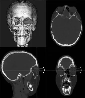
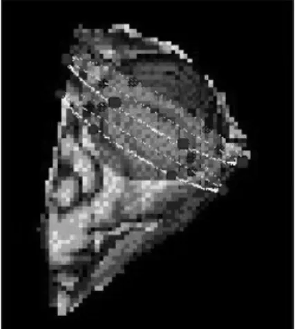
서로 다른 단층 촬영 영상에서 동일한 측정점을 취하기 위한 방법으로 3차원 골조직 영상과 함께 axial, coronal, sagittal 의 2차원 영상도 동시에 영상화하여, 각 측정점들의 3차원 좌표 를 구한다. 안구를 동일한 구획으로 나누는 가상 평면과 선 설정 : 안와 내외벽과 내외측의 지방층과 같은 연조직 두께의 정확하고, 동 일한 측정을 위해 안구의 중심점을 지나는 수평면 (Plane 2)을 설정하고, 이 수평면과 안구의 위쪽 끝 사이를 양분해 주는 수 평면 (plane 1), 그리고 안구의 아래쪽 끝 사이을 양분해 주는 수평면 (plane 3)를 설정하였다. 다시 각각의 수평면에 투사된 2차원 영상들은 안구중심점과 안신경의 충심을 지나는
Measurement of Orbit using Standardized Processing of CT Scan █Kim YO
tudinal Orbital Axis Line (LOPL) 상에서 안구의 원형을 양 분하는 선 (line 2)을 설정한 후, 이 설정선과 전후방 안구 경계 사이를 양분하는 line 1, 3를 설정한다 (Fig. 3).
2) 선정된 측정점
양측 dacryon, 양측 centroid, 설정된 수평면, plane 1, 2, 3에서 line 1, 2, 3와 만나는 안와 내외벽 점들과 안구 경계점들 (Fig. 4, 5, 6).
거리 측정 : 선정된 측정점들 간의 거리와 초기에 설정한 ANS 와 basion을 지나는 수직 평면과 측정점들의 거리를 측정하여, 양측 안구의 비교나 환자 간의 비교가 가능한 거리를 얻는다.
Fig. 2. Position Registration of 3D CT data.
IAM : Internal Auditory Meatus, ANS : Anterior Nasal Spine.
Fig. 3. Selection of Horizontal Plane in 3D image and 2D axial
images (Plane 1, 2, &3)
Fig. 4. Reference points and lines for making Line 1, 2, 3.
Fig. 5. Selection of Line 2 and Line 1 for division of eyeball.
결 과
각각의 측정점들의 좌표 (x, y, z)와 컴퓨터 단층 촬영의 pixel size 값 (p)을 알게 되면 두 측정점 간의 거리 (D)는 D = P × 로 구해질 수 있다. 그 결과로 양 누골 점간 거리 (Inter-dacryon distance), 양 안구 중심 거리 (Inter-centroid distance)를 구할 수 있으며, 중심 수직축과 양측 안구 경계부의 측정점 간의 거리로 안구의 절대적 위치를 알 수 있으며, 이 위치는 측정점이 위치한 수평면 과 설정선의 위치에 따라 안구의 특정 부위의 위치 변동을 정확 히 알려 줄 수 있었다. 또한 전체 안구 경계부 측정점의 산술적 평균은 안구의 전체 범위를 포함하는 측정점들로서 안구의 전체 적인 움직임을 대변해 줄 수 있다 (Fig. 6, 7).이와 마찬가지로 중심 수직축 (midline vertical reference line)과 각각 안구의 내·외측 안와벽에 위치하는 측정점 간의 거 리 측정은 안와벽의 움직임에 대해 정확한 정보를 제공할 수 있 었다. 이러한 결과는 안와골을 중심으로 기형이 있거나 수술을 시 도한 환자에서의 안와벽의 움직임이나 안구의 움직임에 대해서 (x1-x2) 2 +(y 1-y2) 2 + (z 1-z2)
Journal of International Society for Simulation Surgery█ 2014;1(1):7-12
of the medial orbital wall), 안와 외벽의 이동 (Movement of the lateral orbital wall), 외측 안구 주변 연조직 및 지방 조직 의 두께 변화 (Alteration of thickness of the lateral peri-orbital fat thickness), 내측 안구 주변 연조직 및 지방 조직의 두께 변화 (Alteration of thickness of the medial perior-bital fat thickness) 등을 측정 가능케 하였다 (Fig. 8).
고 찰
안구는 인체의 부위 중성형외과의 수술 영역 중 안구를 싸고 있는 안와골에 대한 수술이 선천성 두개안면기형이나 안면골의 외상 시 많이 이루어진다. 선천성 기형 중 선천성 양안 격리증은 그 대표적인 질병이라 할 수 있다.1,2 이 질환에 대한 치료는 두개 강내/외 접근 (Extra/intra-cranial approach)를 동시에 시도 하여 안구를 둘러싼 네 방향의 안와골을 모두 분리시켜 안와 전 체를 동시에 움직이는 수술로 교정한다.1,2 이 수술의 기본 원칙 은 안구를 움직이기 위해서는 안구를 둘러싼 단단한 구조물이 안와골을 움직임으로서 이루어진다는 간단한 물리적인 원리에 근거한 것이다.3-5 이와 마찬가지로 외상 환자에 있어서도 관골 이나 상악골등과 연관되어 안와골이 골절되었을 경우, 대부분 의 수술자는 골절된 부위를 정확히 원래의 자리로 교정해 줌으 로서 안구의 위치도 정상적인 원래의 위치5-9 로 돌아갈 것이라는 가정하에 개방성 골 정복술을 시행하고 정확하게 골 정복을 하 며, 고정을 한다. 그러나 많은 경우에서 이러한 수술의 결과는 수술자의 의도와는 다른 결과를 보이는 경우가 많이 있다. 선천 성 양안 격리증의 경우는 양쪽의 안와골이 충분히 사이가 좁혀 졌음에도 불구하고 수술 후 일년만 지나면 정상으로 교정한 누 골 점간 거리와 내안각 거리가 다시 넓혀진다거나 수술 전 중앙 주시 시 외측으로 편위되어 양안의 거리가 정상보다 넓던 것이 수술 후에도 교정이 안된다든 지 하는 문제에 대해서는 정확한 원인과 이유를 말해 줄수 없는 경우가 많다.10-14 또한 외상의 경 우에서도 완벽하게 골절된 골을 원위치 시키고 골 고정을 확실 히 해 주고, 안구내 용적을 보충하여도 내안증이 빈번히 나타나 는 것을 막을 수 없는 경우가 흔히 일어난다.10,14,15 이런 결과의 원인으로는 여러가지가 있을 수 있다. 그러나 현 재까지의 많은 안구의 위치나 안와벽의 움직임, 그리고 안구내 용적 변화 등에 대한 보고들에서 많은 지표와 측정치 들이 사용 되었지만 이들 모두에서 정확하고 객관성 있는 정량적 비교나 분석이 어려웠다. 그 이유로는 수술자의 수술 기록은 주관적인 것이라는 점 (예 : 한 수술자에 의한 기록, 수술 보조자에 의한 기록 등), 수술 전, 후 판단되는 많은 지표들은 측정자에 의해Fig. 6. dimenstional orbit and overlapping orbital wall & points of
measurement.
Fig. 7. Selection of Line 2 and Line 1 for division of eyeball.
Fig. 8. Selection of Line 2 and Line 1 for division of eyeball.
양 누골점 간 거리 (Inter-dacryon distance), 양 안구 중심거 리 (inter-centroid distance), 안와 내벽의 이동 (Movement
Measurement of Orbit using Standardized Processing of CT Scan █Kim YO 편차가 심하게 날 수 있는 가능성이 많은 측정치라는 점(예 : 내 안각 거리, 동공간 거리 등),3-5 수술 전 후에 사용되는 방사선 사진에 의한 측정이라도 대부분 2차원 적인 측정치여서 3차원 적인 실제 상황을 그대로 대변하기는 어렵다는 점들이 제시되고 있다. 또한 안구의 전체 크기가 5cm 직경 정도인 작은 구조물이 라는 점들이 의학자 간에서 그리고 의학보고 사이에서 서로 상 반된 결과를 보이기도 하고 같은 수술자에 의한 결과 사이에서 도 그 원인 분석을 정확히 알 수 없게 하는 원인이 되고 있다.3-9 이것을 극복하기 위해서는 통일된 측정 방법과 모든 사람이 동일하게 사용할 수 있고, 주어진 동일한 방법을 사용시 측정자 간에 오차가 1-2mm 내외로 극히 적은 측정 방법이 필요하다. 이에 본 저자는 2mm 간격으로 촬영한 컴퓨터 단층 촬영과 이 컴퓨터 단층 촬영의 digital image를 컴퓨터 workstation 에 서 이용하여, 안구 주위의 골조직과 연조직의 정확한 정량적 분 석을 가능케 하는 측정 방법의 기준은 필수적이다. 컴퓨터 단층 촬영의 이미지는 골조직, 특히 복잡한 안면 골조 직의 영상을 거의 실제와 같이 정확히 보여준다.8-10 또한 이 데 이터에 의한 이미지는 현재 사용되고 있는 다른 방사선 영상 진 단 방법에 비해 그 정확도가 높으므로 단순한 X선 촬영에 의한 측정이나 피부 외부에서 측정하는 것과는 달리 안와골조직과 안구 및 안구 주변조직 간의 관계를 보여주는데는 최선의 방법 이라 할 수 있다.6,7,9,10 본 연구에서 사용한 방법은 이러한 컴퓨터 단층 촬영의 데이 터가 디지털 데이터이고, 그 결과 컴퓨터 상에서 보다 완벽한 영 상을 만들어 기존의 측정 방법의 단점을 보완하고자 하였다. 첫째로 보통 임상의가 접하게 되는 2차원 필름 상에서 측정 할 경우 그 측정치는 개개 환자의 촬영 시점의 두부 위치에 따 라 오차가 발생할 수 있었다. 따라서 이에 대한 많은 보고에도 불구하고 더 나은 측정 방법이 요구되어져 왔다. 본 연구에서는 이와같은 오차를 배제하기 위해 2차원 단층 촬영 데이터를 3차 원 영상으로 재구성하여 각각의 3차원 영상의 위치를 공통적인 해부학적 지표에 따른 수평면과 수직면에 재 위치 시킴으로서 촬영 시 발생되는 두부의 위치 변동을 보정하였다. 둘째로 기존의 컴퓨터 단층 촬영의 2차원 영상 자체에서의 발 생 가능한 측정 오차는 3차원 영상과 2차원 영상을 동시에 보 면서 측정점을 선택하고 각 측정점의 3차원적 x, y, z 좌표를 산 출한 후에 거리 측정을 시행함으로서 오차를 배제할 수 있었다. 셋째로 안구의 정상적 해부학적 위치를 판단하기 어려운 선천 성, 후천성 안구 기형의 경우에도 수술전이나 수술후에도 변하 지 않는 점들을 포함한 기준 수평면과 수직면을 설정함으로서 수술에 의한 안와골이나 안구의 변화에 대한 측정에도 객관적 인 데이터를 줄 수 있을 것으로 여겨진다. 이와함께 양측 안구를 독립적으로 측정할 수 있으며, 기존에 흔히 사용되는 양 누골점 거리나 양 안구중심 거리뿐만 아니라 안와벽의 위치나 안구 주변의 연조직 변화를 거의 측정 오차 없 이 구할 수 있었다. 이제 컴퓨터의 대용량화와 영상 파일의 현재보다 보다 쉽고 자유로운 통신은 멀지 않은 일이다. 컴퓨터 단층 촬영의 영상은 디지털 데이터로서 그 활용이 현재 단순한 필름 영상을 보는 것 보다 크게 증가할 것이다. 일반 개인용 컴퓨터에서 컴퓨터 단층 촬영의 영상의 간단한 조작 만으로 의사가 자신이 보고자 하는 영상을 만들 수 있고, 측정할 수 있게 된다면 그 활용도는 더 높 아질 것이다. 본 연구에서 제시한 안구와 안구 주변 조직을 계 측하는 방법은 매우 정확하고 객관적이지만 아직은 일반 개인용 컴퓨터에서는 실행하기 어려우나 조만간 이러한 측정 방법이 쉽 게 사용될 수 있으리라 기대된다.
결 론
본 연구에서 사용한 방법은 컴퓨터단층촬영의 데이터가 디지 털 데이터이고, 그 결과 컴퓨터 상에서 보다 완벽한 영상을 만 들어 기존의 측정 방법의 단점을 보완하고자 하였다. 첫째로, 보통 임상의가 접하게 되는 2차원 필름상에서 측정 할 경우 그 측정치는 개개 환자의 촬영시점의 두부 위치에 따라 오차가 발생할 수 있었다. 따라서 이와 같은 오차를 배제하기 위 해 2차원 단층 촬영 데이터를 3차원 영상으로 재구성하여 각각 의 3차원 영상의 위치를 공통적인 해부학적 지표에 따른 추평면 과 수직면에 재위치시킴으로서 촬영시 발생되는 두부의 위치 변 동을 보정하였다. 둘째로, 기존의 컴퓨터단층촬영의 2차원 영상 자체에서의 발 생 가능한 측정 오차는 3차원 영상과 2차원 영상을 동시에 보 면서 측정점을 선택하고 각 측정점의 3차원적 x, y, z, 좌표를 산출한 후에 거리 측정을 시행함으로서 오차를 배제할 수 있었다. 셋째로, 안구의 정상적 해부학적 위치를 판단하기 어려운 선 천성, 후천성 안구 기형의 경우에도 수술전이나 수술 후에도 변 하지 않는 점들을 포함한 기준 수평면과 수직면을 설정함으로서 수술에 의한 안와골이나 안구의 변화에 대한 측정에도 객관적 인 데이터를 줄 수 있을 것으로 여겨진다. 넷째로, 양측 안구를 독립적으로 측정할 수 있으며, 기존에 흔히 사용되는 양 누골점 거리나 양 안구중심 거리뿐만 아니라 안와벽의 위치나 안구 주변의 연조직 변화를 거의 측정 오차 없 이 구할 수 있었다.Journal of International Society for Simulation Surgery█ 2014;1(1):7-12 이제 컴퓨터의 대용량화와 영상 파일의 현재보다 보다 쉽고 자유로운 통신은 멀지 않은 일이다. 컴퓨터단층촬영의 영상은 디지털 데이터로서 그 활용이 현재 단순한 필름 영상을 보는 것 보다 크게 증가할 것이다. 일반 개인용 컴퓨터에서 컴퓨터단층 촬영의 영상의 간단한 조작만으로 의사가 자신이 보고자 하는 영상을 만들 수 있고, 측정할 수 있게 된다면 그 활용도는 더 높 아질 것이다. 본 연구에서 제시한 안구와 안구 주변 조직을 계 측하는 방법은 매우 정확하고 객관적이지만 아직은 일반 개인용 컴퓨터에서는 실행하기 어려우나 조만간 이러한 측정 방법이 쉽 게 사용될 수 있으리라 기대된다.
참 고 문 헌
1. Tessier, P. Experiences in the treatment of orbital hypertelorism. Plast. Reconstr. Surg. 53:1, 1974
2. Hoffman, W.Y., McCarthy J. G., Cutting, C. B., and Zide, B. M. computerized tomographic analysis of orbital hypertelorism repair: Spatial relationship of the globe and the bony orbit. Ann. Plast. Surg. 25: 124, 1990
3. Feingold, M., and Bossert, W.H. Normal values for selected physi-cal parameters: An aid to syndromic delineation. Birth Defects Orig. Artic. Ser. 25: 124, 1990
4. Cohen, M. M., Jr., Richieri-Costa, A., guion-Almeida, M.L., and Saaverdra, D. Hypertelorism: Interortbital growth, measurements and pathogenic considerations. J. Oral Masfaxillofac. Surg. 24: 387, 1995
5. Laestadius, N.D., Aase, J. M. and Smith, D. W. Normal inner can-thal and outer orbital dimensions. J. Pediatr. 74: 465, 1969 6. Hansman, C. F. Growth of interorbital distance and skull thickness
as observed in roentgenographic measurements. Radiology. 86: 87, 1966
7. Costaras, M., Pruzansky, S., and Broadbent, B. H., Jr. Bony inter-orbital distance (BIOD) head size and level of the cribriform plate relative to orbital height: I. Normal standards for age and sex. J. Craniofac. Genet. Dev. Bio. 2: 5, 1982
8. Yaremchuyk, M. J., Whitaker, L. A., Grossman, R., and Casti-glione, C. An objective assessment of treatment for orbital hyper-telorism. Ann. Plast. Surg. 30: 27, 1993
9. Waitman, A. A., Posnick J. C., Armstong D. C., and Pron, G. E. Craniofacial skeletal measurements based on computed tomogra-phy: Part II. Normal values and growth trends. Cleft Palate Cranio-fac. J. 29: 118, 1992
10. Lo, L. J., Marsh, J. L., Vannier, M. W., and Patel, V. V. Craniofacial computer-assissted surgical planning and simulation. Clin. Plast. Surg. 21: 501, 1994
11. Tan, S. T., and Mulliken, J. B. Hypertelorism: Nosologic analysis of 90 patients. Plast. Reconstr. 99: 317, 1997
12. Mustarde, J. C. Epicanthus and telecanthus. Br. J. Plast. Surg. 16: 346, 1963
13. Tessier, P., Guiot, G., Rougerie, J., Delbe, J. P., and Pastoriza, J. Os-teotomies cranio-naso-orbitales hypertelorisme. Ann. Chir. Plast. 12: 103, 1967
14. Mulliken, J. B., Kaban, L. B., Evans, C. A. Strand, R. D., and Mur-ray, J. E. Facial skeletal changes following hypertelorbitism correc-tion. Plast. Reconstr. Surg. 77: 7, 1986
15. Waitzman, A. A., Posnick, J. C., Armstrong, D. C., and Pron, G. E. Craniofacial skeletal measurements based on computed tomogra-phy: Part I. Accuracy and reproducibility. Cleft Palate Craniofac. J. 29: 112, 1992
Journal of International Society for Simulation Surgery 2014;1(1):13-15
Introduction
The reconstruction of large calvarial defects is a necessary challenge for the plastic surgeon. Calvarial reconstruction should provide not only biomechanical stability but also cere-bral protection. It is well known that an autologous bone is the best choice of treatment, but sometimes it cannot be used, es-pecially in cases of large defects. Medical imaging has been de-veloped and computer programming have allowed computer-assisted designed implants, which are fit to the defect without an error.1-3 In this report, we present our experience of the
process of the manufacturing custom-made 3D titanium im-plant.
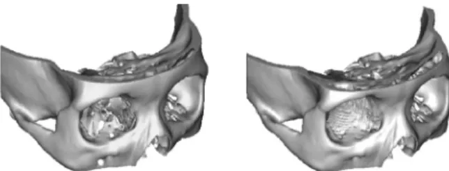
In 2014, there was one patient with skull defect reconstruct-ed by using custom-made 3D titanium implant. Custom-made 3D titanium implant was manufactured by Medyssey Co., Ltd. using 3D CT data, Mimics software, and an EBM (Electron Beam Melting) machine. CT was scanned with 1mm thickness and the data was investigated from the bone part of axial, sag-ittal and coronal plane. After then, 3D image was produced and implant was designed for the defect (Fig. 1). In designing process, the manufacturer and surgeon discussed the position of fixation, the amount of porosity and the figure of implant. When the manufacturing of the 3D implant was completed, the surgeon simulated the operation with it to the patient’s rapid prototyping (RP) model (Fig. 2).
ISSN 2383-5389
C
ase Report
The Manufacture of Custom Made 3D Titanium Implant
for Skull Reconstruction
Hyung Rok Cho, M.D.1, In Sik Yun, M.D., Ph.D.2, Kyu Won Shim, M.D., Ph.D.3, Tai Suk Roh, M.D., Ph.D.2, Yong Oock Kim, M.D., Ph.D.1
1Department of Plastic & Reconstructive Surgery, Institute for Human Tissue Restoration, Yonsei University College of Medicine, Seoul,
Korea
2Department of Plastic & Reconstructive Surgery, Gangnam Severance Hospital, Yonsei University College of Medicine, Seoul, Korea
3Department of Neurosurgery, Yonsei University College of Medicine, Seoul, Korea
Nowadays, with advanced 3D printing techniques, the custom-made implant can be manufactured for the patient. Especially in skull reconstruction, it is difficult to design the implant due to complicated geometry. In large defect, an autograft is inappropriate to cover the defect due to donor morbidity. We present the process of manufacturing the 3D custom-made implant for skull re-construction. There was one patient with skull defect repaired using custom-made 3D titanium implant in the plastic and recon-structive surgery department. The patient had defect of the left parieto-temporal area after craniectomy due to traumatic subdural hematoma. Custom-made 3D titanium implants were manufactured by Medyssey Co., Ltd. using 3D CT data, Mimics software and an EBM (Electron Beam Melting) machine. The engineer and surgeon reviewed several different designs and simulated a mock surgery on 3D skull model. During the operation, the custom-made implant was fit to the defect properly without dead space. The operative site healed without any specific complications. In skull reconstruction, autograft has been the treatment of choice. However, it is not always available and depends on the size of defect and donor morbidity. As 3D printing technique has been advanced, it is useful to manufacture custom-made implant for skull reconstruction.
Key WordsZZSkull reconstruction ㆍCustom-made implant.
Received: July 5, 2014 / Revised: July 11, 2014 / Accepted: July 15, 2014 Address for correspondence: In Sik Yun, M.D.
Department of Plastic & Reconstructive Surgery, Gangnam Severance Hospital, 211 Eonju-ro, Seoul, Korea Tel: 02-2019-3423, Fax: 02-577-4914, E-mail: [email protected]
Journal of International Society for Simulation Surgery█ 2014;1(1):13-15
Case Report
During the operation, we were able to confirm the custom-made 3D implant was exact fit for the skull defect without leav-ing any dead spaces. There was no complication on the opera-tive wound and the depressed scalp was recovered. Patient satisfied with their result and postoperative facial CT was eval-uated to confirm the position of implant.
Case 1
The patient was a 21-year-old female with a calvarial defect in the left parieto-temporal area. She had a traffic accident and epidural hemorrhage was found. Craniectomy and cranioplas-ty with MedPor® was done. However, the implant had been re-moved due to infection. The defect size was 15×15 (cm2) and re-construction was done with 3D titanium mesh. The postoperative
follow-up was two months without complications (Fig. 3).
Discussion
We reconstructed one case of calvarial defect successfully with custom-made 3D titanium implant. Although it was just one case and we did not look at the long term follow-up, cus-tom-made implants can be considered a good option for skull reconstruction. The advantages such as the short operating time, no required special surgical techniques, and no donor site morbidity were well known.
In calvarial reconstructions, autograft was widely used among the many kinds of grafts. It is good for an osteoconduc-tion.4 However, it cannot be used in large defects and can cause
donor site morbidity. Also, its result depends on the harvesting technique and the incidence rate of bone resorption ranges from 3% to 12%.5-7 When resorption occurs, secondary
opera-tion is inevitable to compensate for the alteraopera-tion.8,9
Titanium is strong enough to resist secondary trauma while providing maximal stability. Furthermore, it generally causes less inflammation, bonds with surrounding mineralized bone and has a biocompatibility.10-12 However, due to its hardness, it is
necessary to prefabricate the implant using computer-assisted design and manufacturing. A major concern in calvarial re-construction has been the complex geometry which can affect preoperative planning and aesthetic outcome.13 With advanced
technology, computer-assisted designed titanium implants were introduced.14 In our cases, the implants exactly fit the
de-fect and properly covered the dede-fect area without dead space. This study has limitations, such as its small sample size and early follow-up. However, there was no complication and the patient was satisfied with their outcome functionally and aes-thetically.
Fig. 1. 3D implant design process. 3D reconstruction of data was
performed and implant was designed.
Fig. 2. Custom-made 3D titanium implants were manufactured by
EBM (Electron Beam Melting) machine.
Fig. 3. Case 1. Preoperative 3D facial CT (Left), Postoperative
The Manufacture of Custom Made 3D Titanium Implant for Skull Reconstruction █Cho HR, et al
Conclusion
Short operation time, exactly fitness to the defect and cos-metic outcome are advantages of this 3D printing method. In these aspects, custom-made 3D implants can be one of the best options for skull reconstruction.
REFERENCES
1. Ono, I., Tateshita, T., Satou, M., Sasaki, T., Matsumoto, M. and Kodama, N. Treatment of large complex cranial bone defects by using hydroxyapatite ceramic implants. Plast. Reconstr. Surg. 1997; 104: 339
2. Eppley, B. L., Kilgo, M., and Coleman, J. J. Cranial reconstruction with computer-generated hard-tissue replacement patient-matched implants: Indications, surgical technique, and long-term follow-up. Plast. Reconstr. Surg. 2002;109: 864
3. D’Urso, P. S., Earwaker, W. J., Barker, T. M., M. J. Redmond, R. G. Thompson, D. J. Effeney, F. H. Tomlinson. Custom cranioplasty us-ing stereolithography and acrylic. Br. J. Plast. Surg. 2000; 53: 200 4. Uwe Spetzger, Vassilios Vougioukas, Jorg schipper. Materials and
techniques for osseous skull reconstruction. Minimally Invasive Therapy. 2010;19:110-121
5. Aarabi B, Hesdorffer DC, Ahn ES, Aresco C, Scalea TM, Eisenberg HM. Outcome following decompressive craniectomy for malignant
swelling due to severe head injury. J Neurosurg 2006;104:469 6. Figaji AA, Fieggen AG, Peter JC: Early decompressive craniotomy
in children with severe traumatic brain injury. Childs Nerv Syst 2003; 19:666
7. Kan P, Amini A, Hansen K, White GL Jr, Brockmeyer DL, Walker ML, Kestle JR. Outcomes after decompressive craniectomy for se-vere traumatic brain injury in children. J Neurosurg 2006;105:337 8. Moreira-Gonzalez A, Jackson IT, Miyawaki T, et al: Clinical
out-come in cranioplasty: Critical review in long-term followup. J Cra-niofac Surg 2003;14:144
9. Grant GA, Jolley M, Ellenbogen RG, Roberts TS, Gruss JR, Loeser JD. Failure of autologous bone-assisted cranioplasty following de-compressive craniectomy in children and adolescents. J Neurosurg 2004;100:163
10. Blake GB, MacFarlane MR, Hinton JW. Titanium in reconstruction of the skull and face. Br J Plast Surg. 1990;43:528–35.
11. Raza SM, Thai QA, Pradilla G, Tamargo RJ. Frontozygomatic titani-um cranioplasty in frontosphenotemporal pterional craniotomy. Neurosurgery 2008;62:262–5.
12. Peter C. Neligan, Geoffrey C. Gurtner, Plastic Surgery, 3rd ed. New York: ELSEVIER; 2013. Vol 1.p787
13. Holck, D. E., Boyd, E. M., Hg, J., and Mauffray, R. O. Benefits of ste-reolithography in orbital reconstruction. Ophthalmology 106: 1214, 1999.
14. Winder, J., Cooke, R. S., Gray, J., Fannin, T., and Fegan, T. Medical rapid prototyping and 3D CT in the manufacturer of custom made cranial titanium plates. J. Med. Eng. Tech.1999; 23: 26
Journal of International Society for Simulation Surgery 2014;1(1):16-18
서 론
악안면골 중에서도 특히 안와골은 시력을 담당하는 안와를 감싸고 있는 뼈로, 그 모양이 상하좌우가 모두 다른 독특한 해 부학적 특징을 가지고 있다. 내측벽은 우리 몸의 뼈 중 가장 얇은 뼈로 안와에 대한 외부 충격에 대해 쉽게 부서져서 안와 자체의 파열을 방지하는 역할을 하며, 하벽 또한 비교적 얇은 뼈로 형성 되어 내측벽과 함께 안와 자체의 파열을 방지함과 동시에 안와 를 수직적으로 지탱한다. 외측벽과 상벽은 비교적 두꺼운 관골 과 전두골이 주를 이루며 외부로 부터의 충격으로부터 안와 자 체를 보호하는 역할을 함께 수행한다.1,2 이러한 안와골은 흔히 안와 파열 골절이라는 메커니즘으로 손상받게 되는데, 이는 안 와에 직접적인 타격이 이루어질 경우 주로 내측벽과 하벽이 부 서지면서 안와 자체의 파열을 방지하면 발생한다. 이러한 안와 파열골절의 경우 뼈 자체의 두께가 워낙 얇아서 기존의 골절된 뼈로는 재건이 쉽지 않으며, 따라서 인조뼈 형태의 물질로 기존 의 골절된 뼈를 대체하여 수술하는 방식이 일반적이다.3-6 하지만 이러한 안와파열 골절 복원 수술에 있어 안와골의 복 잡한 형태로 인해 조금만 잘못 복원이 되어도 환자는 쉽게 안구 함몰 증상이 나타날 수 있으며 이는 추가적인 수술로도 복원이 매우 힘든 상황 중에 하나에 속한다. 또한 안구를 움직이는 6개 의 안와주변 근육이 제대로 재배치되지 못하면 복시 등의 증상 으로 큰 불편함을 야기하게 된다.7,8 이러한 정확한 재건수술을 위해 최근 각광받고 있는 것이 3 차원 컴퓨터 시뮬레이션이다. 컴퓨터 시뮬레이션 이미지가 실제 수술에 적용되기 위해서는 surgical guide 형태의 매개체가 필 ISSN 2383-5389Application of 3D Simulation Surgery to Orbital Wall
Fracture : A preliminary Case Study
Jong-Woo Choi, M.D., Ph.D., M.M.M.
Department of Plastic and Reconstructive Surgery, College of Medicine, Ulsan University, Seoul Asan Medical Center, Seoul, Korea
The orbit has a very special anatomical structure. The complex anatomical structure should be restored when we encounter the patient with orbital wall fracture. Unless these specific anatomy were reconstructed well, the patient should suffer from various complications such enophthalmos, diplopia or orbital deformity. In addition, because the patient has a his own specific orbital shape, individualized approach will be necessary. The aim of this trial is to try to restore the original orbit anatomy as possible based on the mirrored three dimensional CT images based on the computer simulation. Preoperative computed tomography (CT) data were processed for the patient and a rapid prototyping (RP) model was produced. At the same time, the uninjured side was mirrored and superimposed onto the traumatized side, to create a mirror-image of the RP model. In order to restore the missing skipped images between the cuts of CT data because of the thinness of the orbital walls, we manipulated the DICOM data for im-aging the original orbital contour using the preoperatively manufactured mirror-image of the RP model. And we fabricated Tita-nium-Medpor to reconstruct three-dimensional orbital structure intraoperatively. This prefabricated TitaTita-nium-Medpor was then inserted onto the defected orbital wall and fixed. Three dimensional approach based on the computer simulation turned out to be very successful in this patient. Individualized approach for each patient could be an ideal way to manage the traumatic patients in near future.
Key WordsZZOrbital wall fracture ㆍThree-dimensional surgery ㆍBlow out fracture ㆍPre-surgical simulation ㆍ Three-dimensional simulation.
Received: July 8, 2014 / Revised: July 11, 2014 / Accepted: July 15, 2014 Address for correspondence: Jong-Woo Choi, M.D., Ph.D., M.M.M.
Department of Plastic and Reconstructive Surgery, Seoul Asan Medical Center, PungNapDong, SongPaGu, Seoul, Korea Tel: 02-3010-3604, Fax: 02-476-7471, E-mail: [email protected]
Application of 3D Simulation Surgery to Orbital Wall Fracture : A Preliminary Case Study █Choi JW 요한데, 안와 파열 골절에 있어서는 기존의 골절된 뼈를 대체하 는 다양한 임플란트들이 그 역할을 담당할 수 있다. 또한 이러 한 컴퓨터 시뮬레이션을 위해서는 기준이 되는 이미지가 필요한 데, 안와골절 복원 수술의 경우 반대편 건측 안와가 이러한 기 준 역할을 수행할 수 있다고 판단된다. 따라서 저자들은 이러한 안와파열 골절에 있어 반대편 정상 안와의 CT data를 mirroring을 이용하여 재건하여 이를 통해 Rapid prototype을 작성하고 이에 맞추어 안와파열 골절 복원 수술을 하여 환자가 가진 원래의 안와 모양을 최대한 이상적으 로 복원시키고자 시도하였다.
증례 보고
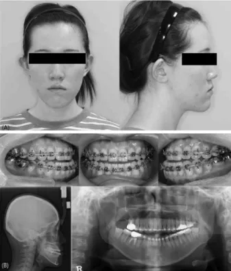
42세의 여자 환자가 넘어짐을 통한 우측 안와하벽골절을 주 소로 본과에 내원하였다. 이에 CT 촬영을 포함한 통상의 술전 검사를 시행하였으며 3차원 물체로 재구성한 환자의 두개안면 골에 대해 악안면기형 진단 및 분석을 시행하였다. 삼차원 CT scan을 촬영하였고, CT data를 Simplant (simplant pro, MaterialsⓇ, Belgium)를 이용하여 분석한 후 컴퓨터 시뮬레이 션 수술을 계획하였다(Fig. 1).
CT DICOM 파일을 기반으로 환자의 안와골을 3차원 물체로
재구성 하였으며, 좌측의 정상안와형태의 CT data를 mirror-ing 기법 (Mimics Z software : Materialize, Leuven, Bel-gium)을 이용하여 우측에도 적용하여 환자가 다치기 전의 양측 안와골의 CT 이미지를 얻었다. 이를 3D 프린팅을 통해 제작함 으로써 실제 수술 중 안와파열 골절을 복원하기 위한 Titani-um-Medpore implant을 위치 시키기 위한 기준으로 사용하였 다 (Fig. 2). 제작된 3차원 Rapid Prototype을 이용하여 통상의 안와파 열 골절 복원수술을 진행하였으며 transconjunctival prese-ptal approach를 이용하여 하안와연을 노출시키고, 하안와 신 경을 하벽으로부터 bipolar coagulator를 이용하여 박리하였 다. 3차원 컴퓨터 시뮬레이션을 이용해 제작한 Rapid proto-type mirroring model의 안와골에 맞추어서 사전에 제작하여 둔 Titanium Mepore implant를 삽입하여 안와골을 복원하 였다. 환자는 수술 후 안구 함몰이나 복시 등의 합병증이 발생 하지 않았으며, 특이한 문제 없이 술 후 3일째 퇴원하였다. 술 후 3일째 6개월째 술후 CT scan을 통해 수상전과 유사하게 복 원되었음을 확인할 수 있었다 (Fig. 3).
고 찰
안면골의 형태는 각 개인, 인종, 성별에 따라 다른 것으로 알 려져 있으며, 안와골 역시 각 개인마다 조금씩 그 크기가 뼈의 위치 및 각도가 다르다. 하지만, 지금까지 일반적으로 수술을 함 에 있어 이러한 환자 개인의 차이가 수술에 반영되기는 어려웠 다. 특히나, 안와골절 복원 수술의 경우에는 절대 손상이 되어 서는 안 되는 시신경과 인접되어 수술이 진행되어야 하고, 수술 시야가 좋지 않아 이러한 주변 안와골의 모양을 충분히 노출 시 킨 후 수술을 하는 것이 현실적으로 쉽지 않다. 따라서 이러한 안와 파열 골절의 복원을 위해 사용되는 임플란트의 경우에는 미리 그 모양을 제작하여 삽입하는 형태로 수술이 진행될 수 있 다면 가장 이상적이다. 하지만, 이러한 사전 제작을 위해서는 환 자의 원래 안와골의 형태를 알 수 있어야 하는데, 동측은 이미Fig. 1. The CT scan coronal image of the patient with inferior
or-bital wall fracture.
Fig. 3. Postoperative CT coronal image.
Journal of International Society for Simulation Surgery█ 2014;1(1):16-18 골절이 되어 정확한 이미지를 얻을 수 없으므로, 반대편 건측 안 와골이 가장 좋은 대안이 될 것이다. 이를 이용한 기법이 Mir-roring technique이다. 본 증례에서 우측 안와 하벽골절의 복원을 위해 이 미러링 기 법을 이용하였는데, 만족할 만한 결과를 얻을 수 있었다. 이는 통상 대부분의 경우 양측 얼굴이 2mm 이내의 대칭성을 가지고 있는 것으로 알려져 있고, 반대측 건측이 가장 좋은 landmark 가 될 수 있기 때문이다. 문제는 CT촬영을 통해 이러한 안와골 의 거울영상을 획득하더라도 안와골이 통상 매우 얇은 뼈로 이 루어져 있어서, 안와골이 CT 영상에 skip 되어 결손 형태로 Rapid Prototype이 제작되는 것이다. 이러한 문제를 해결하기 위해 저자들은 3차원 컴퓨터 시뮬레이션 조작을 통해 skip된 CT image를 연결하는 기법을 이용하여 결손부위 없는 연속성 있는 안와골 RP model을 제작할 수 있었다. 이는 수술 시 사용 하게 되는 Titanium-Medpore implant의 이상적인 곡면을 만 드는데 있어 필수적이었으며, 매우 유용하였다. 또한, Titanium-Medpore implant를 이용하여 안와벽을 재건함으로써 술후 CT scan에서 반대편 건측과 유사하게 우측 의 안와 하벽이 잘 재건되었음을 확인할 수 있었고, 본 거울영 상을 이용한 3차원 컴퓨터 시뮬레이션 기법을 이용해 환자 본인 의 안와골을 최대한 원래에 가깝게 복원할 수 있었으며, 이러한 접근은 미래의 individualized medicine의 현실적인 접근방법 의 하나로 간주 될 수 있을 것으로 판단된다.
결 론
안와파열 골절은 전통적으로 술자의 경험에 의존하여 주변 안와골을 노출 시킨 후, 결손 부위를 다양한 임플란트로 대체 하는 형태의 수술이 주로 이루어져왔으나, 실제 안와골의 복잡 한 안와골 형태가 재건되지 못하면, 안구함몰, 복시 등의 심각한 합병증이 발생함을 감안하였을 때, 이러한 3차원 컴퓨터 시뮬레 이션을 이용한 안와재건은 individualized medicine의 첫걸음 이자, 매우 유용한 이상적인 수술 방식임을 확인 할 수 있었다.참 고 문 헌
1. Kakizaki H, Takahashi Y, Asamoto K, Nakano T, Selva D, Leibo-vitch I. Anatomy of the superior border of the lateral orbital wall: surgical implications in deep lateral orbital wall decompression surgery. Ophthalmic plastic and reconstructive surgery. 2011 Jan-Feb;27(1):60-3. PubMed PMID: 20736872
2. Beden U, Edizer M, Elmali M, Icten N, Gungor I, Sullu Y, et al. Surgical anatomy of the deep lateral orbital wall. European journal of ophthalmology. 2007 May-Jun;17(3):281-6. PubMed PMID: 17534804
3. Oh SA, Aum JH, Kang DH, Gu JH. Change of the orbital volume ratio in pure blow-out fractures depending on fracture location. The Journal of craniofacial surgery. 2013 Jul;24(4):1083-7. PubMed PMID: 23851745
4. Lee H, Ahn J, Lee TE, Lee JM, Shin H, Chi M, et al. Clinical char-acteristics and treatment of blow-out fracture accompanied by can-alicular laceration. The Journal of craniofacial surgery. 2012 Sep;23(5):1399-403. PubMed PMID: 22948636
5. Lee S, Yen MT. White-eyed blow-out fracture. Journal of pediatric ophthalmology and strabismus. 2011 Sep-Oct;48(5):320. PubMed PMID: 21913629
6. Park JS, Lew H, Lee SY. Role of inferior orbital wall morphologic properties in isolated orbital blow-out fracture. Ophthalmic re-search. 2012;47(1):1-6. PubMed PMID: 21691135
7. Hayakawa I. [Surgical treatment of the orbital blow-out fracture (author's transl)]. No shinkei geka Neurological surgery. 1976 Oct;4(10):933-40. PubMed PMID: 1033468
8. Kugelberg U. Diplopia in down-gaze after a blow-out fracture. Acta ophthalmologica Scandinavica. 1998 Oct;76(5):629-31. PubMed PMID: 9826057
Journal of International Society for Simulation Surgery 2014;1(1):19-22
서 론
3차원 영상 재건기술 (3-Dimensional image reconstruc-tion)을 이용한 생체역학 연구는 1970년대에 최초로 시도되었으 며, 컴퓨터단층촬영 (Computed Tomography, CT)을 이용한 3차원 영상 재건기술은 1980년대 보고되기 시작하여 최근까지 매우 다양한 분야에서 이용되고 있다. 컴퓨터 시뮬레이션을 이용 한 3차원 영상은 상대적으로 적은 비용과 시간을 사용하여 실제 시행하기 불가능한 실험을 시행할 수 있고 해부학적 구조에 대한 교육에 이용할 수 있으며 생체내의 역학적 특성에 대한 정보를 제공한다. 또한 얻을 수 있는 데이터의 종류가 많고 동일한 조건 에서 다양한 상황을 연출하여 결과를 얻을 수 있는 장점이 있다.1 특히 정형외과 슬관절 영역중에서 인공관절치환술 및 인대재건 술에 있어서 역학적 기능의 영향을 규명하거나 실제 수술에 사 용될 정보를 제공함으로써 실제 수술에 앞서 수술 예비계획의 목적으로도 사용될 수 있다. 본 종설에서는 슬관절 인대재건술 영역에서 사용되는 3차원 영상 기술에 대하여 보고하고자 한다.
슬관절 전방십자인대 재건술
전방십자인대 손상은 정형외과 스포츠 외상중에서 가장 흔히 발생하는 손상 중 하나이다. 스포츠 인구 및 각종 사고의 증가 로 인하여 전방십자인대 손상 환자의 빈도는 증가하고 있으며, 미국정형외과학회의 통계에 따르면 연간 10만건의 전방십자인대 재건술이 시행되고 있고, 한국 건강심사보험평가원의 자료에 따 르면 연간 14690건의 전방십자인대 재건술이 시행된다고 보고 되고 있다. 최근의 임상적인 연구에 의하면 전방십자인대 재건 술 이후 만족스러운 결과가 보고되고 있으나, 전반적인 기술의 발전과 함께 전방십자인대 손상 이전의 상태로 돌아가려는 환자 의 욕구 또한 매우 높기 때문에 해부학적으로 정확하며, 정상적 인 전방십자인대의 기능에 가까운 재건술을 시행하기 위한 노력 이 필요하다.2,3 전방십자인대 손상에 대해 주로 전내측 다발만을 재건하는 단일 다발 전방십자인대 재건술이 시행되어 비교적 좋은 결과들 이 보고되고 있다. 슬관절의 운동에 따라 전방십자인대의 길이 ISSN 2383-5389R
eview
Three-dimensional Reconstruction of the Knee for
Ligament Reconstruction
Sung-Hwan Kim, M.D., Seung-Joo Ha, M.D.
Arthroscopy & Joint Research Institute and Department of Orthopedic Surgery, Yonsei University College of Medicine, Seoul, Korea
As computer technology develops and this is applied to medical image field , three dimensional image reconstruction technology using computer simulation is utilized in various categories that include anatomical study and biomechanics study of human body.
Especially orthopedic surgeons are able to investigate biomechanical function and be provided information for operations with this technology in terms of ligament reconstruction of knee. And this technology can be utilized in preparing preoperative plan-ning and instructions and traiplan-ning. This review is about three dimensional image reconstruction technology which is utilized in ligament reconstruction of knee.
Key WordsZZThree-dimensional Reconstruction ㆍLigament ㆍKnee.
Received: July 9, 2014 / Revised: July 11, 2014 / Accepted: July 15, 2014 Address for correspondence: Sung-Hwan Kim, M.D.
Department of Orthopaedic Surgery, Yonsei University College of Medicine, 50-1 Yonsei-ro, Seodaemun-gu, Seoul, Korea Tel: 02-2228-2184, Fax: 02-363-1139, E-mail: [email protected]
Journal of International Society for Simulation Surgery█ 2014;1(1):19-22 가 변하지 않는 등장성 대퇴 부착부는 해부학적 대퇴 부착부와 다르다고 알려져 있으나, 일부 사체 실험에서는 해부학적 대퇴 부착부와 등장성 대퇴 부착부가 일치한다는 보고도 있다.4,5 전 내측 다발은 관절 운동에 따라 길이 변화가 비교적 적은 것으로 알려져 있다. Boisgard 등6 은 자기공명영상장치 (Magnetic Resonance Imaging, MRI)를 이용한 3차원 영상 재건 기술 을 이용하여 관절 운동에 따른 전내측 다발 및 후외측 다발의 길이 변화를 측정하였다. 저자들은 전내측 다발이 후외측 다발 에 비해 길이 변화가 적다고 보고하였고 이를 바탕으로 전방십 자인대 재건술을 시행함에 있어 참고로 할 수 있다고 하였다. 그 러나 전내측 다발의 재건을 목표로하는 단일 다발 재건술은 전 후방 불안정성 및 회전 불안정성이 동반될 수 있으므로7 최근에 는 대퇴터널을 해부학적인 위치에 만들기 위해 노력을 하고 있으 며, 이중 다발 전방십자인대 재건술을 이용하여 두가지를 모두 교정하려는 방법이 시도되고 있다. 대퇴 터널의 전후방 위치는 전방십자인대 재건술의 전후방 불 안정성 실패를 결정하는 중요한 인자가 되는데, 이 때 Resident’ s ridge를 확인하는 것이 중요하다.8-10 이를 위해Roh등11은 다 중채널컴퓨터단층촬영 (Multi-Detector Computed Tomog-raphy, MDCT)을 이용하여 3차원 재구성 분석을 시행하였며, 대 퇴골 후방 피질골로부터 7.6 ± 2.6mm 지점에 8.2 ± 2.6mm 의 길이와 3.5 ± 1.5mm 높이를 갖는 Resident’s ridge가 존재 하고 과간 절흔의 후벽에서 약 30% 앞쪽에 위치한다고 보고하 였다. 이를 통해 수술 중 보다 정확한 대퇴 터널의 위치를 만들 수 있다고 하였다. 전방십자인대의 해부학적 대퇴 부착부는 여 러 3차원 영상 재건 기술을 이용한 연구에서 그 위치가 밝혀졌 는데9,12,13 Iwahashi 등14에 의하면 3차원 영상 재건 기술로 확 인한 전방십자인대의 대퇴부착부는 Resident’s ridge와 대퇴 외과의 관절연골 사이에 위치하며 128.3 ± 10.5mm2 면적을 차지한다고 보고하면서 3차원 영상 재건 기술이 전방십자인대 를 해부학적 위치에 정확히 위치시키는데 많은 도움이 된다고 하였다. 이중 다발 재건술은 전방십자인대의 전내측 다발과 후외측 다발의 해부학적 부착부에 위치하도록 대퇴 터널을 만들기 때문 에 단일 다발 재건술에 비해 이론적으로는해부학적 및 생역학적 측면에서 장점을 가지고 있다고 알려져 있다. Inoue 등15 은 3차 원 컴퓨터단층촬영을이용하여 3차원 영상 재건술을 시행하고 여기에 터널의 위치가 보이도록 투명도를 높인 T-3DCT 소프트 웨어를 개발하여 보다 정확히 터널의 위치를 평가할 수 있도록 하였다. 그러나 1983년 Mott6 에 의해 이중 다발 재건술이 처음 소개된 이후 현재까지 보고된 문헌에 의하면 이중 다발 재건술 이 단일 다발 재건술에 비해 뛰어난 임상적 결과를 보여주지 못 한다고 알려져 있다. Taketomi 등16 은 최근에 3차원 투시 방사 선 촬영 내비게이션 장치 (3D fluoroscopic navigation)를 이 용하여 전방십자인대의 해부학적 대퇴 부착부에 대퇴 터널을 만 들어 이중 다발 재건술을 시행하였고, 수술 후3차원 컴퓨터 단 층 촬영 장치를 이용하여 대퇴 터널의 적정성 및 이에 따른 임상 적 평가를 하여 단기 추시상 좋은 결과를 얻었다고 보고하였다. 그러나 Markolf 등17은 사체를 이용한 시뮬레이션된 축이동검사
(pivot shift test)를 진행하여 단일 다발 재건술만으로도 정상
적인 슬관절 생역학의 회복이 가능하다고 하였으며, Kondo 등18 및 Tsuda 등19 은 대퇴 터널의 위치를 보다 외측으로 시행하는 경우 회전 안정성 회복에 대하여 단일 다발 재건술과 이중 다발 재건술 사이의 차이가 없을 것이라고 하였다. 대퇴 터널의 위치 를 외측으로 시행하기 위해서는 기존에 사용되었던 경골 터널 형성 술기 (transtibial technique)보다는 전내측 삽입구 형성 술기 (transportal technique)가 더 유리한 것으로 알려져 있 다. Kopf 등20 은 경골 터널 형성 술기로 만들어진 대퇴 터널을 3 차원컴퓨터단층촬영 장치를 이용하여 분석하였는데, 해부학적 대퇴 부착부보다 전방에 터널이 형성되기 때문에 해부학적 부착 부에 터널을 만들기 위해서는 다른 수술적 방법을 고려할 것으 로 권유하였다. 또한 Tashiro 등21 은 3차원 컴퓨터 지원 설계 (3D-Computer Aided Design, 3D-CAD) 모델을 이용하여 경골 터널 형성 술기에 비해 전내측 삽입구 형성 술기가 보다 정 확한 해부학적 위치에 터널을 만들 수 있으며, 타원형의 터널 입 구를 피할 수 있다고 하였다.
슬관절 후방십자인대 및
후외측 구조물 재건술
후방십자인대 손상은 전방십자인대 손상에 비하여 그 발생빈 도는 낮지만, 전방십자인대에서처럼 스포츠 인구 및 교통 사고 등의 증가로 인해 발생빈도가 점차 증가하는 추세이다. 후방십 자인대 단독 손상은 드물며, 슬관절의 기타 인대 손상이 동반되 는 경우가 많기 때문에 후방 및 후외측 불안정성과 외회전 및 내반 불안정성이 발생하게 된다. 그러나 아직까지 후방십자인대 를 포함한 슬관절의 후외측 구조물에 대한 3차원 영상 재건 기 술을 이용한 문헌 보고는 전방십자인대의 그것에 비해 부족하다 고 할 수 있다. 증상이 없는 급성의 단독 후방십자인대 손상에서는 보존적 치료를 시도할 수도 있지만, 고도의 후방 전위, 동반된 인대 손 상, 증상이 있는 만성 후방십자인대 손상의 경우에는 하지 정렬 축의 부정정렬을 유발하고, 이로 인한 관절면의 퇴행성 변화를 유발할 수 있기 때문에 수술적 치료가 권장되고 있다.22,23 후방Three-dimensional Reconstruction of the Knee for Ligament Reconstruction █Kim SH , et al 십자인대 재건술에서 경골 터널의 위치보다 대퇴 터널의 위치를 정확히 하는 것이 슬관절의 운동역학을 회복하는데 중요하다고 보고되었다.24 이를 위해 과거에는 사체 실험이나 이차원적인 방 사선 사진을 이용하였으나 이러한 방법으로는 대퇴 부착부의 후 방십자인대의 구조적 복잡성으로 인해 해부학적 경골 터널을 정 확히 판단하기가 어려웠다. 그러나 최근 3차원 영상 재건 기술 이 발달함에 따라서 대퇴 부착부와 후방십자인대의 생역학에 대해 보다 정확히 이해할 수 있게 되었다. Westermann 등25 은 컴퓨터단층촬영 장치를 이용한 3차원 영상 재건 기술을 사용하여 후방십자인대의 해부학적 부착부위 를 나타내었고, 이를 통해 Footprint-overlap mappig기술을 이용하여 각기 다른 표본에서 검출된 대퇴 부착부위를 한개의 대퇴골 모형에 표현하였다. 저자들에 따르면 후방십자인대 대퇴 부착부의 중심은 과간 절흔의 천장에서 25% 하방, 전방 대퇴과 에서 38% 되는 지점에 있다고 하였다. Covey 등26이 시행한 해 부학적 및 생역학적 연구에서 후방십자인대 대퇴 부착부의 등장 점은 해부학적 부착부의 5~15% 만 차지하며, 대부분은 비등장 점에 부착되어 있다고 보고되었다. 또한 등장점에 대퇴 터널을 형성할 경우 45° 이상의 슬관절 굴곡상태에서는 후방 전위가 일 어난다는 보고도 있다.27 생역학적인 연구에 따르면 정상적인 후 방십자인대에서 전외측 다발이 슬관절의 후방 전위를 막아주는 역할을 한다고 알려져있어28 전외측 다발의 재건을 목표로하는 단일 다발 재건술이 시행되었다. 그러나 단일 다발 재건술 시행 후에도 30° 미만의 슬관절 굴곡시에 후방 전위가 발생할 수 있 으며, 90° 이상의 슬관절 굴곡시에는 회전 불안정성이 나타날 수 있다고 보고29 가 되면서 전방십자인대의 경우처럼 이중 다발 재건술에 대한 필요성도 제기되었다. Yoon 등30은 3차원 유한요
소법 (finite element method)을 이용하여 단일 다발 재건술, 이중 다발 재건술, 인대 잔유물 보존 이중 다발 재건술의 경우 를 비교하였고, 이중 다발 보강 재건술을 시행한 경우가 후방 및 회전 안정성에 가장 우수한 것으로 보고하였다. 후외측 구조 물 손상이 동반된 만성 후방십자인대 손상에서는 하지 정렬축 을 교정하기 위해 개방적 경골 절골술을 시행한다. Petriglia-no 등31 은 3차원 영상 재건기술및생역학적연구를통해 이러한 개방적 경골 절골술을 시행하게 되면 관상면에서의 하지 정렬 축이 교정될 뿐만 아니라 시상면에서의 경골후경사각이 증가하 게되어 후방안정성에 기여를 한다고 보고하였다.
결 론
1970년대 이래로 3차원 컴퓨터 영상 재건 기술이 의학 영상 기술과 접목이 되면서 많은 발전을 이루었다. 3차원 영상 재건 기술은 인체의 해부학적 구조 및 생역학적인 기능에 대하여 보 다 방대하고 자세한 연구를 가능하게 하였다.특히 비침습적인 방법으로 반복적인 결과를 도출할 수 있기 때문에 이전의 사체 실험이나 2차원 영상 이미지를 이용하여 시행되었던 연구에 비 해 시간과 비용 측면에서의 장점을 지니고 있다. 또한 Yeom 등 32 은 3차원 영상 재건 기술을 이용하여 환자의 슬관절 실물 조 형 모델을 제작하고, 이를 통해 초심자들의 교육 및 훈련에 유 용하게 사용할 수 있다고 하였다. 따라서 3차원 영상재건 기술 은 인체의 생역학적인 정보제공뿐만 아니라 수술 전 계획 및 훈 련에 이르기까지 다양한 분야에서 활용될 수 있을 것으로 생각 된다.참 고 문 헌
1. Pena E, Calvo B, Martinez MA, Doblare M. A three-dimensional finite element analysis of the combined behavior of ligaments and menisci in the healthy human knee joint. J Biomech 2006; 39(9):1686-1701
2. Meredick RB, Vance KJ, Appleby D, Lubowitz JH. Outcome of single-bundle versus double-bundle reconstruction of the anterior cruciate ligament: a meta-analysis. Am J Sports Med 2008; 36(7):1414-1421
3. Irrgang JJ, Bost JE, Fu FH. Re: Outcome of single-bundle versus double-bundle reconstruction of the anterior cruciate ligament: a meta-analysis. Am J Sports Med 2009;37(2):421-422; author reply 422
4. Hoogland T, Hillen B. Intra-articular reconstruction of the anterior cruciate ligament. An experimental study of length changes in dif-ferent ligament reconstructions. Clin Orthop Relat Res 1984(185):197-202
5. Schutzer SF, Christen S, Jakob RP. Further observations on the isometricity of the anterior cruciate ligament. An anatomical study using a 6-mm diameter replacement. Clin Orthop Relat Res 1989(242):247-255
6. Boisgard S, Levai JP, Geiger B, Saidane K, Landjerit B. Study of the variations in length of the anterior cruciate ligament during flexion of the knee: use of a 3D model reconstructed from MRI sections. Surg Radiol Anat 1999;21(5):313-317
7. Colombet P, Robinson J, Christel P, Franceschi JP, Djian P. Using navigation to measure rotation kinematics during ACL reconstruc-tion. Clin Orthop Relat Res 2007;454:59-65
8. Fu FH, Jordan SS. The lateral intercondylar ridge--a key to ana-tomic anterior cruciate ligament reconstruction. J Bone Joint Surg Am 2007;89(10):2103-2104
9. Purnell ML, Larson AI, Clancy W. Anterior cruciate ligament in-sertions on the tibia and femur and their relationships to critical bony landmarks using high-resolution volume-rendering computed tomography. Am J Sports Med 2008;36(11):2083-2090
10. Hutchinson MR, Ash SA. Resident's ridge: assessing the cortical thickness of the lateral wall and roof of the intercondylar notch. Arthroscopy 2003;19(9):931-935
11. Roh J-H, Min B-H, Park J-W, Ahn B-M. Geometry of Resident's ridge with Multidetector-Row Computed Tomograph Image. Jour-nal of Korean Arthroscopy Soc. 2008;12:40-44
12. Abreu ESGM, Oliveira MH, Maranhao GS, Deligne LD, Pfeilstic-ker RM, Novais EN, et al. Three-dimensional computed tomogra-phy evaluation of anterior cruciate ligament footprint for anatomic single-bundle reconstruction. Knee Surg Sports Traumatol