Atmospheric Correction and Velocity Aberration for Physical Sensor Modeling of High-Resolution Satellite
Images
고해상도 위성영상의 센서모델링을 위한 대기 및 속도 보정
Oh, Jaehong1)·Lee, Changno2) 오재홍·이창노
Abstract
High-resolution earth-observing satellites acquire substantial amount of geospatial images. In addition to high image quality, high-resolution satellite images (HRSI) provide unprecedented direct georegistration accuracy, which have been enabled by accurate orbit determination technology. Direct georegistration is carried out by relating the deter- mined position and attitude of camera to the ground target, i.e., projecting an image point to the earth ellipsoid using the collinearity equation. However, the apparent position of ground target is displaced due to the atmosphere and satellite velocity causing significant georegistration bias. In other words, optic ray from the earth surface to satellite cameras at 400~900km altitude refracts due to the thick atmosphere which is called atmospheric refraction. Velocity aberration is caused by high traveling speed of earth-observing satellites, approximately 7.7 km/s, relative to the earth surface. These effects should be compensated for accurate direct georegistration of HRSI. Therefore, this study presents the equation and the compensation procedure of atmospheric refraction and velocity aberration. Then, the effects are simulated at different image acquisition geometry to present how much bias is introduced. Finally, these effects are evaluated for Quickbird and WorldView-1 based on the physical sensor model.
Keywords : Georegistration, Atmospheric Refraction, Velocity Aberration, Satellite Image
1) Regular Member Researcher ETRI Electronic and Telecommunication Research Institute(E-mail:[email protected])
2) Corresponding Author Member Seoul National University of Science and Technology Civil Engineering Associate Professor (E-mail:[email protected])
1. Introduction
Many high-resolution earth-observing satellites have been currently operating to acquire substantial amount of geospatial images in high-resolution with good image quality (Stoney, 2008; Oh et al., 2010). To use the images as base map, it is important to make sure that the satellite images are assigned accurate geodetic or map coordinates, which process is geo- registration. Recent satellites provide high georegistration accuracy without any Ground Control Points (GCP), enabled by accurate orbit determination technology including DGPS, INS, and startracker. For example, Geoeye-1 provide about 5 meter of horizontal accuracy (circular error 90%) which
should be enough for medium-scale application such as loca- tion-based service (GeoEye, 2011). Exploiting the accurately determined position and attitudes of camera, the direct geo- registration is possible by relating an image point to the earth ellipsoid using the collinearity equation to compute the coor- dinates of ground targets. Note that the term ‘direct’means the georegistration rely only on the ephemeris data, not on any GCP.
In the direct georegistration, atmospheric refraction and velocity aberration must be compensated for accurate optic ray projection. Optic ray from the earth surface to satellite cameras at 400~900km altitude refracts due to the thick atmosphere which is called atmospheric refraction. The veloc-
ity aberration is caused by high traveling speed of earth- observing satellites such as approximately 7.7 km/s relative to the earth surface. Both cause apparent position displacement of ground target introducing georegistration bias. In usual generic pushbroom sensor modeling which makes correction to the exterior orientation parameters (EOP) from ephemeris data using GCP, the atmospheric refraction and velocity aber- ration are not incorporated into the modeling because the effects can be absorbed into the EOP correction terms (Kratky, 1989; Toutin, 2006). In contrast, the direct georegis- tration requires accurate determination of the atmospheric refraction and velocity aberration. However, it is not easy to find literatures describing the procedures and equations for HRSI direct georegistration though Noerdlinger (1999) inves- tigated the atmospheric refraction for Earth remote sensing application by developing an analytic method to determine the angle of the refraction assuming a spherically symmetric atmosphere.
This study investigated the ground coordinates displace- ment due to the atmospheric refraction and velocity aberration for HRSI direct georegistration. For the atmospheric refrac- tion, the Saastamoinen model (1972) was used because the approach is simple but shows reasonable accuracy LEO (Low Earth Orbit). The first test was performed for simulated data of different satellite altitudes and attitudes to check how much georegistration errors are introduced. The test showed that -2
~ +2 meters and near 10 meters of ground coordinates dis- placement can be introduced from the atmospheric refraction and velocity aberration, respectively. Then, the experiment continued for Quickbird and WorldView-1 data. The correc- tion was made to the physical sensor modeling, and the direct georegistration was compared to the RPC (Rational Polynomial Coefficients) (Grodecki, 2001) since the provided RPC already includes non-ideal imaging effects such as lens distortion, velocity aberration and atmospheric refraction.
This paper is structured as follows: in section 2, the brief direct georegistration is described including the physical sen- sor modeling, the atmospheric refraction and velocity aberra- tion. In section 3, the simulation results and the experimental results on Quickbird and WorldView-1 are presented, fol- lowed by the summary and conclusion in section 4.
2. Direct Georegistration
2.1 Physical sensor modeling (focusing on Quickbird and WorldView-1)
In the paper, the physical sensor modeling is described focusing on Quickbird/WorldView-1, which is based on the collinearity equation as the generic pushbroom model, expressed as Eq. (1). The equation is in non-linear form for computing a coordinate in the sensor frame, from a given ground coordinate in the Earth Centered Earth Fixed (ECEF) frame. Other terms can be computed using the provided Quickbird ephemeris and attitude data which contain the epoch, satellite’s position, velocity, and attitude angles for direct georegistration. Given an instant time, the exterior ori- entation parameters (EOPs) can be computed by interpolation.
The coordinates in the camera frame can be converted into the detector frame of pixel units using the camera calibration information such as the origin of the detector in the camera frame, rotation of the detector frame in the camera frame, and the pixel spacing of the detector.
(1)
Where, , , is the coordinate in the camera frame ( is the flight direction, is direction to the surface of the earth, and completes the right handed system),
is the ground point coordinate in the ECEF frame, is the satellite position in the ECEF frame (from the ephemeris file, *.eph), is the time-depen- dent rotation matrix from the ECEF frame to the body frame (from the attitude file, *.att), is the rotation matrix from the body frame to the camera frame (from the camera calibration file, *.geo), and kis the scale factor.
2.2 Projection of an image point to the ground given the ground height
The horizontal ground coordinates from a given image coordinate can be obtained by computing the intersection of the look direction from the satellite with the ellipsoid located
at an altitude h above the standard ITRF ellipsoid.
From Eq.(1), the vector from the satellite camera perspec- tive center to the ground can be expressed as Eq.(2) and the unit vector, Eq.(3), shows the apparent look direction which should be corrected for the atmospheric refraction and veloci- ty aberration.
(2)
(3)
By correcting the atmospheric refraction and velocity aber- ration (will be explained later), the corrected look direction vector, , is obtained for the direct georegistration. The ground coordinates can be simply expressed using the per- spective center of the camera and the look direction as shown in Eq.(4).
(4)
Where, is the distance from the perspective center of the satellite to the ground point to be found.
Since the ground coordinate is on the ellipsoid of the semi- major and semiminor axis , with elevation , it satisfies the ellipsoid equation Eq. and the formulation leads to solve the quadratic equation Eq.(6)
(5)
(6) Eq.(6) has two solutions, μ1, μ2. The smaller one, μmin, should be kept because the larger one is for the point on the opposite side of the ellipsoid. By introducing μmininto the equation, the ECEF coordinates of the ground point can be computed.
2.3 Atmospheric refraction
Quickbird satellite has orbit altitude of 450 km which is above the earth atmosphere. Therefore, the straight light rays
from the ground to the camera, and vice versa, bend as refrac- tive index of the atmosphere decreases with altitude. For alti- tude over 11km, Saastamoinen model (1972) expressed the constant related to atmospheric conditions as Eq.(7).
(7) [radian]
Where, H is the altitude of Quickbird camera and h is the object’s terrain elevation.
Using the constant, the correction angle is computed as Eq.(8), and the correction is made to the apparent look direc- tion for the refraction-corrected look direction vector, (see Fig. 1). Note that the off-nadir angle of the apparent look direction slightly increases from the true light ray due to the atmospheric refraction.
(8)
Where, is the angle between the look direction vector and the vector from the satellite camera to the earth’s center.
The angle correction should be made in the plane defined by the apparent look direction vector and the vector of direction to the center of the earth, i.e. rotation with respect to the orthogonal axis of the plane. For the angle correction, the ECEF frame is transformed to the coordinate frame that X axis is the direction to the center of the earth, Y axis is perpen- dicular to X axis in the plane for the angle correction, and Z Fig. 1. Atmospheric refraction and velocity aberration correction.
axis completes the right handed coordinate frame. The rota- tion matrix from the ECEF frame to the coordinate frame, , is obtained by the direction cosine, which is com- puted as Eq. (9) and (10).
(9)
(10)
Where, is the satellite position in the ECEF frame (from the ephemeris file, *.eph).
After the coordinate transformation, the atmospheric refrac- tion angle is corrected by rotating the apparent look direction vector with respect to Z axis of the transformed coordinate frame using the simple rotation matrix as shown in Eq.(11).
(11)
With
2.4 Velocity aberration
Aberration is a displacement of the apparent on-ground object from its true position due to the velocity of the satellite camera. The direction of incoming light rays from the ground is distorted as a function of the satellite’s velocity. In Fig. 1, the refraction-corrected look direction vector, , should be corrected for the refraction & aberration-corrected look direc- tion vector, using Eq.(12). Note that the satellite’s veloci- ty vector should be relative velocity vector with respect to the velocity of the ground object due to the rotation of the earth.
(12)
Where, is the speed of light and is the velocity vector
perpendicular to .
3. Experiment
3.1 Simulation
The first experiment was performed for simulated satellite’
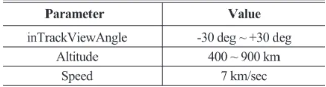
s attitudes at different altitudes to show the conventional cor- rection values of atmospheric refraction and velocity aberra- tions for HRSI. As presented in Table 1, the altitude of 400~900 km were selected because most high-resolution satellites operate at a low earth orbit. And ‘inTrack ViewAngle’, i.e. the pitch angle, was simulated -30~+30 degrees which are often used to acquire stereo images in a tra- jectory. The satellite’s descending speed was fixed to 7 km/second though it should be different depending on the alti- tude. Note that most high-resolution satellites have the speed ranging about from 6 km/sec to 8 km/sec.
Fig. 2 shows the ground coordinates displacement due to atmospheric refraction in function of inTrackViewAngle and altitude. The left figure shows the ground coordinates dis- placement ranging approximately -2 meters to +2 meters.
Note that the negative inTrackViewAngle indicates the for- ward looking in the descending satellite orbit. In other words, the look direction is from the north to the south in the descending orbit. To correct the refraction, the displacement Table 1. Simulation parameters on satellite’s attitude and altitude
Parameter Value
inTrackViewAngle -30 deg ~ +30 deg
Altitude 400 ~ 900 km
Speed 7 km/sec
Fig. 2. Ground coordinates displacement due to the atmospheric refraction in function of inTrackAngle and altitude (the right figure
shows the upper right part of the left figure).
should be subtracted from the ground coordinates of the apparent look direction vector. The right figure shows that the displacement increases for the higher altitude as expected, but the difference is relatively small such as a decimeter level.
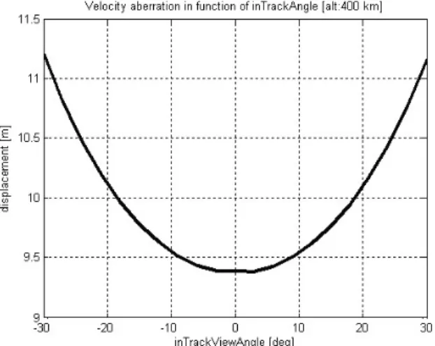
Fig. 3 shows the ground coordinates displacement due to the velocity aberration in function of inTrackViewAngle. The
ground coordinates displacement is relatively large ranging approximately 9.4 meters to 11.2 meters when compared to that of the atmospheric refraction. Note that the displacement seems large for mapping applications. As inTrackViewAngle increases, the impact of the velocity aberration on the ground coordinates displacement seems slightly larger.
3.2 Experiment on Quickbird and WorldView-1
The atmospheric refraction and velocity aberration was tested to Quickbird and WorldView-1 data, as listed in Table 2. The data processing level is Basic products which are radiometrically and sensor corrected. Intrack and crosstrack angles depict the image acquisition angles. The presented satellite speed was computed using the ephemeris data.
DigitalGlobe supplies both RPC and ephemeris data for sen- sor modeling. Since the provided RPC already includes non- ideal imaging effects such as lens distortion, velocity aberra- tion and atmospheric refraction, this study utilized the RPC as reference to check if the correction functions are reasonably implemented and applied to the physical sensor modeling.
Fig. 3. Ground coordinates displacement due to the velocity aberra- tion in function of inTrackAngle.
Table 2. Tested Quickbird/WorldView-1 data specification
Data Level Site Date inTrackViewAngle/
Speed Altitude Ground Sampling
crossTrackViewAngle Distance
QB Stereo Daejeon, 2005- 29.2/-2.2 [deg] About
482km 0.83/0.70 m
1B Korea 01-15 -27.6/-5.4 [deg] 7.7km/sec 0.79/0.71 m
WV1 1B Daejeon, 2008-
31.1/-15.3 [deg] About
496km 0.76/0.69 m
Korea 06-27 7.7km/sec
In this study, 1,000 virtual ground points in a cubic grid over the target area were generated from RPC and used for comparison. Table 3 presents the ground coordinates differ- ence between RPC and the physical sensor modeling. The physical sensor modeling without the correction showed 11~18 meters differences compared to RPC. The difference is large especially in latitude direction since the tested images have relatively large inTrackViewAngle. But, when the cor- rections are made, the differences were reduced to a few decimeters, which seems insignificant for 70~80cm of ground sampling distance. However, the satellite image providers generally generate RPC very close to the physical sensor model such as 0.1 pixel level. This study’s result is slightly
larger than 0.1 pixel level and it may be due to usage of differ- ent models or constant values in the implementation.
Fig. 4 depicts the ground coordinates difference between the physical sensor modeling and RPC of QB image #1 as function of the image sample and line direction. Fig. 4(a) Table 3. Ground coordinates difference between the physical sensor
modeling and RPC
Data Image Without corrections With corrections Latitude Longitude Latitude Longitude
QB 1 15.31 m 2.93 m 0.14 m 0.23 m
2 11.67 m 2.31 m 0.20 m 0.11 m
WV1 1 18.49 m 2.77 m 0.31 m 0.08 m
+0.2 meters can be observed given a sample coordinate. It is because given an image sample coordinate, it displays the dif- ferences for all comparison points along the image line direc- tion. Therefore, the range of -0.2 ~ +0.2 meters corresponds to the latitude difference range along the image line direction.
Along the sample direction, the latitude difference range does not significantly change. In the second figure of Fig. 4(a), given an image line, a difference range is much smaller such as decimeter level. Note that this range indicates the latitude difference range along the image sample direction. However, the difference range notably changes along the image line
while the difference range is larger such as -0.5 ~ +0.5 meters.
Experiments on QB image #2 and WV1 image #1 showed similar patterns though the results are not presented in the paper. These patterns along the image line direction usually due to the ephemeris data, not due to atmospheric refraction and velocity aberration.
4. Conclusion
Direct georegistration of HRSI is carried out by relating the determined position and attitude of camera to the ground tar- get. However, the apparent position of ground target is dis- placed due to the atmospheric refraction and satellite velocity aberration causing significant georegistration bias which should be corrected for mapping applications. This study briefly presented the equations for the atmospheric refraction and velocity aberration along with the physical sensor model- ing focusing on Quickbird and WorldView-1 data. Then, the displacements were investigated using simulated satellite alti- tudes and attitudes. The simulation result showed that the atmospheric refraction ranged -2 ~ +2 meters and the velocity aberration was much larger such as 11 meters level. Finally, the effect was investigated for real Quickbird and WorldView-1 data by analyzing differences between the physical sensor modeling and the RPC since the RPC already includes non-ideal imaging effects such as lens distortion, velocity aberration and atmospheric refraction. The results result showed that 11~18 meters of difference was reduced to a few decimeter level, indicating that the physical sensor mod- eling was successfully implemented close to that of the image providers.
References
GeoEye, (2011), GeoEye-1, http://launch.geoeye.com/
LaunchSite/about/fact_sheet.aspx.
Grodecki, J. (2001), IKONOS stereo feature extraction - RPC approach, Proceedings of ASPRS 2001 Annual Convention, ASPRS, St. Louis, Missouri, unpaginated CD-ROM.
Kratky, V. (1989), Rigorous photogrammetric processing of (a) Latitude difference as function of image sample and line
(b) Longitude difference as function of image sample and line Fig. 4. Ground coordinates difference between the physical sensor
modeling and RPC (QB image 1).
SPOT images at CCM Canada, ISPRS Journal of Photogrammetry and Remote Sensing, ISPRS, 44:53-71.
Noerdlinger, P. (1999), Atmospheric refraction effects in Earth remote sensing, ISPRS Journal of Photogrammetry
& Remote Sensing, ISPRS, Vol. 54, pp. 360-373.
Oh, J. H., Lee, W.H., Toth, C.K., Grejner-Brzezinska, D.A.
and Lee, C.N. (2010), A Piecewise Approach to Epipolar Resampling of Pushbroom Satellite Images Based on RPC, Photogrammetric Engineering & Remote Sensing, ASPRS, Vol. 76, No.12, pp. 1353-1363.
Saastamoinen, J. (1972), Atmospheric correction for the tro- posphere and stratosphere in radio ranging of satellites, in The Use of Artificial Satellites for Geodesy, Geophysics Monograph Series, Vol. 15, edited by S. W. Henriksen, A.
Mancini, and B.H. Chovitz, pp. 247-251, AGU, Washington, D.C.
Stoney, W. E. (2008), ASPRS Guide to Land Imaging Satellites, http://www.asprs.org/news/satellites/ satellites.html.
Toutin, T. (2006), Comparison of 3D Physical and Empirical Models for Generating DSMs From Stereo HR Images, Photogrammetric Engineering & Remote Sensing, ASPRS, Vol.72, No.5, pp. 597-604.
(접수일 2011. 09. 28, 심사일 2011. 10. 14, 심사완료일 2011. 10. 14)