1. INTRODUCTION
To design a timber, a performance evaluation of connection strength is very important. The bolted connection, which is the representative timber connection type using metallic fasteners, has unique characteristics, and these character- istics are reflected in the connection strength.
When structural materials are wood-based, splitting fractures occur when a tensile load at a constant end distance is applied, and this
characteristic acts as a vulnerability that reduces the strength of the timber structure itself in a timber structure design (Soltis et al., 1986;
Wilkinson, 1986). Pederson (2002) stated that in the strength model of a dowel-type con- nection, a tensile stress and a bearing stress oc- cur in the direction of the end distance in tim- ber connection, and an eccentric tensile stress occurs in the direction of the edge distance. As such, if the structural material itself is com- plemented or reinforced against stresses acting
1
Date Received October 14, 2014, Date Accepted June 25, 2015
2
Division of Wood Engineering, Department of Forest Products, Korea Forest Research Institute, 57 Hoegiro, Dongdaemun-gu, Seoul 130-712, Republic of Korea
3
Program of Forest Biomaterials Engineering, Division of Forest Material Science & Engineering,, College of Forest and Environmental Sciences, Kangwon national university, 1 Kangwondaehak-gil, Chuncheon-si, Gangwon-do 200-701, Republic of Korea
†
Corresponding author: Soon-il Hong ([email protected])
Shear Performance of Glass Fiber Reinforced Glulam Bolted Connection 1
Keon-ho Kim
2⋅Soon-il Hong
3,†ABSTRACT
To evaluate the shear performance of the textile glass fiber and the sheet glass fiber reinforced glulam bolted connections, a tension type shear test was conducted. The average yield shear strength of the bolted connection of reinforced glulam was increased by 12% ∼ 31% compared to the non-reinforced glulam. It was confirmed that the shear performance of 5D end distance of the glass fiber reinforced glulam connection corresponds to that of 7D of the non-reinforced glulam connection proposed in building design requirements in various countries.
Compared to the non-reinforced glulam, the average shear strength of textile glass fiber reinforced glulam was markedly increased. The non-reinforced glulam and the GFRP reinforced glulam underwent a momentary splitting fracture. However, the failure mode of textile glass fiber reinforced glulam showed a good ductility.
Keywords : reinforced glulam, glass Fiber, bolted connection, tensile shear test, yield strength
on the connection, an improvement in the strength not only of the connection but also of the timber structure itself can be expected.
Currently, reinforcement methods of structural material are being developed, and studies on means using such steel or aluminum, etc. as reinforcement are actively being pursued in overseas countries (Mark, 1961; Lantos, 1970;
Ogawa, 2000; Hernandez et al., 1997). In the case of structural glulam, reinforcement of the entire structural members is generally needed for the simplification of the manufacturing process. However, reinforcing the connection is too difficult and generates the waste of the structural member due to setting the reinforce- ment on connection. It is believed that by re- inforcing the connection on the manufacturing process, it would be possible to confirm the structure’s strength improvement effects.
By producing sheet GFRP reinforced glulam and textile glass fiber reinforced glulam, for the testing conducted in this paper a reinforcement was inserted into the manufacturing process, and the tensile shear strength performance of the bolted connections was evaluated. The ten- sile test specimens were produced as a steel plate insertion type. The end distance of bolted connection, which is dependent on the diameter
of the bolt (D), was 5D or 7D. In order to verify the reinforcing effects of the reinforced glulam, these were compared with the con- nection strength of 5D and 7D.
2. MATERIALS and METHODS 2.1. Test Materials and Reinforcements
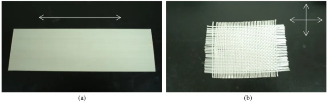
For the lamina for the production of the glulam, average moisture content of 12% was ensured and domestic larch ( Larix kaempferi Carr.) with an average specific gravity of 0.6 was used. As the reinforcement, textile glass fiber and sheet GFRP were used. The textile glass fiber was arranged in an overlapping plain with thick fiber bundles in warp and weft config- uration (Table 1). In the case of the sheet GFRP, it was formed from a combination of glass fiber and epoxy resin, and unlike the textile glass fi- ber, was arranged in a longitudinal direction, and the thickness of sheet GFRP was 1 mm (Fig. 1).
2.2. Production of Reinforced Glulam and Steel Plate Insertion Type Shear Specimen
The glulam and reinforced glulam were 5 ply, and the reinforcing material was inserted in
Reinforcement
Material Thickness
(mm)
Orientation of glass fiber
Tensile strength (MPa)
Main Adhesive
Sheet GFRP
E-Glass Fiber
Epoxy 1.0 Uni-directional 1633
Textile glass fiber - Warp : 0.25
Bi-directional -
Weft : 0.25
Table 1. Properties of glass fiber reinforcements
between the outermost lamina and inner lamina and plied (Fig. 2). In the case of the sheet GFRP reinforced glulam, a “GS” marking was
used, while for the textile glass fiber reinforced glulam, a “GT” marking was used. For the pro- duction of the GS glulam, the adhesive used was a vinyl acetate resin type adhesive of MPU500/HH60, while for the GT glulam, a resorcinol resin adhesive of Synteko1711/2623 was used. For the produced glulam, as shown in Fig. 2, in order to produce the steel plate insertion type shear specimen, bolt holes were located at 5D end distance (D = diameter of bolt) and at 7D which is the standard for design standards. In the middle of the glulam, a 10 mm slit was made to accommodate the insertion of a 8 mm steel plate. In accordance with the specimen types, 5 each, i.e., a total of 60 pieces of specimens were produced. The nomenclature of the specimens is presented in Table 2.
↔ Orientation of the glass fiber
(a) (b) Fig. 1. Materials of sheet GFRP (a) and textile glass fiber (b).
Fig. 2. Connection shape of reinforced glulam specimens.
(Note : “t” in depth is thickness of reinforcement ).
Fastener Bolt Diameter Reinforcement Abbreviation End-distance
Bolt 12 mm Non-reinforced CO
Sheet GFRP GS 5D*
16 mm textile glass fiber GT 7D
* “D” means the diameter of bolt
Table 2. Nomenclature of control and reinforced glulam connection specimens
2.3. Tensile Shear Testing Method
For the tensile type shear testing, steel plates were inserted into the shear specimen and were connected via 12 mm and 16 mm bolts.
Metallic devices were installed on the inserted steel plates, and by attaching 2 displacement transducers (50 mm capacity) on either side, the average values of measurements were used. As a fixture of specimens, two bolts with 20 mm diameter were used, and the bolt spacing and end distance fixture was 60 mm and 130 mm, respectively. Load and deformation were re- corded using a data logger (TDS302), and the loading speed was 10 mm/min.
3. RESULTS and DISCUSSION 3.1. Shear Strength of The Bolted
Connection of Reinforced Glulam
The average maximum shear strength of the control material of the 7D end distance for the 12 mm diameter bolted connection was 35.44 kN, and in the case in which the end distance was decreased to 5D, the average maximum shear strength was decreased by 13%. The aver- age maximum shear strength of the control specimen of the 7D end distance for the 16 mm diameter bolted connection was 59.12 kN, and for 5D, it was decreased by 23% compared to the average maximum shear strength of 7D. The average maximum shear strength, which is de- pendent on the increase in the bolt diameter of the same end distance, was increased by 39% in the case of 5D and by 58% in the case of 7D.
The load deformation curve of the 12 mm con- trol bolted connection displayed, after reaching the maximum shear strength, a better ductility than the 16 mm.
The maximum shear strength of the bolted connection of the 12 mm GS reinforced glulam with 7D end distance was 41.67 kN and it was decreased by 13% in the case in which the end distance was decreased to 5D, and with the max- imum strength of Control 7D as the basis, that of 7D of GS specimen was increased by 18%. The 16 mm bolted connection 7D was 67.33 kN, and it displayed a similar rate of decrease as the 12 mm when the end distance was decreased, and with the Control 7D specimen as the basis, it showed values that were increased by 20%. In accordance with the increases in the bolt diame- ter, the average maximum shear strength of the same end distance showed increases of 54% in the case of 5D, and of 62% in the case of 7D.
The load deformation curve of the bolted connection of the GS glulam showed a good ductility after the maximum shear strength at 12 mm, but at 16 mm, it was possible to ascertain that after the maximum shear strength was reached the load decreased momentarily.
For the bolted connection of the 12 mm GT
reinforced glulam, the maximum shear strength
of the 7D end distance was 57.94 kN, which
was similar for the 5D, and most of the max-
imum load of the GT specimen measured by
failure of bolt. With the Control 7D as the
basis, the average maximum shear strength of
GT glulam increased by 71% and 63% in the
cases of 5D and 7D, respectively. Fig. 3 shows
(a)
(b)
(c)
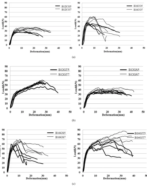
Fig. 3. Typical load-deformation curves of CO (a), GS (b) and GT (c) specimens using 12 mm (right) and 16
mm (left) bolt according to end distance 5D (bold line) and 7D (ordinary line).
that the shear strength of the GT specimens using 12 mm bolt displayed a modest stiffness past the proportional limit region until the maximum shear strength, and that as the bolt failed the shear strength decreased slowly, while displaying a good ductility. In the case of the 16 mm, the maximum shear strength of 7D was 78.29 kN, and it showed a decrease of 22% when it was decreased to 5D. The load deformation curve of the 16 mm showed the first phase shear strength, as the timber between the steel plate and the reinforcement broke;
however, afterwards, as the reinforcement inhibited the spreading of splitting fracture, it was possible to ascertain that the textile glass fiber and the outermost lamina that were still intact maintained the shear strength.
3.2. Failure Mode of the Bolted
Connection of Glass Fiber Reinforced Glulam
The failure behaviors from the current test were compared with the failure modes proposed by the EYM. It is reported that the failure mode of the bolted connection of larch glulam were mostly momentary splitting failures of the glulam (Masahiro et al., 2009).
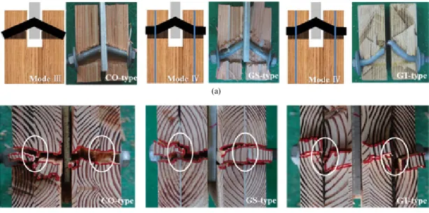
In the cases of the bolted connections of the 12 mm of the control glulam (CO5, CO7) and sheet GFRP reinforced glulam (GS5), the fail- ure phenomenon, as shown in Fig. 4, the center of the bolt bent due to tensile load, thereby em- bedding the glulam and the reinforced glulam and causing a shear splitting fracture, but the bolt did not fail (Mode Ⅲ). In the case of 7D end distance of the GS and the GT, the failure mode was such that the bolt yielded at the
(a)
(b)
Fig. 4. Failure mode by type of specimen (a-inner side, b-upper side).
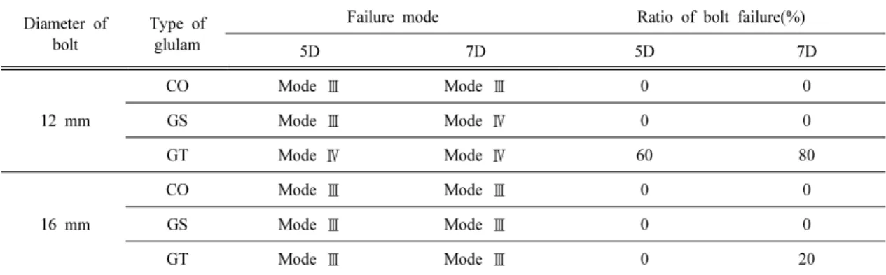
center of the bolt and the reinforced position (Mode Ⅳ). Table 3 shows the comparison of the failure mode and ratio of bolt failure by each type, and it indicates that the textile glass fiber reinforced glulam displayed a higher fail- ure ratio of the bolt than the control glulam and the sheet glass fiber reinforced glulam. The failure mode of the bolted connection of the 16 mm manifested, as a result of increases in the diameter, as the Mode Ⅲ, while in the case of the control glulam, the failure mode of mo- mentary splitting was observed. This was a similar trend to the results observed by Kim et al. (2008) where, in the performance evaluation of the connection shear strength of a steel plate insertion type drift pin of glulam, Mode IV was transformed into Mode III when the bolt diame- ter was increased from 6 mm to 12 mm. The failure mode of a single bolted connection shows that as the diameter increases, the plastic yield deformation is reduced, and as the diame- ter decreases, the failure mode of Mode IV is measured more than Mode Ⅲ. For the failure mode of a multi-row bolted connection, it is re-
ported that failure modes differ with different diameters, like a single bolted connection (Mastschuch, 2000). The GS specimen using 16 mm bolt showed a similar failure behavior to the 12 mm bolted specimens, although the primary failure mentioned in the load-deforma- tion curve occurred as a splitting failure in the lamina between the steel plate and the reinforcement. Because of the reinforcement and outermost lamina that were still intact, the load was maintained, and afterwards the com- plete failure of the specimen was observed.
Based on these findings, it was possible to as- certain that the reinforcing material had in- hibitory effects where the spreading of splitting is curbed from transitioning into the outermost lamination material. As seen in the case of Mode III show, the lower part of the washer was embedded due to the behavior of the bolt as the tensile load increased. As such, it is be- lieved that this failure can be complemented be augmented by augmentingation the washer.
Mode IV, in accordance with the configuration and thickness of the reinforcement, is expected
Diameter of bolt
Type of glulam
Failure mode Ratio of bolt failure(%)
5D 7D 5D 7D
12 mm
CO Mode Ⅲ Mode Ⅲ 0 0
GS Mode Ⅲ Mode Ⅳ 0 0
GT Mode Ⅳ Mode Ⅳ 60 80
16 mm
CO Mode Ⅲ Mode Ⅲ 0 0
GS Mode Ⅲ Mode Ⅲ 0 0
GT Mode Ⅲ Mode Ⅲ 0 20
Table 3. Failure mode and ratio of bolt failure in bolted connection
to undergo variations in the curvature of the bolt and the inhibitory effects on the spreading of splitting of the timber, and is expected to see increases in the reinforcing effects as well.
3.3. The 5% Yield Load of Bolted Connection
In the case of the bolted connection of 12 mm, the average yield shear strength of the 7D end distance of the control material was 25.62 kN, and the control 5D showed a decrease of 16% compared to 7D. When the bolt diameter is increased to 16 mm while the end distance is the same, it was possible to ascertain that the rates of increase for the average yield shear strength increased significantly, by 59% and by 41% for 5D and 7D, respectively. The average yield shear strength of the 7D of the GS glulam was increased by 12% with the CO specimen as the basis, while that of the 5D was increased by 16%. When the bolt diameter increased in the GS specimen, the rates of in- crease for the average yield shear strength were 1.54 and 1.62 for the 5D and 7D, respectively, showing similar values to the control specimen.
The yield strength of the 7D end distance with 12 mm of the GT glulam was 33.15 kN, which was a 29% increase from the control, and 5D showed an increase of about 26%. As the diam- eter increased, the GT specimen increased by 1.46 times and by 1.38 times in the cases of 5D and 7D, respectively. Through this, it is confirmed that the shear yield strength is im- proved when the bolted connection is reinforced
with glass fibers as compared to the bolted joint in the non-reinforced glulam. The failure mode of the 12 mm connection, more so than the embedment of the glulam due to the bolt, is a splitting failure in the glulam caused by the yielding of the bolt due to the applied tensile load. As such, in the case of the textile glass fiber reinforced glulam, it is thought that the glass fiber strands that are aligned in the di- rection perpendicular to the grain inhibit the yielding of the bolt, thus increasing the yield shear strength. The increase in the diameter is expected to exert a more significant effect as the metal fastener increases the of force that acts on the specimen on the shear failure due to embedment than on the splitting failure.
3.4. Coefficient Calculation of Location in Accordance with the Glulam Reinforcement
If the end distance is less than 7D, it is ad-
visable to reduce the yield shear strength by
multiplying the coefficient of location (C
5d) by
the standard yield strength. The yield shear
strength that is dependent on the reduction of
the end distance was, in accordance with the
timber structure design of Korean Building
Code (KBC, Architectural Institute of Korea,
2005), calculated using the minimum distance
(3.5D) for the standard allowed shear strength
when the end distance of the bolt is reduced,
and, in the case in which the minimum distance
(7D) for the total standard allowed shear
strength is the middle, the coefficient of loca-
tion (C
5d) was calculated using the following equation and was multiplied by the yield shear strength for the bolted connection.
C
5d= the coefficient of minimum end distance (7D) for the total allowable strength and the actual end distance (5D)
As such, the C
5dfor the 5D end distance of a single bolt connection that was applied to the test of this paper was 0.71. The coefficients of decrease that are dependent on the end distance of the reinforced glulam were compared.
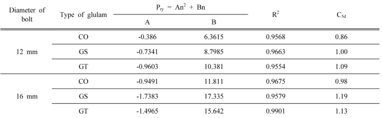
Through the correlation of the yield shear strength that is dependent on the 7D of the control material and the 5D of the reinforced glulam, the coefficients of decrease were calculated. For the coefficients of decrease, through the yield shear strength and the quad- ratic regression model of the end distance, the predicted yield shear strength was obtained as:
··· (1)
where,
P
ry= Predicted yield strength (N) in accord- ance with end distance
n = e/d
e = End distance (5D or 7D) d = Bolt diameter
b
1, b
2= Regression coefficients
Table 4 shows a comparison of the predicted yield shear strength (P
ry) obtained through a quadratic regression analysis and the yield shear strength (P
exp) obtained through an experiment.
It can be seen that in all types, the coefficients of determination are greater than 0.95 and are well matched. The coefficient of location for the 5D end distance (C
5d) was used to obtain, with the predicted yield shear strength of the control material of the 7D end distance as the basis, the strength ratio of the predicted yield shear strength of each type of the 5D end dis- tance with the same diameter. With the control material, the coefficients of location (C
5d) of 12 mm and 16 mm bolted connections were 0.86
Diameter of
bolt Type of glulam
P
ry= An
2+ Bn
R
2C
5dA B
12 mm
CO -0.386 6.3615 0.9568 0.86
GS -0.7341 8.7985 0.9663 1.00
GT -0.9603 10.381 0.9554 1.09
16 mm
CO -0.9491 11.811 0.9675 0.98
GS -1.7383 17.335 0.9579 1.19
GT -1.4965 15.642 0.9901 1.13
R2 = Coefficient of determination
C5d = Ratio of Pry (5D) to Pry (CO, 7D) at the same diameter of a bolt