Cone-beam computed tomography-guided three-dimensional evaluation of treatment effectiveness of the Frog appliance
9
0
0
전체 글
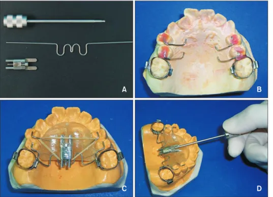
(2) Li et al • Evaluate the Frog appliance by CBCT. INTRODUCTION Class II relationship accompanied by crowding is a common malocclusion seen in clinics. Typically, orthodontists must choose between tooth extraction or nonextraction when treating this type of malocclusion. Alexander1 and Alexander2 suggested avoiding tooth extraction because non-extraction can maintain the physiological status of the stomatognathic system, shorten the treatment course, and help obtain superior occlusion. In recent years, orthodontists have increasingly favored non-extraction therapy in cases with mild-tomoderate crowding, after comprehensively considering the relationships among the teeth, jaw, and face. However, many methods exist to solve mild or moderate crowding without tooth extraction, including interproximal enamel stripping, arch expansion, and molar distalization. The gap produced through interproximal enamel stripping is limited, but this might damage the enamel and lead to a high risk of tooth caries. The results of arch expansion are greatly influenced by the age of the patient, and final occlusion is not sufficiently stable and may cause a relapse. Molar distalization has become increasingly popular due to the fact that the molar relationships are adjusted, a certain amount of space is achieved and pain from tooth extractions can be avoided. Various kinds of appliances can be used to distalize the molars clinically, such as face-bows, pendulum appliances, and implants. With advances in materials and technology, the Frog molar distalization appliance was. developed and became accepted because it does not rely on patient cooperation, is comfortable, is easily manipulated, and causes less trauma.3 Although some studies have used two-dimensional radiographs to evaluate the efficiency of the Frog appliance in the sagittal and vertical dimensions, few have evaluated transverse changes by using study models.4-12 Two-dimensional radiographs have some limitations, including magnification, geometric distortion, superimposed structures, and inconsistency of head position.13,14 When considering transverse changes, measurements based on study models focus only on the crown, whereas changes of the root in the bones are neglected. Cone-beam computed tomography (CBCT) can illustrate the responses of the teeth to maxillary molar distalization more accurately than two-dimensional radiography, and could provide more information compared to study models. First, CBCT images display structures accurately and precisely without magnification or distortion, and can eliminate the superimposition of symmetrical structures.13 Second, they help visualize the roots from all possible directions, which is superior to what can be visualized using conventional two-dimensional radiographs and study models.13-15 Several studies have reported the effects of the eruption of the maxillary second molars on molar distalization, but the results have been controversial. Some have reported limited effects, whereas others have reported significant effects.16-19 Therefore, the aim of this study was to evaluate the treatment effect of the Frog appliance in patients with-. Figure 1. Structure of the Frog appliance (FORESTADENT Bernhard Förster GmbH, Pfor zheim, Germany). A, Compo nents of the Frog appliance, from top to bottom: screwdriver, preformed spring, and screw. B, Occlusal rest, one of the anchorage devices in the appliance. C, Fabrication of the complete appliance, each part of which is connected by an elastic band and Nance button. D, Activation of the appliance. 162. https://doi.org/10.4041/kjod.2019.49.3.161. www.e-kjo.org.
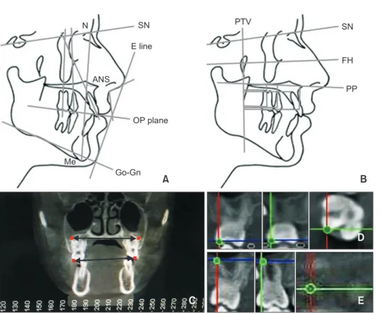
(3) Li et al • Evaluate the Frog appliance by CBCT. out erupted maxillary second molars. Measurements were performed using three-dimensional CBCT, which allowed the assessment of root movements during molar distalization, particularly in the transverse dimension.. MATERIALS AND METHODS The protocol of this study was reviewed and improved by the Stomatological Hospital of Xi’an Jiaotong Univer-. sity. Samples The power analysis showed that a sample size of 19 per group will yield a significant (p < 0.05) result 90% of the time. We expanded the sample size in case of accidental withdrawal. Thus, 40 patients (21 boys and 19 girls), aged 10 to 13 years (average, 11.7 years), were included in this study. All patients had Angle Class II di-. Figure 2. Intraoral view after treatment.. Figure 3. Cephalometric measurements performed in the study. A, B, Linear and angular measurements. C, Coronal measurements of the maxillary first molars. The upper two red dots indicate bilateral distobuccal root apices of the maxillary first molars; the lower two red dots indicate bilateral distobuccal cusps of the maxillary first molar. D, E, Position of the distobuccal cusp (D) and distobuccal root apex (E) of the right maxillary first molars in the coronal (left), sagittal (middle), and transverse (right) directions. N, Nasion; SN, sella-nasion; E line, esthetic plane; ANS, anterior nasal spine; OP, occlusion plane; Me, menton; Go-Gn, mandibular plane; PTV, pterygoid vertical; FH, Frankfort horizontal plane; PP, palatal plane. www.e-kjo.org. https://doi.org/10.4041/kjod.2019.49.3.161. 163.
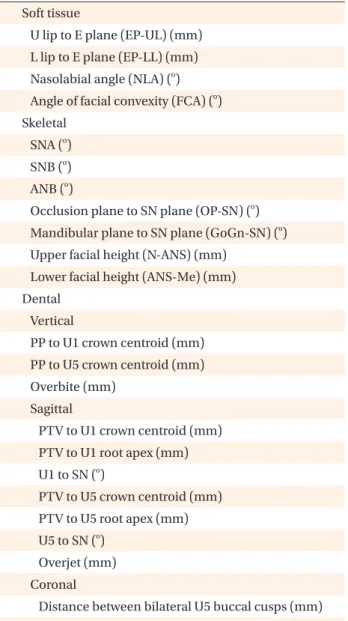
(4) Li et al • Evaluate the Frog appliance by CBCT. vision 1 malocclusion and an A point - Nasion - B point angle (ANB) of 0 to 4o, with mild or moderate crowding (0 to 5 mm) in the upper arch, whereas the lower arch had mild or no crowding. They had either late mixed deciduous dentition or early permanent dentition, average or hypo-divergent vertical facial type, and no erupted second premolars. The study protocol was approved by the Institutional Review Board of Stomatological Hospital of Xi’an Jiaotong University (IRB approval no. [2018]015). Treatment The patients all received a two-step treatment: removable appliance and conventional fixed appliance treatment. The patients first had to wear the Frog appliance (FORESTADENT Bernhard Förster GmbH, Pforzheim, Germany) (Figure 1), which comprised a screw, a 0.032mm wire with a preformed spring, and a screwdriver. The fabrication of this appliance involved a combination of the aforementioned components, according to each patient’s model. First, appropriate bands with lingual sheaths were chosen for the maxillary first molars, followed by placement of the screw according to the following points: (1) the axis of the screw should be in accordance with the palatal midline; (2) the screw should be parallel to the occlusal plane or the distal end should be slightly towards the palate, with the distal edge of the screw and the mesial edge of the lingual sheath in alignment; and (3) the Frog screw should be placed as close to the level of the center of resistance of the molars as possible, which is typically 10 to 12 mm below the occlusal plane. Subsequently, occlusal rests were bent and placed on the maxillary first and second premolars, and a Nance arch was then made to reinforce. the anchorage. Finally, the 0.032-mm wire was bent with another bilateral loop, which was inserted into the lingual sheath bent by approximately 15o towards the occlusal plane to avoid distal tipping of the molar. When wearing the Frog appliance, the patients needed to rotate the screwdriver 720o counterclockwise every 2 weeks, causing 0.8-mm distalization of the Frog appli-. Table 2. Cephalometric variables for the soft tissues, skeletal tissues, and anchorage teeth Soft tissue U lip to E plane (EP-UL) (mm) L lip to E plane (EP-LL) (mm) Nasolabial angle (NLA) (o) Angle of facial convexity (FCA) (o) Skeletal SNA (o) SNB (o) ANB (o) Occlusion plane to SN plane (OP-SN) (o) Mandibular plane to SN plane (GoGn-SN) (o) Upper facial height (N-ANS) (mm) Lower facial height (ANS-Me) (mm) Dental Vertical PP to U1 crown centroid (mm) PP to U5 crown centroid (mm) Overbite (mm) Sagittal PTV to U1 crown centroid (mm). Table 1. Cephalometric variables for the maxillary first molar Vertical PP to U6 crown centroid (mm) Sagittal PTV to U6 crown centroid (mm) PTV to midpoint between U6 mesiobuccal and distobuccal root apices (PTV-U6a) (mm) U6 to sella-nasion (o) Coronal Distance between bilateral U6 mesiobuccal cusps (mm) Distance between bilateral U6 distobuccal cusps (mm) Distance between bilateral U6 mesiobuccal root apices (mm) Distance between bilateral U6 distobuccal root apices (mm) PP, Palatal plane; U6, maxillary first molar; PTV, pterygoid vertical.. 164. PTV to U1 root apex (mm) U1 to SN (o) PTV to U5 crown centroid (mm) PTV to U5 root apex (mm) U5 to SN (o) Overjet (mm) Coronal Distance between bilateral U5 buccal cusps (mm) Distance between bilateral U5 root apices (mm) U lip, Upper lip; E plane, esthetic plane; L lip, lower lip; FCA, the angle between the line connecting glabella to subnasale and the line connecting subnasale to soft-tissue pogonion; SNA, sella-nasion-A point; SNB, sella-nasion-B point; ANB, A point-nasion-B point; SN, sella-nasion; N, nasion; ANS, anterior nasal spine; Me, menton; PP, palatal plane; U1, maxillary central incisor; U5, maxillary second premolar; PTV, pterygoid vertical.. https://doi.org/10.4041/kjod.2019.49.3.161. www.e-kjo.org.
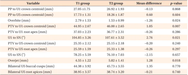
(5) Li et al • Evaluate the Frog appliance by CBCT. ance. Follow-up visits were scheduled to examine the retention of the appliance, the movement of the molars, and the occlusal relationship. The first molars achieving a neutral or distal occlusal relationship signaled the end of the first stage of treatment (Figure 2). The occlusal rests on the second and first premolars were removed individually during the aligning, leveling, and retraction stages, whereas the screw was replaced with a trans-palatal arch to maintain the treatment effect and reinforce the anchorage. Evaluation To evaluate the treatment effects of the Frog appliance, CBCT (PaX-Zenith3D; VATECH, Hwaseong, Korea). was performed both before treatment (T1) and at the end of phase 1 (T2) for each patient. The images were then uploaded to software (version 11.8; Dolphin Imaging and Management Solutions, Chatsworth, CA, USA), and two lateral cephalometric radiographs were obtained for further cephalometric analysis on the right and left sides, by using three-dimensional reconstructed CBCT images. The measurements for the sagittal and vertical variables were determined using the cephalometric radiographs, while the coronal variables were determined directly by using the CBCT images (Figure 3). The details of the variables are listed in Tables 1 and 2. The measurements were performed twice by one investigator, with an interval of 2 weeks. For each sample, we used. Table 3. Comparison of the maxillary first molar induced by Frog appliance before (T1) and after (T2) treatment Variable. p -value. T1 group. T2 group. Mean difference. PP to U6 crown centroid (mm). 17.03 ± 2.28. 16.96 ± 2.15. −0.07. 0.630. PTV to U6 crown centroid (mm). 17.89 ± 1.65. 13.65 ± 1.75. −4.25. < 0.001. PTV to midpoint between U6 mesiobuccal and distobuccal root apices (PTV-U6a) (mm). 17.45 ± 2.33. 13.92 ± 2.04. −3.53. 0.035. U6 to SN (o). 60.08 ± 4.76. 62.33 ± 4.82. 2.25. 0.111. Bilateral U6 mesiobuccal cusps (mm). 49.01 ± 1.80. 49.85 ± 1.95. 0.84. 0.046. Bilateral U6 distobuccal cusps (mm). 51.94 ± 2.00. 54.81 ± 2.34. 2.87. 0.007. Bilateral U6 mesiobuccal root apices (mm). 45.99 ± 2.78. 47.04 ± 2.47. 1.05. 0.051. Bilateral U6 distobuccal root apices (mm). 49.65 ± 2.71. 49.24 ± 3.31. −0.41. 0.510. Values are presented as mean ± standard deviation. See Tables 1 and 2 for abbreviations and definitions of each landmark or measurement. Paired-samples t -test was used; statistically significant at p < 0.05.. Table 4. Comparison of anchorage teeth induced Frog appliance before (T1) and after (T2) treatment T1 group. T2 group. Mean difference. p -value. PP to U1 crown centroid (mm). 27.05 ±1.75. 26.92 ± 1.93. −0.13. 0.868. PP to U5 crown centroid (mm). 17.73 ± 1.31. 18.26 ± 1.87. 0.60. 0.604. Variable. 2.79 ± 1.53. 1.53 ± 0.99. −1.26. 0.024. PTV to U1 crown centroid (mm). Overbite (mm). 44.95 ± 2.67. 46.00 ± 2.65. 1.05. 0.007. PTV to U1 root apex (mm). 37.03 ± 2.23. 36.77 ± 2.31. −0.26. 0.286. o. U1 to SN ( ). 104.85 ± 3.26. 107.61 ± 3.52. 2.76. 0.021. PTV to U5 crown centroid (mm). 25.35 ± 2.12. 25.15 ± 2.18. −0.20. 0.240. PTV to U5 root apex (mm). 25.59 ± 1.59. 25.33 ± 1.38. −0.26. 0.297. 78.25 ± 5.59. 76.10 ± 7.03. −2.15. 0.657. 4.55 ± 1.22. 5.82 ± 1.41. 1.28. 0.018. Bilateral U5 buccal cusps (mm). 44.38 ± 3.92. 45.73 ± 3.55. 1.35. 0.770. Bilateral U5 root apices (mm). 38.95 ± 3.57. 38.74 ± 3.20. −0.21. 0.740. o. U5 to SN ( ) Overjet (mm). Values are presented as mean ± standard deviation. See Tables 1 and 2 for abbreviations and definitions of each landmark or measurement. Paired-samples t -test was used; statistically significant at p < 0.05.. www.e-kjo.org. https://doi.org/10.4041/kjod.2019.49.3.161. 165.
(6) Li et al • Evaluate the Frog appliance by CBCT. Table 5. Comparison of changes in the soft and skeletal tissues induced by Frog appliance before (T1) and after (T2) treatment Variable. T1 group. T2 group. Mean difference. p -value. EP-UL (mm). 1.83 ± 0.74. 1.31 ± 0.75. −0.52. 0.010. EP-LL (mm). 2.73 ± 0.45. 2.43 ± 0.27. −0.29. 0.196. o. 98.71 ± 8.26. 96.35 ± 8.72. −2.38. 0.279. o. FCA ( ). 13.57 ± 2.62. 13.94 ± 2.79. 0.38. 0.419. SNA (o). 80.55 ± 2.55. 81.07 ± 2.01. 0.52. 0.458. 77.63 ± 2.48. 77.73 ± 2.35. 0.10. 0.865. NLA ( ). o. SNB ( ) o. ANB ( ). 2.92 ± 1.18. 3.38 ± 1.24. 0.47. 0.205. 20.11 ± 2.83. 21.09 ± 3.28. 0.98. 0.535. GoGn-SN ( ). 34.16 ± 3.68. 34.46 ± 2.45. 0.29. 0.719. N-ANS (mm). 54.61 ± 4.26. 54.76 ± 4.35. 0.43. 0.595. ANS-Me (mm). 62.83 ± 2.98. 63.44 ± 2.95. 0.63. 0.394. OP-SN (o) o. Values are presented as mean ± standard deviation. See Tables 1 and 2 for abbreviations and definitions of each landmark or measurement. Paired-samples t -test was used; statistically significant at p < 0.05.. the average value of the right and left lateral cephalometric radiographs for each variable, except for the coronal variables, as the final results. Statistical analysis The intrareliability of the principal investigator was tested by measuring all of the samples as described previously, with measurements repeated 2 weeks later. The measurements showed high reliability (r > 0.9). The data analysis was performed using the paired-samples t -test. Because the raw data for a few variables were not distributed on a normal curve, as indicated by the Shapiro– Wilk normality test, we performed nonparametric tests. Since similar results were found with the parametric and nonparametric tests, the parametric data were reported for all variables. Statistical significance was set at 0.05. Data analysis was performed using PASW Statistics for Windows, version 18.0 (IBM Corp., Armonk, NY, USA).. RESULTS The paired-samples t -test was used to compare the mean difference between T1 and T2 for each variable. Eight variables reflected the changes in the maxillary first molars. Among them, the distance from the crown centroid of the maxillary first molar to the pterygoid vertical (PTV) plane decreased by 4.25 mm (p < 0.001). The distance from the midpoint of the maxillary first molar’s mesiobuccal and distobuccal root apices to the PTV plane decreased by 3.53 mm (p < 0.05), while the angle of the maxillary first molar’s long axis to the sella-nasion (SN) plane increased by 2.25o, which indicated that the teeth had tipped toward the distal end.. 166. Compared to these sagittal measurements, the vertical dimension showed no significant change. While the distance between the bilateral mesiobuccal cusps and the distance between the bilateral distobuccal cusps increased by 0.84 mm (p < 0.05) and 2.87 mm (p < 0.01), respectively, no significant changes were observed in the transverse width between the bilateral root apices (Table 3). Regarding the measurements of the anchorage teeth, 12 variables representing the three-dimensional changes were measured. The changes in the maxillary second premolar were not significant, whereas the distance from the crown centroid of the maxillary central incisor to the PTV plane increased significantly by 1.05 mm (p < 0.05), and the angle of the long axis to the SN plane increased by 2.76o (p < 0.05). Furthermore, compared to the pretreatment stage, after treatment, overjet increased (p < 0.05) and overbite decreased (p < 0.05) (Table 4). Among these changes in the soft tissues, only the distance from the upper lip to the esthetic plane decreased significantly, by 0.52 mm (p = 0.01). This may be attributable to the proclination of the maxillary central incisor. Interestingly, none of the seven variables related to the skeletal tissues differed significantly between T1 and T2 (Table 5).. DISCUSSION Although some studies have verified the Frog appliance as being effective,11,12,20,21 the cephalometric radiographs used were two-dimensional representations of three-dimensional structures. This can lead to errors in identification, and the aforementioned studies paid little attention to root movement during distalization. Thus,. https://doi.org/10.4041/kjod.2019.49.3.161. www.e-kjo.org.
(7) Li et al • Evaluate the Frog appliance by CBCT. in this study, we evaluated three-dimensional CBCT images and assessed root movements, particularly in the transverse dimension, for the first time. Regarding the controversy over the effects of the maxillary second molars on distalization,16,22-24 the influence cannot be completely excluded. Hence, this study included patients whose maxillary second molars had not yet erupted. In our study, in the sagittal view, the Frog appliance significantly distalized the maxillary molars by an average of 4.25 mm. The displacement was slightly smaller than that reported by Burhan (5.51 mm),20 and the amount of tipping per millimeter of sagittal movement (0.53o) was significantly less than that reported by Burhan (0.90o).20 This may have resulted from the different inclusion criteria of the two studies; the patients in Burhan’s study20 all had fully erupted maxillary second molars. Kinzinger et al.16,23 and Byloff et al.25 reported that the eruption of the maxillary second molars contributes to significant molar tipping. Several methods can be used to reduce unwanted tipping. The force point should be changed according to the position of the second molars. In this study, the Frog screw was placed as close to the level of the center of resistance of the molars as possible, which is typically located 10 to 12 mm below the occlusal plane, but if the maxillary second molar has erupted, the distance should be reduced to 9 to 10 mm. Furthermore, the double-bend in our study was bent by approximately 15o towards the occlusal plane to partially avoid tipping during distalization. This adjustment has been used for a pendulum appliance, with favorable results.25-27 In addition, Burhan20 reported that the amount of molar tipping per millimeter of sagittal movement can be reduced (0.21o) using high-pull gear, which also increases molar distalization (5.93 mm). Furthermore, Nienkemper et al.28 reported that the molars can move bodily to the distal end without tipping with the help of mini-implants. From the vertical view, the molars showed slight extrusion (0.07 mm). The strict control over the vertical movement of the molars in our study might have been due to the well-positioned double-bend, which was at the same level as the band sheath; a position that is too low leads to intrusion, and a position that is too high leads to extrusion. A literature review revealed that most evaluations of transverse change have been based on study models or the superimposition of photocopies of plaster models, and that they have focused primarily on crown movement,9-12 with little attention paid to root movement. In the present study, transverse change was evaluated in both the roots and crowns by using CBCT images. The distance between the bilateral mesiobuccal and distobuccal cusps increased significantly by 0.84 mm. www.e-kjo.org. https://doi.org/10.4041/kjod.2019.49.3.161. and 2.87 mm, respectively. This indicated distobuccal rotation of the molar, which supported the findings of Uzuner et al.12 Regarding the root, the results showed that the distance between the bilateral mesiobuccal root apices increased by 1.05 mm, and the distance between the bilateral distobuccal root apices decreased by 0.41 mm, but these changes were small and nonsignificant. Combining all of these changes in the transverse dimension, we noticed buccal crown torque during distalization. Distobuccal rotation and buccal crown torque during treatment with the Frog appliance could not be completely avoided because the force point is relatively far from the axis of the molars. Theoretically, toe-in and lingual crown torque achieved using a wire inserted into the lingual sheath can act as a preventive measure. However, this creates a complex multi-couple system, making accurate control and balance of strength highly difficult. The side effect of mesiobuccal rotation can also occur,16 and implementing this system is difficult in practice. The loss of anchorage is another concerning aspect of molar distalization. In our study, U1-SN (o) and U1PTV (mm) showed acceptable increases of 2.76o and 1.05 mm, respectively, which indicated anchorage loss in the anterior teeth. Other studies have reported similar results of the flaring of the maxillary incisors and have shown that the use of the Frog appliance combined with highpull gear has reduced the extent of flaring.20,21 A systematic review by Fudalej and Antoszewska29 suggested that the use of temporary skeletal anchorage devices could help avoid labial movement of the maxillary incisors during molar distalization. Based on the design of the Frog appliance, force was mainly applied to the maxillary first molars and the anchorage parts, including the palate and premolars, to avoid major changes in the skeletal tissue. Moreover, the treatment duration was only 4.5 months on average, which was too short to influence the growth of bones.. CONCLUSION The Frog appliance is a fixed intraoral device that can effectively distalize the maxillary molars in patients with Class II division 1 malocclusion whose maxillary second molars have not yet erupted. The appliance also allows distalization of the molars with an acceptable degree of tipping, distobuccal rotation, and buccal crown torque. Less anchorage loss in the study can be achieved only if the appliance is properly fabricated, and this requires the screw to be well-positioned at 10 to 12 mm lower than the occlusal plane as well as the addition of a 15o bend towards the occlusal plane end of the preformed wire. Furthermore, CBCT images can display three-dimensional structures accurately and precisely, making three-. 167.
(8) Li et al • Evaluate the Frog appliance by CBCT. dimensional analysis simple and reliable, suggesting its wide applicability in future clinical research.. CONFLICTS OF INTEREST No potential conflict of interest relevant to this article was reported.. ACKNOWLEDGEMENTS This study was supported by the grant from Health Research Project of Shaanxi Province (2014D58), grant from Key Technological Project of Shaanxi Province (2015SF156), and the Nature Science Foundation of China (Grant 81600912).. REFERENCES 1. Alexander SA. Diagnosis and treatment planning in orthodontics. Curr Opin Dent 1992;2:9-13. 2. Alexander RG. The vari-simplex discipline. Part 2. Nonextraction treatment. J Clin Orthod 1983;17: 474-82. 3. Ludwig B, Glasl B, Kinzinger GS, Walde KC, Lisson JA. The skeletal frog appliance for maxillary molar distalization. J Clin Orthod 2011;45:77-84; quiz 91. 4. Byloff FK, Darendeliler MA. Distal molar movement using the pendulum appliance. Part 1: clinical and radiological evaluation. Angle Orthod 1997;67:24960. 5. Bondemark L, Kurol J. Distalization of maxillary first and second molars simultaneously with repelling magnets. Eur J Orthod 1992;14:264-72. 6. Escobar SA, Tellez PA, Moncada CA, Villegas CA, Latorre CM, Oberti G. Distalization of maxillary molars with the bone-supported pendulum: a clinical study. Am J Orthod Dentofacial Orthop 2007;131:545-9. 7. Chiu PP, McNamara JA Jr, Franchi L. A comparison of two intraoral molar distalization appliances: distal jet versus pendulum. Am J Orthod Dentofacial Orthop 2005;128:353-65. 8. Mavropoulos A, Karamouzos A, Kiliaridis S, Papadopoulos MA. Efficiency of noncompliance simultaneous first and second upper molar distalization: a three-dimensional tooth movement analysis. Angle Orthod 2005;75:532-9. 9. Nalcaci R, Kocoglu-Altan AB, Bicakci AA, Ozturk F, Babacan H. A reliable method for evaluating upper molar distalization: superimposition of three-dimensional digital models. Korean J Orthod 2015;45:828. 10. Duran GS, Görgülü S, Dindaroğlu F. Three-dimensional analysis of tooth movements after palatal. 168. miniscrew-supported molar distalization. Am J Orthod Dentofacial Orthop 2016;150:188-97. 11. Hourfar J, Ludwig B, Kanavakis G. An active, skeletally anchored transpalatal appliance for derotation, distalization and vertical control of maxillary first molars. J Orthod 2014;41 Suppl 1:S24-32. 12. Uzuner FD, Kaygisiz E, Unver F, Tortop T. Comparison of transverse dental changes induced by the palatally applied Frog appliance and buccally applied Karad's integrated distalizing system. Korean J Orthod 2016;46:96-103. 13. Kapila SD, Nervina JM. CBCT in orthodontics: assessment of treatment outcomes and indications for its use. Dentomaxillofac Radiol 2015;44:20140282. 14. Özalp Ö, Tezerişener HA, Kocabalkan B, Büyükkaplan UŞ, Özarslan MM, Şimşek Kaya G, et al. Comparing the precision of panoramic radiography and cone-beam computed tomography in avoiding anatomical structures critical to dental implant surgery: a retrospective study. Imaging Sci Dent 2018;48:269-75. 15. Jacobs R, Quirynen M. Dental cone beam computed tomography: justification for use in planning oral implant placement. Periodontol 2000 2014;66:20313. 16. Kinzinger GS, Fritz UB, Sander FG, Diedrich PR. Efficiency of a pendulum appliance for molar distalization related to second and third molar eruption stage. Am J Orthod Dentofacial Orthop 2004;125:823. 17. Flores-Mir C, McGrath L, Heo G, Major PW. Efficiency of molar distalization associated with second and third molar eruption stage. Angle Orthod 2013;83:735-42. 18. Joseph AA, Butchart CJ. An evaluation of the pendulum distalizing appliance. Semin Orthod 2000;6:129-35. 19. Kang JM, Park JH, Bayome M, Oh M, Park CO, Kook YA, et al. A three-dimensional finite element analysis of molar distalization with a palatal plate, pendulum, and headgear according to molar eruption stage. Korean J Orthod 2016;46:290-300. 20. Burhan AS. Combined treatment with headgear and the Frog appliance for maxillary molar distalization: a randomized controlled trial. Korean J Orthod 2013;43:101-9. 21. Bayram M, Nur M, Kilkis D. The frog appliance for upper molar distalization: a case report. Korean J Orthod 2010;40:50-60. 22. Kinzinger G, Syrée C, Fritz U, Diedrich P. Molar distalization with different pendulum appliances: in vitro registration of orthodontic forces and moments in the initial phase. J Orofac Orthop 2004;65:389409.. https://doi.org/10.4041/kjod.2019.49.3.161. www.e-kjo.org.
(9) Li et al • Evaluate the Frog appliance by CBCT. 23. Kinzinger GS, Wehrbein H, Diedrich PR. Molar distalization with a modified pendulum appliance--in vitro analysis of the force systems and in vivo study in children and adolescents. Angle Orthod 2005;75:55867. 24. Karlsson I, Bondemark L. Intraoral maxillary molar distalization. Angle Orthod 2006;76:923-9. 25. Byloff FK, Darendeliler MA, Clar E, Darendeliler A. Distal molar movement using the pendulum appliance. Part 2: the effects of maxillary molar root uprighting bends. Angle Orthod 1997;67:261-70. 26. Chaqués-Asensi J, Kalra V. Effects of the pendulum appliance on the dentofacial complex. J Clin Orthod 2001;35:254-7.. www.e-kjo.org. https://doi.org/10.4041/kjod.2019.49.3.161. 27. Bussick TJ, McNamara JA Jr. Dentoalveolar and skeletal changes associated with the pendulum appliance. Am J Orthod Dentofacial Orthop 2000;117:333-43. 28. Nienkemper M, Wilmes B, Pauls A, Yamaguchi S, Ludwig B, Drescher D. Treatment efficiency of mini-implant-borne distalization depending on age and second-molar eruption. J Orofac Orthop 2014;75:118-32. 29. Fudalej P, Antoszewska J. Are orthodontic distalizers reinforced with the temporary skeletal anchorage devices effective? Am J Orthod Dentofacial Orthop 2011;139:722-9.. 169.
(10)
수치
관련 문서
Correlation between root surface area measurements ob- tained using 3-dimensional (3D) laser scanning and cone-beam computed tomography (CBCT).. of Dentistry, Chiang Mai
CBCT를 이용하여 IGRT 시 치료 전 매일 CBCT를 시행하 여 set-up 오차를 검증하고 보정한다면 이를 통해 set-up 오 차를 줄일 수 있는 장점이 있지만 CBCT를 매일
Warford 등 13) 은 견치 교두정의 근원심적 위치가 매복을 예측 하는데 있어 가장 중요한 요소라고 하였다. 본 연구에서 근원심 적 위치 중 가장 많이 분포된 것으로
Purpose:The aim of the present study was to evaluate the incidence of the second mesiobuccal (MB2) canal, root fusion, and C-shaped root canal configuration in the Korean
the three types, the fusion of distobuccal and palatal root is the most common type. In other studies about root and canal morphology of maxillary molars, only 2 out of 83
Objective: To evaluate the mandibular buccal shelf (MBS) in terms of the angulation and bone depth and thickness according to sex, age, and sagittal and vertical skeletal patterns
The method of superimposition on the cranial fossa can help assess maxillary positional and remodeling changes relative to those of the anterior cranial fossa.14 The method
Patients with lingual-inclined incisors have lower ABT values at the root apex of the maxillary central incisor than patients with normal and labial-inclined incisors, and
