Kor. J. Mater. Res.
Vol. 20, No. 8 (2010)
429
†Corresponding author
E-Mail : [email protected] (W. -C. Oh)
Characterization of Co-AC/TiO
2Composites and Their Photonic Decomposition for Organic Dyes
Ming-Liang Chen, Joo-Hee Son, Chong-Yun Park, Yong-Chan Shin, Hyun-Woo Oh and Won-Chun Oh
†Department of Advanced Materials & Science Engineering, Hanseo University, Chungnam 356-706, Korea (Received July 10, 2010 : Received in revised form August 4, 2010 : Accepted August 5, 2010)
Abstract
In this study, activated carbon (AC) as a carbon source was modified with different concentrations of cobalt chloride (CoCl2) to prepare a Co-AC composite, and it was used for the preparation of Co-AC/TiO2 composites with titanium oxysulfate (TOS) as the titanium precursor. The physicochemical properties of the prepared Co-AC/TiO2 composites were characterized by N2 adsorption at 77 K, X-ray diffraction (XRD), scanning electron microscopy (SEM), and energy dispersive X-ray (EDX) analysis. The photocatalytic treatments of organic dyes were examined under an irradiation of visible light with different irradiation times. N2 adsorption data showed that the composites had decreased surface area compared with the pristine AC, which was 389 m2/g. From the XRD results, the Co-AC/TiO2 composites contained a mixturephase structuresof anatase and rutile, but a cobalt oxide phase was not detected in the XRD pattern. The EDX results of the Co-AC/TiO2 composites confirmed the presence of various elements, namely, C, O, Ti, and Co. Subsequently, the decomposition of methylene orange (MO, C14H14N3NaO3S) and rhodamine B (Rh.B, C28H31ClN2O3) in an aqueous solution, respectively, showed the combined effects of an adsorption effect by AC and the photo degradation effect by TiO2. Especially, the Co particles in the Co-AC/TiO2 composites could enhance the photo degradation behaviors of TiO2 under visible light.Key words
activated carbon, Titanium oxysulfate, Cobalt, XRD, photodegradation, visible light.1. Introduction
Colored wastewater is released in textile effluents and poses a potential environmental hazard. Within the eco- system, this colored wastewater is a dramatic source of pollution, eutrophication, and perturbations in aquatic life.
Moreover, a variety of organic chemicals are produced during the dyeing process, and some have been shown to be carcinogenic.
1)With the growing awareness of decreasing available water resources, many methods, including phys- ical, chemical, and biological methods, are being used in wastewater treatment and recycling. Among them, heteroge- neous photocatalysis appears to be an emerging destructive technology leading to the total mineralization of most organic pollutants.
2-6)TiO
2is the most widely used pho- tocatalyst because of its good activity, chemical stability, commercial availability, and inexpensiveness. Anatase has higher photocatalytic activity and has been studied more than the other two forms of TiO
2.
7)However, titania can operate only under UV light irradiation, since the light energy must be higher than its wide band gap (3.2 eV).
Currently many research efforts were aimed at the discovery of photocatalysts that work under visible light irradiation.
8)One such effort involved the usage of transition metal.
The presence of metal ion dopants in the TiO
2significantly influenced photoreactivity by changing charge carrier re- combination rates, and interfacial electron-transfer rates by shifting the band gap of the catalysts into the visible region.
9)Among the lots of transition metals, the band gap of Cr
2O
3(3.5 eV) is rather close to that of TiO
2. Anpo et al. substituted Cr
3+at lattice Ti
4+in TiO
2by ion-implantation method, and showed that the absorption band of Cr
3+- doped TiO
2shifted to the visible-light region.
10)Several attempts have been adopted to enhance the photocatalytic performance of TiO
2, such as immobilization of TiO
2powder onto supports like activated carbon fiber (ACF)
11)and activated carbon (AC).
12-16)AC is highly adsorptive owing to its developed pore structure and high specific area; moreover the particle size of commercial AC is usually in the micro-scale range. AC must be of medium surface area and porosity, to facilitate the diffusion of pollutants and release of products from the surface, and so many authors have reported a synergistic effect for AC- supported TiO
2systems,
12-16)such a high photocatalytic activity, photosensitivity and high adsorptive ability.
In this study, activated carbon (AC) was treated by
different concentration of cobalt chloride (CoCl
2) to prepare
Co-AC, and then reacted with titanium oxysulfate (TOS,
TiOSO
4) which as titanium precursor to prepare Co-AC/
TiO
2composites. X-ray diffraction was used to determine crystallinity. Scanning electron microscopy (SEM) was used to elucidate the mixing phenomenon and the size of Co-AC/TiO
2composites. Energy dispersive X-ray (EDX) analysis was used to analyze the elements and their content in Co-AC/TiO
2composites and a spectrophotometry was used to determine the decolorization of methylene orange (MO, C
14H
14N
3NaO
3S) and rhodamine B (Rh.B, C
28H
31-ClN
2O
3) solution which irradiation under visible light by different time.
2. Experimental Procedure 2.1 Materials
A porous and granular AC used in this study was pre- pared from coconut. The coconut shell was pre-carbonized first at 773 K, and then activated by steam diluted with nitrogen in a cylindrical quartz tube at 1023 K for 30 minutes. The AC was washed with deionized water and dried overnight in a vacuum drier at over 683 K. The CoCl
2used to modify the AC was obtained from Duksan Pure Chemical Co., Ltd, Korea. Titanium oxysulfate (TOS) as a titanium precursor was purchased from Sigma- Aldrich. Sulphuric acid (H
2SO
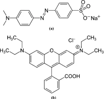
4, 95%) used to dissolve the TOS was purchased from Samchun Pure Chemical Co., Ltd, Korea. MO and Rh.B were selected as analytical grade which were purchased from Duksan Pure Chemical Co., Ltd, Korea. The molecular structures of MO and Rh.B are shown in Fig. 1.
2.2 Preparation of Co-AC/TiO
2composites
5 g of AC were added to 100 ml of different concen-
trations of CoCl
2: 0.05, 0.1 and 0.5 mol/L, respectively.
Then the mixture was stirred for 1h, clarified and poured out of the distilled water. The sediments of Co-AC were dried naturally at 373 K. On the other hand, 0.7 g TOS was dissolved in 100 mL of 0.1 mol/L H
2SO
4to prepare TOS- H
2SO
4solution. 5 g powdered Co-AC prepared above was mixed into 20 ml of TOS-H
2SO
4solution and stirred for 5 hours at 333 K. Before heat treatment, the solvent in the mixtures were vaporized at 343 K for 1 hour. Then the mixtures were heated at 873 K for 1 hour. The nomen- clatures of the samples prepared are listed in Table 1.
2.3 Characteristics
Synthesized Co-AC/TiO
2composites were characterized by various techniques. SEM was used to observe the surface state and structure of the Co-AC/TiO
2composites.
The analyses were carried out by using a scanning electron microscope (SEM, JSM-5200 JOEL, Japan). XRD was used for crystal phase identification and estimation of the anastase-to-rutile ratio. XRD patterns were obtained at room temperature with a Shimata XD-D1 (Japan) using CuK α radiation. EDX was used to measure the elemental analysis of the Co-AC/TiO
2composites. The light absorp- tion spectra of the samples were recorded using a UV-vis spectrophotometer (Optizen POP, Mecasys Co., Ltd, Korea) over the 200-750 nm range.
2.4 Photocatalytic decomposition for MO solution The photocatalytic activities of Co-AC/TiO
2composites were determined using MO and Rh.B decomposition in aqueous solution under irradiation of visible light (8 W, λ
> 420 nm, KLD-08L/P/N, Fawoo Technology). The initial MO and Rh.B concentration were chosen 1.0 × 10
−4mol/
L and 1.0 × 10
−6mol/L which were hereafter considered as the initial concentration (c
0), and the amount of suspended composites was kept at 1 g/L in 50 mL dye solution.
Samples were then withdrawn regularly from the reactor by an order of 30 min, 90 min, 150 min and 300 min, and immediately centrifuged to separate any suspended solid.
The clean transparent solution was analyzed by a UV-vis spectrophotometer. The spectra (550-750 nm) for each sample were recorded and the absorbance was determined at characteristic wavelength 467 nm
17)and 554 nm
18)for the each MO and Rh.B solution degraded.
Fig. 1. The structures of MO (a) and Rh. B (b).
Table 1. Nomenclatures of Co-AC/TiO2 composites prepared by using different concentration of CoCl2.
Preparation condition Nomenclatures 0.01 M CoCl2 + AC + Titanium oxysulfate CoAT1 0.05 M CoCl2 + AC + Titanium oxysulfate CoAT2 0.1 M CoCl2 + AC + Titanium oxysulfate CoAT3
3. Results and Discussion
3.1 Characterization of Co-AC/TiO
2composites The BET surface area of the pristine AC and Co-AC/TiO
2composites prepared with different concentration of CoCl
2are summarized in Table 2. Comparison with the BET surface area of pristine AC which is 1083 m
2/g, the BET surface area of Co-AC/TiO
2composites decreased greatly to about 682, 670 and 389 m
2/g for samples CoAT1, CoAT2 and CoAT3, respectively. These results indicated that there was large change in the micropore size distri- bution for Co-AC/TiO
2composites compared with that of corresponding AC. It can be considered that after treated with TOS, the TiO
2particles would be jammed the pore of AC, thus decreased the BET surface area.
The XRD patterns of the Co-AC/TiO
2composites are demonstrated in Fig. 2. It has been indicated that the anatase phase formed below 773 K begin to transform to rutile- type structure above 873 K and changed into single phase of rutile at 973 ~ 1173 K.
19,20)In Fig. 2, the peaks appear at 25.3, 37.8, 48.0 and 62.5 are the diffractions of (101), (004), (200) and (204) planes of anatase, with peaks at 27.4, 36.1, 41.2 and 54.3 that belong to the diffraction peaks
of (110), (101), (111) and (211) of rutile, indicating all of the developed composites existed in a mixture structure of anatase and rutile. Since the cobalt was impregnated using cobalt chloride and calcined at 873 K, the chemical state of cobalt was deduced to be chloride or metal.
However, Cobalt oxide phase is not detected in the XRD pattern, suggesting that cobalt oxide can be existed as the amorphous phase without incorporating to the TiO
2lattice or goes to the substitutional sites in the TiO
2lattice or octahedral interstitial sites or highly dispersed on the AC without formation of large particles.
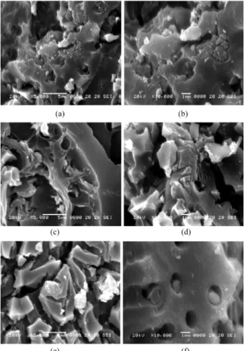
SEM images of Co-AC/TiO
2composites prepared with different concentration of CoCl
2are shown in Fig. 3.
According to the Fig. 3, we can observe that the AC has much pore structure. And the cobalt and TiO
2particles are jammed into the pore of AC or coated on the AC, which was consistent with the N
2adsorption experiment. In comparison of different concentrations of CoCl
2on AC surface, there was no significant difference.
EDX microanalyses of Co-AC/TiO
2composites prepared with different concentration of CoCl
2are shown in Table 3. It can be clearly seen that the composite contained four
Fig. 2. XRD patterns of Co-AC/TiO2 composites prepared by usingdifferent concentration of CoCl2; (a) CoAT1, (b) CoAT2 and (c) CoAT3.
Table 2. BET surface area of pristine AC and Co-AC/TiO2 composites
Samples SBET (m2/g)
Pristine AC 1083
CoAT1 682
CoAT2 670
CoAT3 389
Fig. 3. SEM images of Co-AC/TiO2 composites prepared by using different concentration of CoCl2; (a) and (b) CoAT1, (c) and (d) CoAT2, and (e) and (f) CoAT3.
kinds of main elements C, O, Ti and Co. And the amount of Co element increased with an increase of concentration of CoCl
2reacted. It could be considered that after heat treat- ment at 973 K, the composite was successfully prepared.
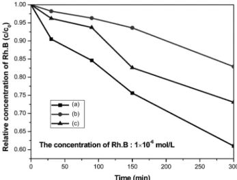
3.2 Degradation of dye solution
In this study, we choose the MO and Rh.B solution as organic dye solution for determining the degradation effect of Co-AC/TiO
2composites under irradiation of visible light. Fig. 4 and Fig. 5 show the relative concentration (c/
c
0) of MO and Rh.B in the aqueous solution on time under irradiation of visible light for Co-AC/TiO
2composites. As shown in the Fig. 4 and Fig. 5, the concentrations of MO and Rh.B solution decreased regularly with an increase of irradiation time for all of samples. After irradiation for 300 min, all of samples have good degradation efficiency of MO. And the degradation efficiency of MO increased with an increase concentration of CoCl
2which degraded 60, 65 and 70% of MO solution for samples CoAT1, CoAT2 and CoAT3, respectively. However, the degradation efficiency of Rh.B is relatively lower than that of MO.
After irradiation for 300 min, the Rh.B solution is degraded only 17% for sample CoAT2, and samples CoAT1 and CoAT3 degrade 59 and 27 % Rh.B solution. From our
previous work,
21)it can be considered that the particle size of Rh.B is larger than that of MO, thus the degradation efficiency of Rh.B is lower than that of MO.
The decomposition of MO and Rh.B by Co-AC/TiO
2composites under irradiation of visible light can be con- sidered as combined effects of adsorption effect by AC and photo degradation effect by TiO
2. The prepared samples must have good adsorption effect due to the large BET surface area. As we known, the TiO
2does not act with the visible light effectively. However, in our study, we used Co metal as transition metal, when Co ions incorporated into the lattice of TiO
2, the level appeared between the valence band (VB) and the conduction band (CB) of
Table 3. EDX elemental microanalysis (wt.%) of Co-AC/TiO2composites prepared by using different concentration of CoCl2
Samples Elements
C O Ti Co
CoAT1 20.22 23.67 53.64 2.47
CoAT2 44.39 17.79 35.10 2.73
CoAT3 42.45 14.54 35.08 7.94
Fig. 4. Dependence of relative concentration (c/c0) of MO in the aqueous solution on visible light irradiation time for the Co-AC/
TiO2 composites prepared from the different Co molar ratios; (a) CoAT1, (b) CoAT2 and (c) CoAT3.
Fig. 5. Dependence of relative concentration (c/c0) of Rh.B in the aqueous solution on visible light irradiation time for the Co-AC/
TiO2 composites prepared from the different Co molar ratios; (a) CoAT1, (b) CoAT2 and (c) CoAT3.
Fig. 6. The simple mechanism of dye degradation by Co-AC/TiO2
composites.
TiO
2,
22)thus altering the band-gap energy and shift the absorbance edge to the visible light region. The simple mechanism of MO and Rh.B degradation by Co-AC/TiO
2composites is shown in Fig. 6.
4. Conclusion
The AC modified by different concentration of cobalt chloride, and then reacted with TOS for the preparation of Co-AC/TiO
2composites by sol-gel method. N
2adsorption data showed that the composites had decreased surface area compared with the pristine AC. XRD results showed that Co-AC/TiO
2composites contained a mixing anatase and rutile phase. EDX results showed the presence of C, O, and Ti with Co element in the Co-AC/TiO
2composites.
Furthermore, the adsorption effect by AC and the photo- catalytic effect by TiO
2confirmed by the decomposition processes for the organic dyes (MO and Rh.B). And, the Co combined photocatalysts could enhance photo degrad- ation behaviors of the composites under visible light.
References
1. H. Lachheb, E. Puzenat, A. Houas, M. Ksibi, E. Elaloui, C. Guillard and J. M. Herrmann, Appl. Catal. B, 39, 75 (2002).
2. S. Fukahori, H. Ichiura, T. Kitaoka and H. Tanaka, Appl.
Catal. B, 46, 453 (2003).
3. G. Alhakimi, L. H. Studnicki and M. Al-Ghazali, J.
Photochem. Photobiol. A, 154, 219 (2003).
4. F. Shiraishi, S. Yamaguchi and Y. Ohbuchi, Chem. Eng.
Sci., 58, 929 (2003).
5. H. Chun, W. Yizhonga and T. Hongxiao, Chemosphere, 41, 1205 (2000).
6. Z. Ding, H. Y. Zhu, G. Q. Lu and P. F. Greenfield, J.
Colloid Interface Sci., 209, 193 (1999).
7. M. A. Barakat, H. Schaeffer, G. Hayes and S. Ismat- Shah, Appl. Catal. B: Environ., 57, 23 (2005).
8. R. Asahi, T. Morikawa, T. Ohwaki, K. Aoki and Y. Taga, Science, 293, 269 (2001).
9. J. -C. Xu, Y. -L. Shi, J. -E. Huang, B. Wang and H. -L.
Li, J. Mol. Catal. A: Chem., 219, 351 (2004).
10. C. C. Pan and J. C. S. Wu, Mater. Chem. Phys., 100, 102 (2006).
11. W. C. Oh and M. L. Chen, J. Ceram. Process. Res., 9, 100 (2008).
12. J. Arana and J. M. Dona, Appl. Catal. B: Environ., 44, 161 (2003).
13. S. X. Liu, X. Y. Chen and X. Chen, J. Hazard. Mater., 143, 257 (2007).
14. W. C. Oh, M. L. Chen and C. S. Lim, J. Ceram. Process.
Res., 8, 119 (2007).
15. W. C. Oh, J. S. Bae, M. L. Chen and Y. S. Ko, Analytical Science & Technology, 19, 376 (2006).
16. W. C. Oh, J. S. Bae and M. L. Chen, Bull. Kor. Chem.
Soc., 27, 1423 (2006).
17. L. P. Zhu, G. H. Liao, W. Y. Huang, L. L. Ma, Y. Yang, Y. Yu and S. Y. Fu, Mater. Sci. Eng. B, 163, 194 (2009).
18. X. K. Wang, J. G. Wang, P. Q. Guo, W. L. Guo and C.
Wang, J. Hazard. Mater., 169, 486 (2009).
19. M. Inagaki, Y. Hirose, T. Matsunage, T. Tsumura and M.
Toyoda, Carbon, 41, 2619 (2003).
20. M. L. Chen, J. S. Bae and W. C. Oh, Analytical Science
& Technology, 19, 460 (2006).
21. Y. G. Go, H. J. Kwon, M. L. Chen, F. J. Zhang and W.
C. Oh, Kor. J. Mater. Res., 19, 555 (2009).
22. Y. L. Dong, J. L. Won, S. Jae Sung, H. K. Jung and S.
K. Yang, Comput. Mater. Sci., 30, 383 (2004).